Format: PDF (Printable Document)
File Language: English
File Pages: 271
File Size: 2.18 MB (Speed Download Link)
Brand: John Deere
Model: Diesel Engine Model 6059T 6 Cylinder 5.9 Liter
Book No: TM 9-2815-256-24
Type of Document: Technical Manual
$ 40
CHAPTER 1 INTRODUCTION ……………………………………………………………………………………………. 1-1
Section I. General Information ………………………………………………………………………………………… 1-1
Section II. Equipment Description and Data……………………………………………………………………….. 1-1
Section III. Preparation for Use …………………………………………………………………………………………. 1-4
CHAPTER 2 OPERATION………………………………………………………………………………………………….. 2-1
Section I. PRINCIPLES OF OPERATION…………………………………………………………………………. 2-1
Section II. OPERATING INSTRUCTIONS …………………………………………………………………………. 2-1
CHAPTER 3 MAINTENANCE……………………………………………………………………………………………… 3-1
Section I. PREVENTIVE MAINTENANCE CHECKS AND SERVICES (PMCS)……………………….. 3-1
Section II. Troubleshooting ……………………………………………………………………………………………… 3-2
Section III. General Maintenance………………………………………………………………………………………. 3-15
Section IV. Cooling System Maintenance……………………………………………………………………………. 3-21
Section V. Electrical System Maintenance …………………………………………………………………………. 3-27
Section VI. Intake and Exhaust System Maintenance……………………………………………………………. 3-51
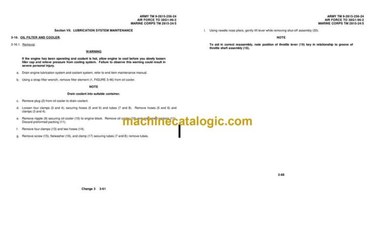
Section VII. Lubrication System Maintenance……………………………………………………………………….. 3-61
Section VIII. Fuel System Maintenance………………………………………………………………………………… 3-76
Section IX. Cylinder Head Assembly Maintenance ……………………………………………………………….. 3-139
Section X. Flywheel and Housing Assembly Maintenance …………………………………………………….. 3-159
Section XI. Crankshaft Pulley and Timing Gear Cover
Assembly Maintenance…………………………………………………………………………………. 3-164
Section XII. Camshaft Assembly Maintenance ……………………………………………………………………… 3-168
Section XIII. Idler Gears and Front Plate Assembly Maintenance ……………………………………………… 3-174
Section XIV. Crankshaft and Main Bearings Maintenance………………………………………………………… 3-180
Section XV. Pistons, Connecting Rods, Cylinder Liners,
and Engine Block Maintenance………………………………………………………………………. 3-190
APPENDIX A REFERENCES ………………………………………………………………………………………………. A-1
APPENDIX B MAINTENANCE ALLOCATION CHART……………………………………………………………… B-1
APPENDIX C EXPENDABLE/DURABLE SUPPLIES AND MATERIALS LIST………………………………. C-1
APPENDIX D FABRICATION OF TOOLS………………………………………………………………………………. D-1
APPENDIX E MAINTENANCE PROCEDURES AND AUTHORIZED LEVEL OF MAINTENANCE…… E-1
INDEX ……………………………………………………………………………………………………………………. Index-1
Change 1 ii
ARMY TM 9-2815-256-24
AIR FORCE TO 38G1-96-2
MARINE CORPS TM 2815-24/5
LIST OF ILLUSTRATIONS
FIGURE PAGE
1-1. Engine Components…………………………………………………………………………………………………………. 1-3
3-1. Connecting Test Gage to Intake Manifold…………………………………………………………………………….. 3-19
3-2. Thermostat and Housing …………………………………………………………………………………………………… 3-22
3-3. Engine Oil Cooler Hoses …………………………………………………………………………………………………… 3-24
3-4. Water Pump Assembly……………………………………………………………………………………………………… 3-25
3-5. Battery Charging Alternator and Mounting Brackets……………………………………………………………….. 3-28
3-6. Battery Charging Alternator Assembly …………………………………………………………………………………. 3-30
3-7. Stator and Rear Housing Separation …………………………………………………………………………………… 3-30
3-8. Testing Brush Assembly……………………………………………………………………………………………………. 3-31
3-9. Testing Diode-Trio……………………………………………………………………………………………………………. 3-31
3-10. Testing Rectifier Bridge …………………………………………………………………………………………………….. 3-32
3-11. Testing Stator Windings ……………………………………………………………………………………………………. 3-33
3-12. Testing Rotor…………………………………………………………………………………………………………………… 3-33
3-13. Battery Charging Alternator Test Circuit ………………………………………………………………………………. 3-34
3-14. Starter Bench Test Setup ………………………………………………………………………………………………….. 3-36
3-15. Starter Assembly……………………………………………………………………………………………………………… 3-37
3-16. Disconnecting Lead Wire (Typical) ……………………………………………………………………………………… 3-38
3-17. Removing Through Bolts (Typical) ……………………………………………………………………………………… 3-38
3-18. Removing Starter End Frame and Yoke Assembly (Typical)……………………………………………………. 3-39
3-19. Removing Brushes…………………………………………………………………………………………………………… 3-40
3-20. Removing Armature …………………………………………………………………………………………………………. 3-40
3-21. Removing Housing (Typical) ……………………………………………………………………………………………… 3-41
3-22. Removing Overrunning Clutch (Typical)………………………………………………………………………………. 3-41
3-23. Removing Steel Ball…………………………………………………………………………………………………………. 3-42
3-24. Removing Pinion, Retainer, and Rollers (Typical)………………………………………………………………….. 3-42
3-25. Removing Washer and Spring……………………………………………………………………………………………. 3-43
3-26. Checking Commutator Run-Out………………………………………………………………………………………….. 3-43
3-27. Measuring Commutator OD……………………………………………………………………………………………….. 3-44
3-28. Measuring Segment Mica Depth…………………………………………………………………………………………. 3-44
3-29. Inspecting and Replacing Bearings……………………………………………………………………………………… 3-45
3-30. Measuring Brush Length……………………………………………………………………………………………………. 3-45
3-31. Checking Overrunning Clutch…………………………………………………………………………………………….. 3-46
3-32. Starter Solenoid Test Circuit………………………………………………………………………………………………. 3-46
3-33. Growler Test……………………………………………………………………………………………………………………. 3-47
3-34. Testing for Grounded Windings………………………………………………………………………………………….. 3-47
3-35. Checking for Open Circuit Windings……………………………………………………………………………………. 3-47
3-36. Checking Brush Holder……………………………………………………………………………………………………… 3-48
3-37. Checking Field Coils…………………………………………………………………………………………………………. 3-48

