Format: PDF (Printable Document)
File Language: English
File Pages: 132
File Size: 13.49 MB (Speed Download Link)
Brand: Komatsu
Model: PC490LC-10
Book No: GEN00109-03
Serial No: 80001 and up
Type of Document: Shop Manual
$ 39
Precautions for field assembly ……………………………………………………………………………….. 2
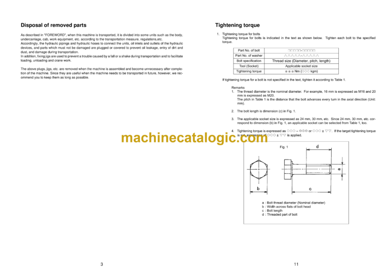
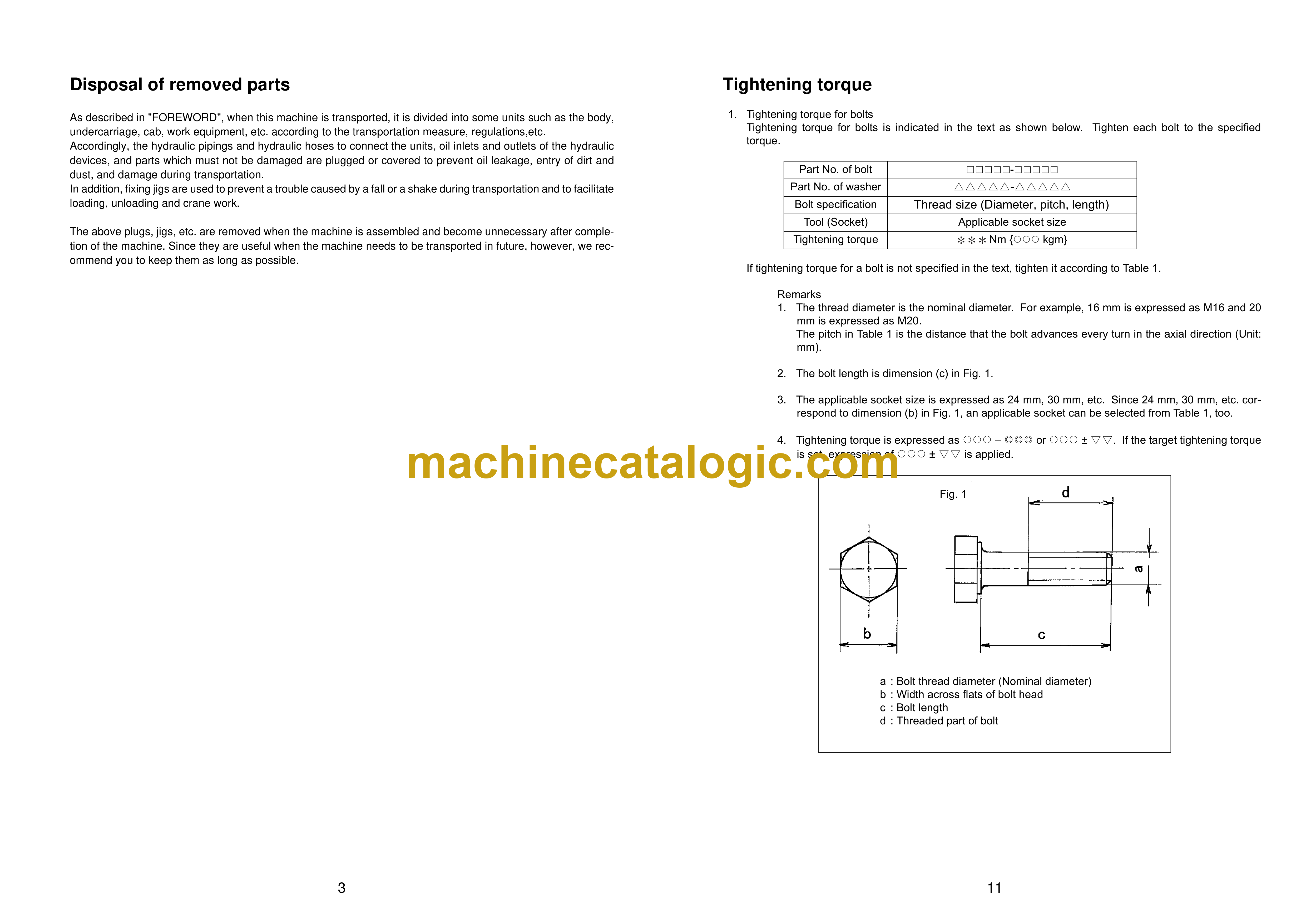
Disposal of removed parts……………………………………………………………………………………… 3
Assembling procedures, applicable equipment and schedule …………………………………….. 4
Flow of field assembly …………………………………………………………………………………………… 5
Kit layout diagram…………………………………………………………………………………………………. 6
Transportation ……………………………………………………………………………………………………… 7
Tool list for field assembly ……………………………………………………………………………………… 10
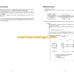
Tightening torque …………………………………………………………………………………………………. 11
Coating materials …………………………………………………………………………………………………. 16
Selection of wire ropes used for assembly……………………………………………………………….. 20
Selection of nylon slings used for assembly……………………………………………………………… 21
A. Assembly of chassis …………………………………………………………………………………………. 23
A- 1. Installation of climbing step ………………………………………………………………………… 24
A- 2. Installation of handrail ……………………………………………………………………………….. 25
A- 3. Installation of mirror…………………………………………………………………………………… 27
B. Assembling of work equipment …………………………………………………………………………… 31
B- 1. Installation of boom cylinder……………………………………………………………………….. 32
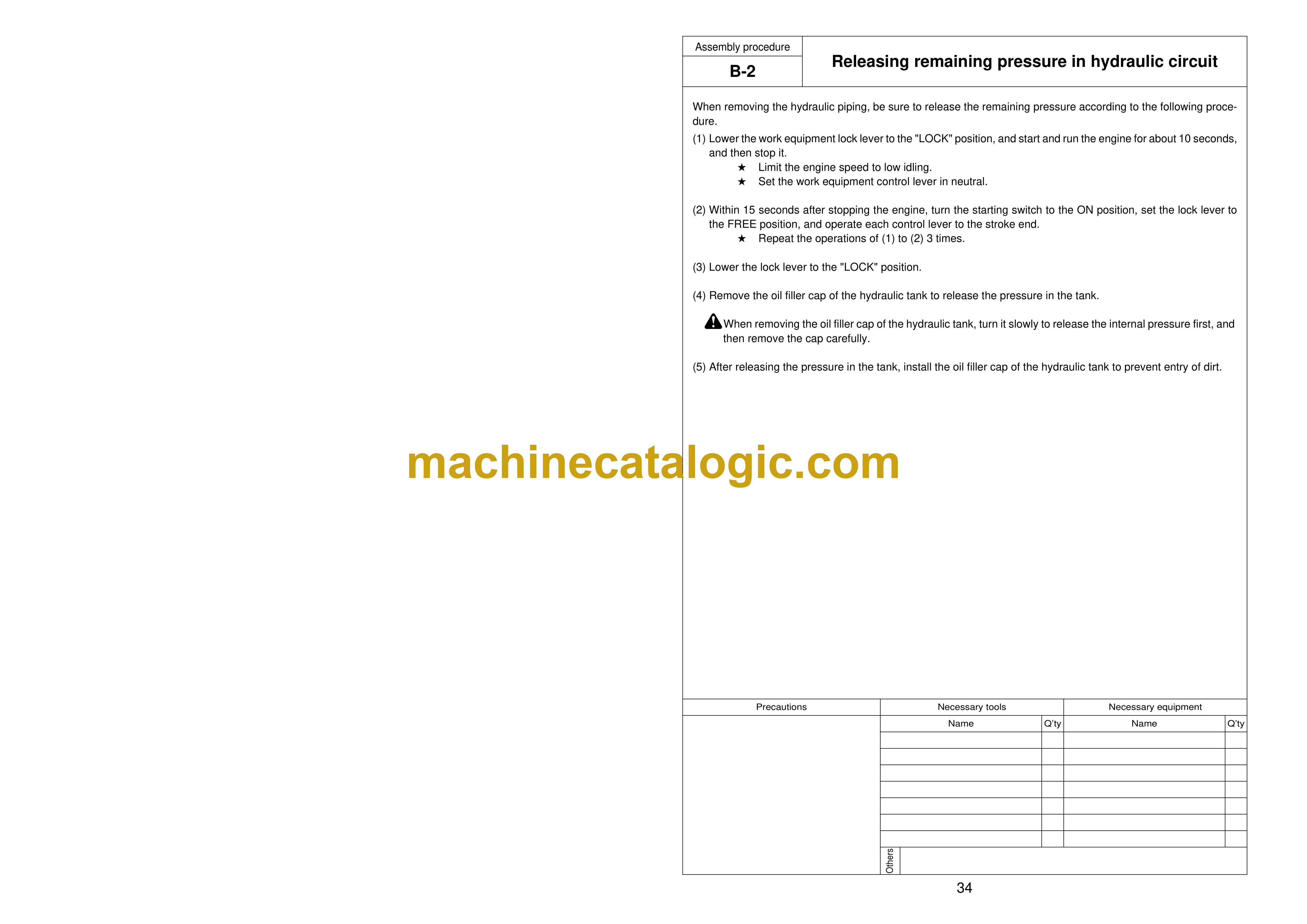
B- 2. Releasing remaining pressure in hydraulic circuit ………………………………………….. 34
B- 3. Installation of boom cylinder hoses ……………………………………………………………… 35
B- 4. Installation of boom cylinder top pin …………………………………………………………….. 36
B- 5. Installation of boom assembly…………………………………………………………………….. 37
B- 6. Installation of hoses from chassis along top of boom……………………………………… 40
B- 7. Connection of boom cylinder head………………………………………………………………. 41
B- 8. Installation of arm assembly……………………………………………………………………….. 42
B- 9. Installation of bucket cylinder hoses between boom and bucket cylinder ………….. 44
B-10. Installation of bucket…………………………………………………………………………………. 46
B-11. Connection of work equipment grease piping ………………………………………………. 49
B-12. Connection of work equipment wiring …………………………………………………………. 52
B-13. Greasing after completion of work equipment………………………………………………. 53
B-14. Bleeding air from work equipment circuit …………………………………………………….. 54
C. Increasing and decreasing of track frame gauge, assembling of counterweight………… 55
C- 1. Increasing and decreasing of track frame gauge…………………………………………… 56
C- 2. Installation of steps …………………………………………………………………………………… 62
C- 3. Installation of travel piping covers ………………………………………………………………. 63
C- 4. Adjustment of track tension ……………………………………………………………………….. 67
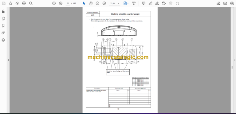
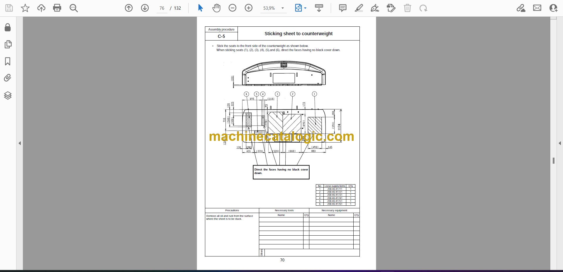
C- 5. Sticking sheet to counterweight ………………………………………………………………….. 70
C- 6. Installation of camera………………………………………………………………………………… 71
C- 7. Installation of counterweight……………………………………………………………………….. 77
M. Procedure for inspection and maintenance after completion of assembly ………………… 81
M- 1. Replacement of return filter (Standard filter to flushing filter) ………………………….. 82
M- 2. Flushing of hydraulic circuit ……………………………………………………………………….. 83
M- 3. Replacement of return filter (Standard filter to flushing filter) ………………………….. 85
M- 4. Check of oil/coolant level at each part …………………………………………………………. 87
M- 5. Inspection of oil level in hydraulic tank and refill……………………………………………. 89
M- 6. Parts to be touched up after field assembly………………………………………………….. 91
M- 7. Error code……………………………………………………………………………………………….. 92


