Format: PDF
Language: EN
Size: 6.17 MB
Pages: 152
Speed Download Link
$ 50 Original price was: $ 50.$ 40Current price is: $ 40.
CATERPILLAR CT610-CT630 SYSTEMS OPERATION contains high quality images, diagrams, instructions to help you to operate, maintenance, diagnostic, and repair your machine. This document is printable, without restrictions, contains searchable text and bookmarks for easy navigation.
1. SAFETY PRECAUTIONS………………………………………………………………………………..
2. DESCRIPTION……………………………………………………………………………………….. 1
2.1. SYSTEM OPERATIONAL DESCRIPTION…………………………………………………….. 3
Air Distribution (General)………………………………………………………………………. 3
Air Distribution (Air Conditioning)………………………………………………………………. 5
Air Distribution (Heat and Ventilation)………………………………………………………….. 6
Air Distribution (Defrost)……………………………………………………………………….. 6
A/C Refrigerant Flow…………………………………………………………………………… 7
2.2. COMPONENTS………………………………………………………………………………… 9
Thermostatic Expansion Valve (TXV)………………………………………………………….. 9
Freeze Probe………………………………………………………………………………….. 9
Low-Pressure Switch…………………………………………………………………………… 9
Linear Power Module…………………………………………………………………………. 10
Recirculation Filter……………………………………………………………………………. 10
HVAC Control Panel………………………………………………………………………….. 10
2.3. INTERNAL COMPONENTS………………………………………………………………….. 11
Filter-Drier…………………………………………………………………………………….. 11
Heater Core…………………………………………………………………………………… 11
Blower Assembly……………………………………………………………………………… 12
Evaporator Core………………………………………………………………………………. 12
HVAC Filter…………………………………………………………………………………… 12
2.4. UNDER-HOOD COMPONENTS……………………………………………………………… 12
Pressure Transducer…………………………………………………………………………. 12
Compressor and Clutch………………………………………………………………………. 12
Condenser……………………………………………………………………………………. 12
A/C Plumbing…………………………………………………………………………………. 13
2.5. HVAC ELECTRICAL SYSTEM OVERVIEW………………………………………………….. 13
General Operation Of The HVAC Electrical System…………………………………………… 13
3. SYSTEM OPERATION………………………………………………………………………………. 14
3.1. CONTROL ASSEMBLY………………………………………………………………………. 14
3.2. BLOWER FAN SPEED CONTROL…………………………………………………………… 14
3.3. TEMPERATURE CONTROL………………………………………………………………….. 14
3.4. MODE CONTROL……………………………………………………………………………. 14
MAX Air Conditioning Mode…………………………………………………………………… 15
NORM Air Conditioning Mode………………………………………………………………… 15
Bi-Level Air Conditioning Mode……………………………………………………………….. 16
Vent Mode……………………………………………………………………………………. 16
Floor Mode……………………………………………………………………………………. 16
Mix Mode……………………………………………………………………………………… 16
Defrost……………………………………………………………………………………….. 16
3.5. DEHUMIDIFYING…………………………………………………………………………….. 16
4. SERVICE PROCEDURES FOR R-134A…………………………………………………………….. 17
4.1. R-134A SERVICE PRECAUTIONS…………………………………………………………… 18
4.2. RECOMMENDED SERVICE TOOLS…………………………………………………………. 20
4.3. SEALANT DETECTION………………………………………………………………………. 20
4.4. REFRIGERANT IDENTIFICATION…………………………………………………………… 21
4.5. LEAK DETECTION…………………………………………………………………………… 22
Leak Detection……………………………………………………………………………….. 22
Refrigerant Leak Detector (D400A-NAV)……………………………………………………… 23
Ultrasonic Leak Detector……………………………………………………………………… 23
Refrigerant Leak Testing with Nitrogen……………………………………………………….. 24
4.6. AUTOMATIC MODE………………………………………………………………………….. 26
4.7. DISCHARGING THE A/C SYSTEM (RECYCLE MODE)……………………………………… 28
4.8. EVACUATING THE A/C SYSTEM (VACUUM MODE)………………………………………… 30
4.9. CHARGING THE A/C SYSTEM (CHARGE MODE)………………………………………….. 31
4.10. FLUSHING AND PURGING THE A/C SYSTEM……………………………………………… 33
Flushing Using the A/C Servicing System (Recommended Method)………………………….. 34
Alternate Method for Flushing (and Purging) the A/C System………………………………… 36
4.11. OIL FILL GUIDELINES……………………………………………………………………….. 37
Oil Separation During Refrigerant Recovery………………………………………………….. 38
Excessive Oil Loss Due to Refrigerant Leaks…………………………………………………. 38
4.12. CHECKING COMPRESSOR OIL LEVEL…………………………………………………….. 41
5. REMOVAL AND INSTALLATION …………………………………………………………………… 44
5.1. PRESSURE TRANSDUCER…………………………………………………………………. 46
Pressure Transducer – Removal……………………………………………………………… 46
Pressure Transducer – Installation……………………………………………………………. 46
5.2. LOW-PRESSURE SWITCH………………………………………………………………….. 47
Low-Pressure Switch – Removal……………………………………………………………… 47
Low-Pressure Switch – Installation……………………………………………………………. 48
5.3. FREEZE PROBE……………………………………………………………………………… 49
Freeze Probe – Removal……………………………………………………………………… 49
Freeze Probe – Installation…………………………………………………………………… 50
5.4. HVAC AIR FILTER……………………………………………………………………………. 51
HVAC Air Filter – Removal……………………………………………………………………. 51
HVAC Air Filter – Installation………………………………………………………………….. 51
5.5. REFRIGERANT LINES……………………………………………………………………….. 52
Refrigerant Line – Removal…………………………………………………………………… 52
Refrigerant Line – Installation…………………………………………………………………. 53
5.6. FILTER-DRIER……………………………………………………………………………….. 54
Filter-Drier – Removal………………………………………………………………………… 54
Filter-Drier – Installation………………………………………………………………………. 55
5.7. THERMOSTATIC EXPANSION VALVE (TXV)………………………………………………… 56
Thermostatic Expansion Valve (TXV) – Removal…………………………………………….. 56
Thermostatic Expansion Valve (TXV) – Installation…………………………………………… 57
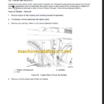
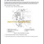
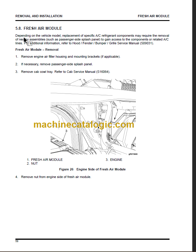
5.8. FRESH AIR MODULE………………………………………………………………………… 58
Fresh Air Module – Removal…………………………………………………………………. 58
Fresh Air Module – Installation……………………………………………………………….. 59
5.9. INTERIOR MODULE TRIM COVER………………………………………………………….. 60
Interior Module Trim Cover – Removal……………………………………………………….. 60
Interior Module Trim Cover – Installation……………………………………………………… 61
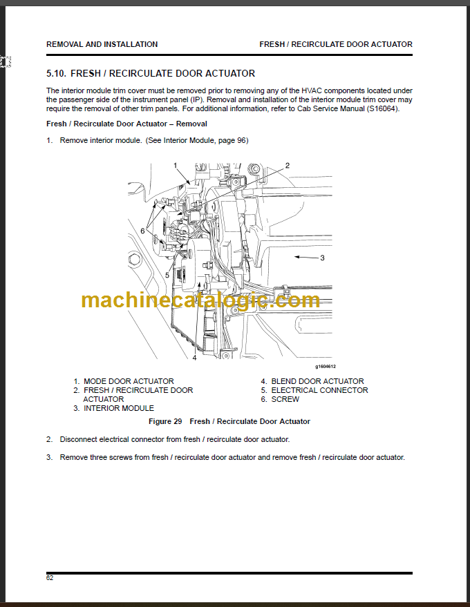
5.10. FRESH / RECIRCULATE DOOR ACTUATOR………………………………………………… 62
Fresh / Recirculate Door Actuator – Removal………………………………………………… 62
Fresh / Recirculate Door Actuator – Installation………………………………………………. 63
5.11. BLEND DOOR ACTUATOR………………………………………………………………….. 64
Blend Door Actuator – Removal………………………………………………………………. 64
Blend Door Actuator – Installation…………………………………………………………….. 65
5.12. MODE DOOR ACTUATOR…………………………………………………………………… 66
5.13. FRESH / RECIRCULATE DOOR GEAR TRAIN………………………………………………. 68
Fresh / Recirculate Door Gear Train – Removal………………………………………………. 68
Fresh / Recirculate Door Gear Train – Installation……………………………………………. 69
5.14. BLEND DOOR GEAR TRAIN…………………………………………………………………. 71
Blend Door Gear Train – Removal……………………………………………………………. 71
Blend Door Gear Train – Installation………………………………………………………….. 73
5.15. MODE DOOR GEAR TRAIN…………………………………………………………………. 75
Mode Door Gear Train – Removal……………………………………………………………. 75
Mode Door Gear Train – Installation………………………………………………………….. 77
5.16. RECIRCULATION FILTERS………………………………………………………………….. 79
Recirculation Filters – Removal………………………………………………………………. 79
Recirculation Filters – Installation…………………………………………………………….. 80
5.17. LINEAR POWER MODULE (LPM)……………………………………………………………. 81
Linear Power Module (LPM) – Removal………………………………………………………. 81
Linear Power Module (LPM) – Installation……………………………………………………. 82
5.18. BLOWER ASSEMBLY………………………………………………………………………… 83
Blower Assembly – Removal…………………………………………………………………. 83
Blower Assembly – Installation……………………………………………………………….. 83
5.19. HEATER CORE………………………………………………………………………………. 84
Heater Core – Removal………………………………………………………………………. 84
Heater Core – Installation…………………………………………………………………….. 85
5.20. HVAC CONTROL PANEL ASSEMBLY……………………………………………………….. 86
HVAC Control Panel Assembly – Removal……………………………………………………. 86
HVAC Control Panel Assembly – Installation…………………………………………………. 86
5.21. COMPRESSOR / CLUTCH…………………………………………………………………… 87
Compressor / Clutch – Removal………………………………………………………………. 87
Compressor / Clutch – Installation……………………………………………………………. 88
5.22. A/C CONDENSER……………………………………………………………………………. 89
5.23. HEATER HOSES / LINES…………………………………………………………………….. 89
5.24. EVAPORATOR……………………………………………………………………………….. 90
Evaporator – Removal………………………………………………………………………… 90
Evaporator – Installation……………………………………………………………………… 91
5.25. BLOWER SCROLL HOUSING……………………………………………………………….. 92
Blower Scroll Housing – Removal…………………………………………………………….. 92
Blower Scroll Housing – Installation…………………………………………………………… 93
5.26. SPLITTING / SEPARATING BLOWER SCROLL HOUSING………………………………….. 94
Splitting / Separating Blower Scroll Housing – Removal………………………………………. 94
Splitting / Separating Blower Scroll Housing – Installation……………………………………. 95
5.27. INTERIOR MODULE…………………………………………………………………………. 96
Interior Module – Removal……………………………………………………………………. 96
Interior Module – Installation………………………………………………………………… 101
5.28. SPLITTING / SEPARATING INTERIOR MODULE…………………………………………… 103
Splitting / Separating Interior Module – Removal……………………………………………. 103
Splitting / Separating Interior Module – Installation………………………………………….. 106
5.29. FRESH / RECIRCULATE, MODE, AND BLEND AIR DOORS………………………………. 107
6. DIAGNOSIS AND TROUBLESHOOTING………………………………………………………….. 108
6.1. PRELIMINARY CHECKS……………………………………………………………………. 108
Check for Obvious Damage…………………………………………………………………. 108
Refrigerant Identification…………………………………………………………………….. 108 and more