Format: PDF (Printable Document)
File Language: English
File Pages: 306
File Size: 51.03 MB (Speed Download Link)
Brand: Doosan (Daewoo)
Model: D35S-2, D40S-2, D45S-2, D40SC-2, D45SC-2, D50SC-2 G35S-2, G40S-2, G45S-2, G40SC-2, G45SC-2, G50SC-2
Type of Document: Service Manual
$ 40
Index
Chapter 1. GENERAL INFORMATION
Precautions before Service…………………………… 7
Tightening Torque ……………………………………… 10
Recommended Lubricants and Capacities……. 11
Engine Model and Engine Serial Number ……… 12
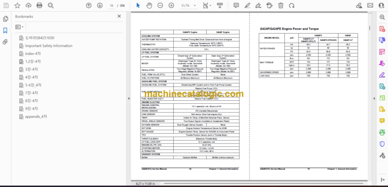
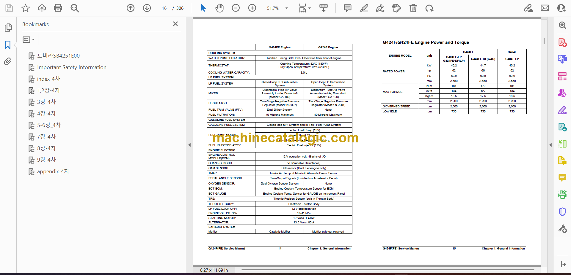
General Specification …………………………………. 13
G424F/G424FE Engine Power and Torque…….. 15
Chapter 2. RECOMMENDED
MAINTENANCE
General Maintenance………………………………….. 16
Test Fuel System for Leaks……………………… 16
Inspect Engine for Fluid Leaks …………………. 16
Inspect Vacuum Lines and Fittings……………. 16
Inspect Electrical System………………………… 16
Inspect Foot Pedal Operation…………………… 16
Engine Oil Classification………………………….. 17
Checking Engine Oil Level ………………………. 18
Replacing Engine Oil and Filter ………………… 18
Checking Compressed Pressure………………. 19
Cooling System Maintenance………………………. 20
Coolant Recommendation……………………….. 20
Check Coolant Level ………………………………. 20
Inspect Coolant Hoses……………………………. 20
Checking coolant leaks …………………………… 21
Specific gravity test ………………………………… 21
Relation between Coolant concentration and
Specific Gravity……………………………………… 21
Checking and Adjusting Drive Belt ……………. 22
Adjusting………………………………………………. 22
Checking Belt for Damage ………………………. 22
Ignition System Maintenance………………………. 23
Inspect Battery System…………………………… 23
Inspect Ignition System…………………………… 23
Inspection of Ignition Timing ……………………. 23
Inspection of Spark Plug…………………………. 24
Fuel System Maintenance…………………………… 26
Replace LP Fuel Filter Element………………… 26
Testing Fuel Lock-off Operation……………….. 26
Pressure Regulator/Converter Inspection…… 27
Inspect Air/Fuel Valve Mixer Assembly ……… 27
Inspect for Intake Leaks………………………….. 27
Inspect Throttle Assembly……………………….. 27
Checking the TMAP Sensor…………………….. 27
Exhaust System Maintenance……………………… 27
Inspect Engine for Exhaust Leaks…………….. 27
Maintenance Schedule ……………………………….. 28
Chapter 3. ENGINE MECHANICAL
SYSTEM
General Information……………………………………. 30
Engine Outline………………………………………. 30
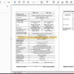
Technical Specifications …………………………. 31
Shells Selection Table ……………………………. 33
Recommended Torque Values…………………. 36
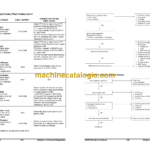
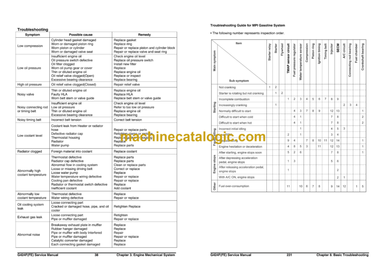
Troubleshooting…………………………………….. 38
Engine Exploded View………………………………… 39
Intake manifold and gasket…………………………. 41
Exhaust Manifold and Gasket ……………………… 45
Timing Belt………………………………………………… 47
Timing Belt Tensioner ………………………………… 51
PCV Valve …………………………………………………. 52
Camshaft Timing Pulley and/or Seal…………….. 55
Crankshaft Timing Pulley……………………………. 55
Crankshaft Front Seal ………………………………… 56
Camshaft Case Cover and Gasket……………….. 56
Crankshaft Accessory Pulley………………………. 57
Timing Belt Rear Cover ………………………………. 57
Rocker Arms, Linkage, Valve Lifters With
Cylinder Head and Eegine…………………………. 59
Cooling System………………………………………….. 60
Thermostat Housing…………………………………… 66
Water Pump……………………………………………….. 67
Lubrication System…………………………………….. 68
Oil Pan………………………………………………………. 71
Oil Pump……………………………………………………. 72
Oil Pump Assembly ……………………………………. 73
Camshaft Case Assembly …………………………… 74
Cylinder Head…………………………………………….. 78
Valve, Spring or Seal ………………………………….. 79
Engine Disassembly…………………………………… 81
Engine Assembly……………………………………….. 85
Cylinder Block……………………………………………. 90
Crankshaft…………………………………………………. 91
Pistons and/or Connecting Rods…………………. 97
Rings …………………………………………………….. 9999
Chapter 4. ENGINE ELECTRICAL
SYSTEM
Specifications ………………………………………….. 101
Ignition System………………………………………… 102
Wasted Spark DIS Ignition System………….. 102
Inspection of Ignition Coil ………………………. 103
Spark Plug Wire Inspection……………………. 104
Spark Plug Wire Replacement ……………….. 104
Spark Plug Replacement……………………….. 105
Spark Plug Inspection …………………………… 105
Charging System……………………………………… 107
General Description ……………………………… 107
Troubleshooting Procedure ……………………. 110
STARTING SYSTEM………………………………….. 115
General Description ……………………………… 115
Diagnosis Procedure ……………………………..116
Start Relay Tests…………………………………..118
Troubleshooting…………………………………….119
Chapter 5. ENGINE MANAGEMENT
SYSTEM (EMS)
General Information……………………………………121
Specifications ……………………………………….121
Service Standard…………………………………..126
Component Location………………………………127
G424FE EMS (Engine Management System)
Overview…………………………………………………..131
General Description……………………………….131
LPG Fuel System Operation ……………………134
MPI Gasoline System Operation………………141
Electronic Throttle System………………………142
Ignition System……………………………………..143
Exhaust System…………………………………….144
SECM………………………………………………….146
SECM Wiring Diagrams for G424FE…………149
G424F EMS (Engine Management System)
Overview…………………………………………………..152
General Description……………………………….152
LPG Fuel System Operation ……………………155
Electronic Throttle System………………………159
Ignition System……………………………………..159
SECM………………………………………………….159
SECM Wiring Diagrams for G424F LP Engine
…………………………………………………………..160
G424F(FE) Service Manual 5 Index
EMS Inspection and Repair ……………………….. 161
Engine Control Module (SECM) ……………… 161
Camshaft Position Sensor……………………… 163
IAT (Intake Air Temperature) Sensor……….. 167
Oxygen Sensor (Pre-Catalyst)………………… 168
Oxygen Sensor (Post-Catalyst) ………………. 169
ECT (Engine Coolant Temperature) Sensor 170
LP Fuel Temperature Sensor …………………. 172
Angle Sensor-Accelerator ……………………… 173
Transmission Oil Temperature Switch……… 174
Ground Speed Limit Switch (optional) ……… 175
Electronic Throttle Body ………………………… 176
Chapter 6. LPG FUEL DELIVERY
SYSTEM
G424FE LP System Inspection and Repair ….. 177
Removal and Installation……………………….. 177
Hose Connections………………………….. 178
Removal and Installation of N-2007 LP
Regulator ……………………………………… 180
Removal and Installation of CA100 Mixer
for G424FE…………………………………… 181
Tests and Adjustments………………………….. 183
N-2007 Regulator Service Testing…….. 183
AVV (Air Valve Vacuum) Testing………. 185
Connection of the MI-07 Service Tool… 185
Idle Mixture Adjustment…………………… 186
Parts Description………………………………….. 189
CA100 Mixer for G424FE Engine ……… 189
N-2007 Regulator for G424FE Engine.. 191
G424F LPG System Inspection and Repair….. 193
Removal and Installation……………………….. 193
G424F Fuel System Connections……… 194
Removal and Installation of N-2001 LP
Regulator/Converter……………………….. 195
Removal and Installation of CA100 Mixer
for G424F …………………………………….. 196
Tests and Adjustments………………………….. 198
N-2001 Regulator Service Testing ……..198
AVV (Air Valve Vacuum) Testing ……….200
Connection of the MI-07 Service Tool …200
Idle Mixture Adjustment ……………………201
Parts Description …………………………………..203
CA100 Mixer for G424F Engine …………203
CA100 Disassembly and Service……….205
CA100 Disassembled Service……………206
N-2001 Regulator for G424F Engine…..207
N2001 Regulator Disassembly Steps: …209
N2001 Disassembled Service ……………211
Chapter 7. MPI GASOLINE FUEL
DELIVERY SYSTEM
Specification……………………………………………..212
Components Location………………………………..213
Fuel Pressure Test …………………………………….214
Injector……………………………………………………..216
Fuel Pump…………………………………………………219
Chapter 8. BASIC TROUBLESHOOTING
Preliminary Checks ……………………………………220
Before Starting ……………………………………..220
Visual/Physical check …………………………….220
Basic Troubleshooting Guide ……………………..221
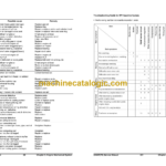
Customer Problem Analysis Sheet……………221
Basic Inspection Procedure …………………….222
Connector Inspection Procedure………………223
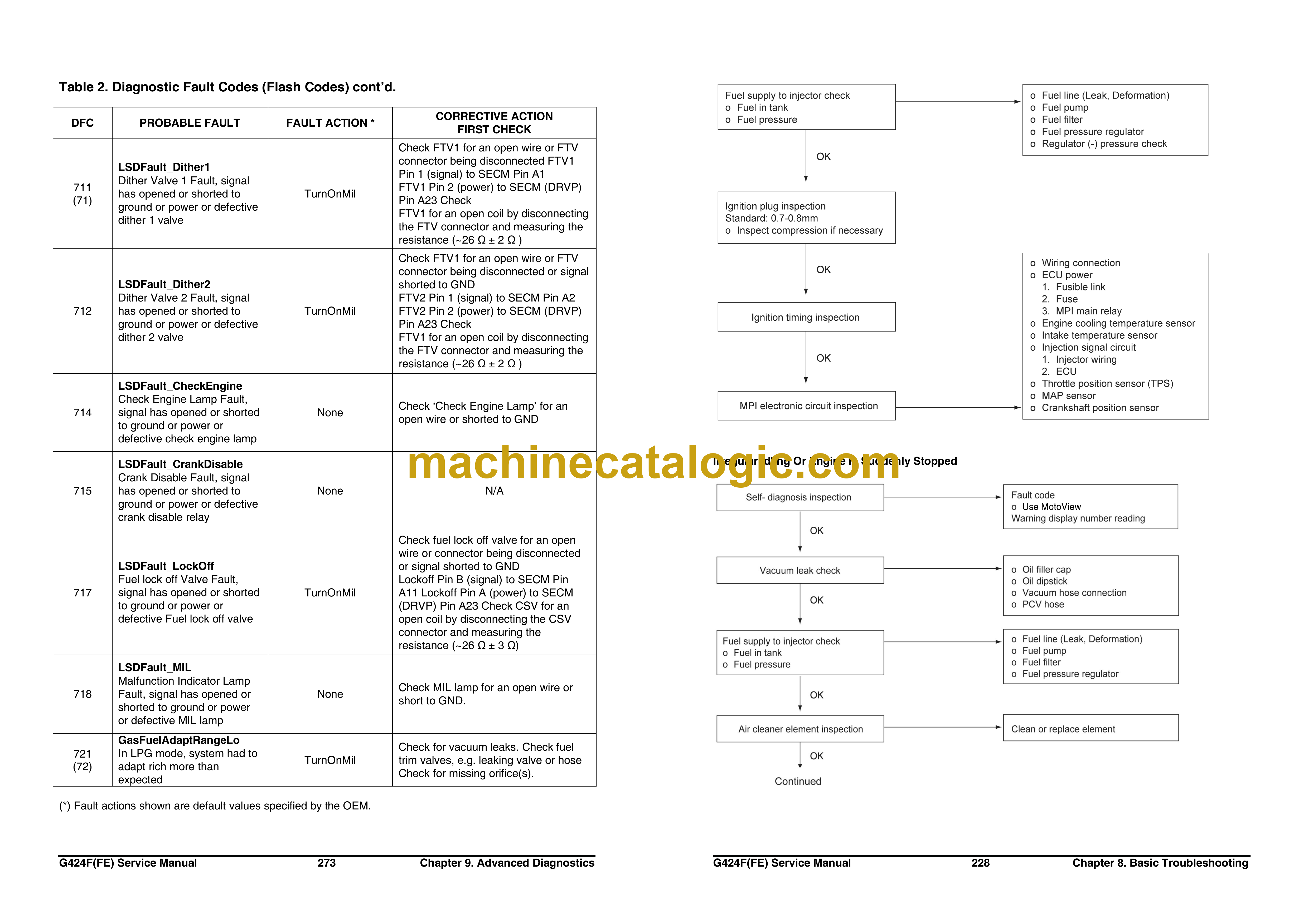
Symptom Troubleshooting Guide Chart …….227
Basic Troubleshooting……………………………….233
Intermittents………………………………………….233
Surges and/or Stumbles …………………………234
Engine Cranking but Will Not Start / Difficult to
Start ……………………………………………………235
Lack of Power, Slow to Respond / Poor High
Speed Performance / Hesitation During
Acceleration………………………………………… 237
Detonation / Spark Knock………………………. 239
Backfire ……………………………………………… 240
Dieseling, Run-on ………………………………… 240
Rough, Unstable, Incorrect Idle, or Stalling.. 241
Cuts Out, Misses………………………………….. 243
Poor Fuel Economy / Excessive Fuel
Consumption LPG Exhaust Smell …………… 244
High Idle Speed …………………………………… 245
Excessive Exhaust Emissions or Odors……. 246
Diagnostic Aids for Rich / Lean Operation … 247
Chart T-1 Restricted Exhaust System Check248
Chapter 9. ADVANCED DIAGNOSTICS
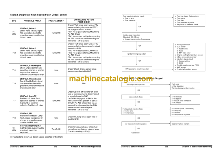
Reading Diagnostic Fault Codes………………… 249
Displaying Fault Codes (DFC) from SECM
Memory……………………………………………………. 249
Clearing Fault (DFC) Codes……………………….. 249
Fault Action Descriptions………………………….. 250
Fault List Definitions…………………………………. 250
Table 1. Fault List Definitions …………………. 251
Table 2. Diagnostic Fault Codes (Flash Codes)
…………………………………………………………. 261
Appendix
Service Tool Software (MotoView)……………….279
Introduction ………………………………………….279
Connection of the Service Tool ………………..280
MotoView Display Screens ……………………..281
SECM field update with Service Tool ………..293
Ground Speed Limits (Option)…………………….297
LPG And LPG Fuel Tanks …………………………..299
Regulatory Compliance………………………………303
Special Conditions for Safe Use………………….303
Abbreviations ……………………………………………304