Format: PDF
Language: EN
Size: 10.22 MB
Pages: 312
Speed Download Link
$ 50 Original price was: $ 50.$ 40Current price is: $ 40.
DC150 SERVICE MANUAL contains high quality images, diagrams, instructions to help you to operate, maintenance, diagnostic, and repair your machine. This document is printable, without restrictions, contains searchable text and bookmarks for easy navigation.
GENERALITIES
SAFETY RULES ……………………………………………………………………………………….. I – VIII
TABLE OF TECHNICAL DATA ……………………………………………………………………… 1 – 12
GENERAL INSTRUCTIONS…………………………………………………………………………. 14 – 18
TROUBLESHOOTING………………………………………………………………………………… 19
UNITS OF MEASURE ……………………………………………………………………………….. 20
CLASSIFICATION OF STANDARD COMPONENTS ………………………………………… 20 – 21
TABLE OF TIGHTENING TORQUES…………………………………………………………….. 22
ENGINE
GENERAL SPECIFICATIONS OF SERIES B ENGINE …………………………………… 1
Engine main specifications …………………………………………………………………………. 1
Engine identification …………………………………………………………………………………… 2
DESIGN FEATURES …………………………………………………………………………………. 3
SERVICEABILITY …………………………………………………………………………………….. 8
MOUNTING OF ENGINE ON FRAME ………………………………………………………….. 9
TRANSMISSION
2.1 GENERAL DESCRIPTION ……………………………………………………………………………. 2
2.1.1 Transmission converter hydraulic diagram ……………………………………………………….. 2
Transmission housing/propeller shaft/torque converter ………………………………………… 4
2.2 TROUBLESHOOTING ………………………………………………………………………………….. 5
2.3 TESTS ………………………………………………………………………………………………………. 9
2.3.1 Torque converter stall test …………………………………………………………………………….. 9
2.3.2 Delivery pressure test procedure ……………………………………………………………………. 9
2.3.3 Transmission gearshifting electric control valve ………………………………………………… 10
2.4 PROCEDURES FOR THE REPAIR OF THE TORQUE CONVERTER …………………… 12
2.4.1 Removal …………………………………………………………………………………………………….. 12
2.4.2 Re Installation ……………………………………………………………………………………………… 13
2.4.3 Disassembly ……………………………………………………………………………………………….. 14
2.4.4 Reassembly………………………………………………………………………………………………… 23
2.5 PROCEDURES FOR THE REPAIR OF THE TRANSMISSION ……………………………. 24
2.5.1 Removal …………………………………………………………………………………………………….. 24
2.5.2 Re Installation ……………………………………………………………………………………………… 25
2.5.3 Disassembly ……………………………………………………………………………………………….. 26
2.5.4 Overhaul of forward the speed clutch ………………………………………………………………. 40
2.5.5 Overhaul of Third speed …………………………………………………………………………………. 42
2.5.6 Overhaul of reverse speed clutch …………………………………………………………………… 47
2.5.7 Modulating valves (Disassembly/Assembly) …………………………………………………….. 51
2.5.8 Pressure relief valve (Disassembly/Assembly) …………………………………………………. 52
2.6 SPECIFICATIONS AND DATA………………………………………………………………………… 55
2.6.1 General data ……………………………………………………………………………………………….. 55
2.6.2 Tightening torques (Torque converter) ………………………………………………………….. 56
2.6.3 Transmission Data (Transmission housing) ……………………………………………………. 57
(Transmission clutches) …………………………………………………… 58
(Transmission clutch discs) ……………………………………………… 60
(First – Second – Third speed transmission clutch modulating
valves) …………………………………………………………………………. 60
(Lube oil pressure relief valve) …………………………………………… 61
(Forward/reverse modulating valves) …………………………………. 62
(Transmission pressure relief and torque converter safety valve) . 63
(Torque converter – transmission feeding pump) ………………….. 64
(Oil filters) …………………………………………………………………….. 65
FINAL DRIVES
3.1 GENERAL DESCRIPTION ……………………………………………………………………………. 1
3.1.1 Final drive (Exploded view and sectional view) …………………………………………………. 2
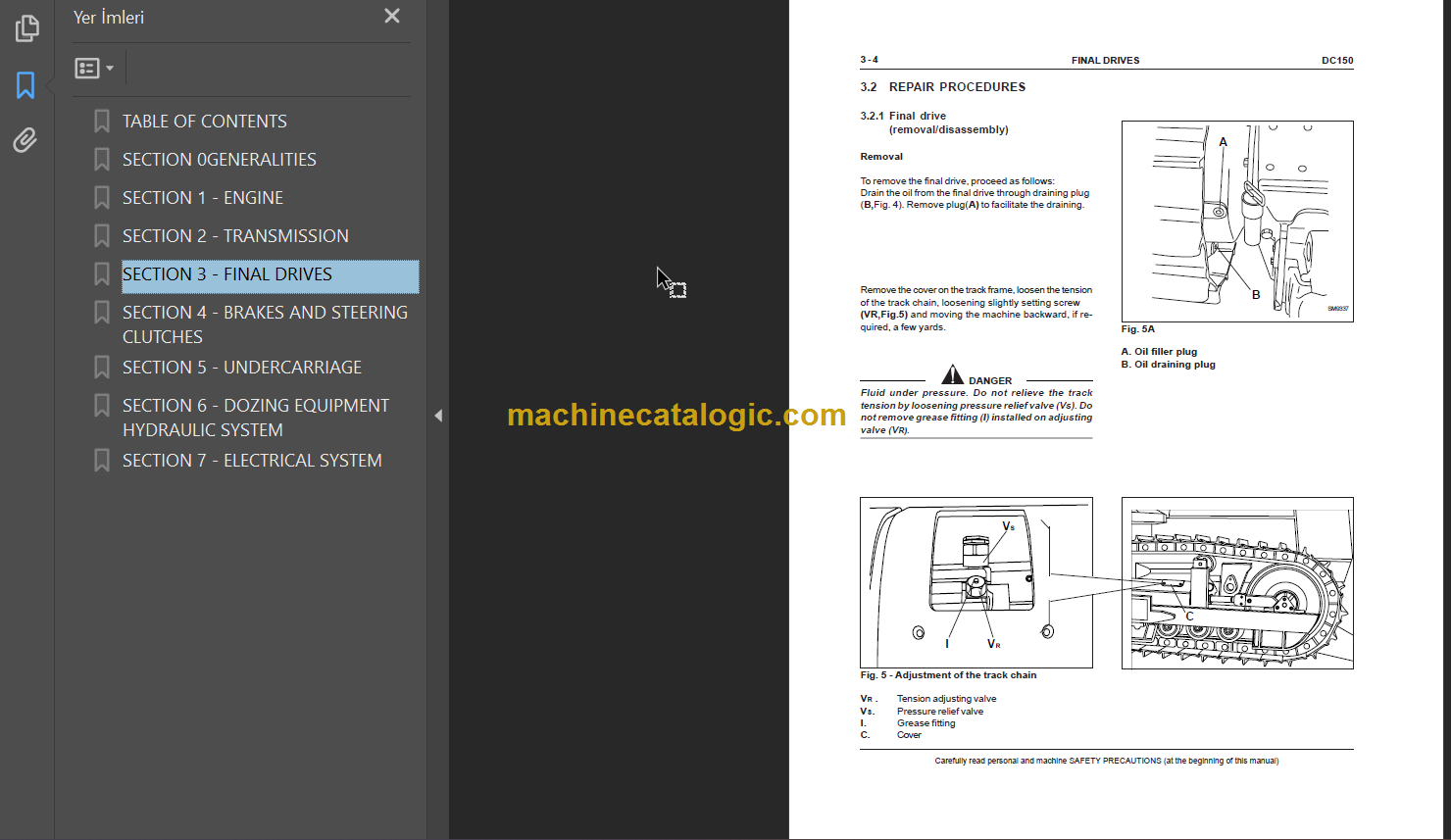
3.2 REPAIR PROCEDURES ……………………………………………………………………………….. 4
3.2.1 Final drive (removal/disassembly) ……………………………………………………………………. 4
3.2.2 Pulling the housing cover ………………………………………………………………………………. 8
3.2.3 Driven gear (bearing removal) ………………………………………………………………………… 9
3.2.4 Driving gear shaft (bearing removal) ………………………………………………………………… 9
3.2.5 Description of installation of front seals (long life) ……………………………………………… 10
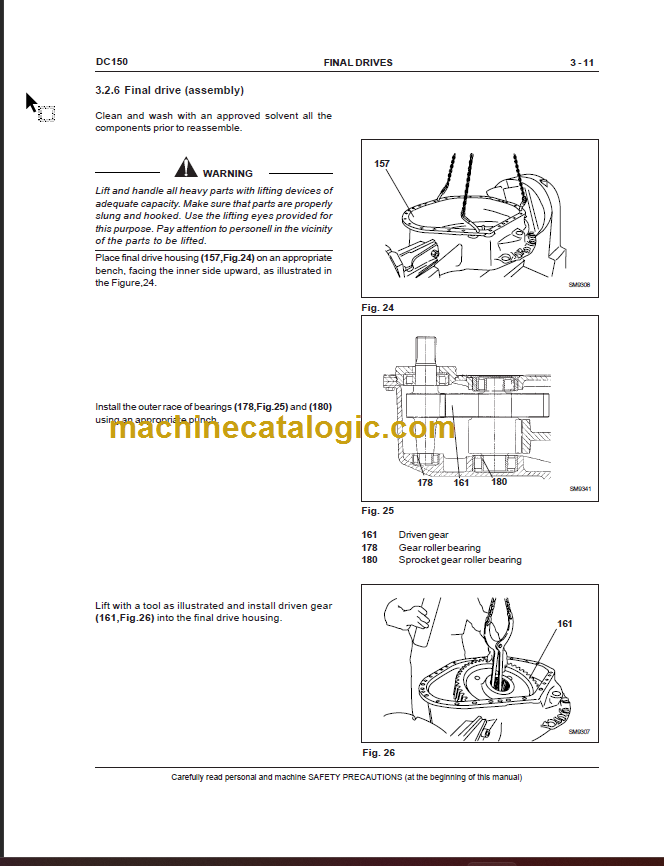
3.2.6 Final drive (assembly) …………………………………………………………………………………… 11
3.3 SPECIFICATIONS AND DATA………………………………………………………………………… 20
3.3.1 Final drive shaft and bearing fittings ……………………………………………………………….. 20
STEERING CLUTCHES – BRAKES
4.1 GENERAL DESCRIPTION OF THE CIRCUIT …………………………………………………… 2
4.1.1 Brakes and steering clutches system hydraulic diagram …………………………………….. 3
4.1.2 Main components of the hydraulic system ……………………………………………………….. 4
Brakes and steering clutches feeding pump ……………………………………………………… 4
Feeding valve block ……………………………………………………………………………………… 5
Proportional solenoid valves block ………………………………………………………………….. 6
Brake and clucthes Control valve …………………………………………………………………… 7
Brake pedal valve ………………………………………………………………………………………… 9
Oil filters …………………………………………………………………………………………………….. 11
Rear transmission (Gearbox side section) ………………………………………………………… 12
4.2 Troubleshooting ……………………………………………………………………………………………. 14
4.2.1 Diagnosis on the display ……………………………………………………………………………….. 15
4.3 TESTS ………………………………………………………………………………………………………. 17
4.3.1 Pressure test of the brakes and steering clutches circuit ……………………………………. 17
4.3.2 Brake pedal adjustment ………………………………………………………………………………… 19
4.3.3 Brake system pressure test …………………………………………………………………………… 20
4.3.4 Feeding valve test and setting ……………………………………………………………………….. 21
4.3.5 Brake levers/steering levers calibration ……………………………………………………………. 22
4.4 REPAIR PROCEDURES ……………………………………………………………………………….. 25
4.4.1 Brake pedal valve (removal/disassembly) …………………………………………………………. 25
4.4.2 Steering clutches and brake control feeding pump …………………………………………….. 26
4.4.3 Brakes and steering clutches …………………………………………………………………………. 27
4.4.4 Bevel gear unit (removal/disassembly) …………………………………………………………….. 32
4.4.4.1 Bevel ring gear removal ………………………………………………………………………………… 33
4.4.4.2 Bevel pinion removal ……………………………………………………………………………………. 37
4.4.4.3 Bevel gear crown disassembly ………………………………………………………………………. 38
4.4.4.4 Crown gear assembly …………………………………………………………………………………… 39
4.4.4.5 Bevel gear disassembly ………………………………………………………………………………… 39
4.4.4.6 Installation of bevel pinion …………………………………………………………………………….. 42
4.4.4.7 Re-installing the bevel gear crown …………………………………………………………………… 47
4.4.4.8 Re-installation of the bevel pinion …………………………………………………………………… 49
4.4.4.9 Setting the pinion-gear crown backlash ……………………………………………………………. 50
4.4.5 Steering/brakes control pilot valve ………………………………………………………………….. 51
4.4.5.1 Removal …………………………………………………………………………………………………….. 51
4.5 SPECIFICATIONS AND DATA………………………………………………………………………… 52
4.5.1 Bevel gear dimensions …………………………………………………………………………………. 52
4.5.2 Bevel gear reduction …………………………………………………………………………………….. 54
4.5.3 Steering clutches …………………………………………………………………………………………. 57
4.5.4 Brake pedal valve ………………………………………………………………………………………… 58
UNDERCARRIAGE
5.1 GENERAL DESCRIPTION ……………………………………………………………………………. 1
5.1.1 Generalities ………………………………………………………………………………………………… 1
5.1.2 Main components ………………………………………………………………………………………… 2
5.2 TROUBLESHOOTING ………………………………………………………………………………….. 5
5.3 INSPECTIONS ……………………………………………………………………………………………. 6
5.3.1 Inspection and adjustment of track chains ……………………………………………………….. 6
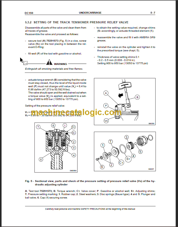
5.3.2 Setting of the track tensioner pressure relief valve …………………………………………….. 7
5.4 REPAIR PROCEDURES ……………………………………………………………………………….. 8
5.4.1 Track chain (removal/installation) ……………………………………………………………………. 8
5.4.2 Replacing a damaged link and reinstallation ……………………………………………………… 10
5.4.3 Idler (removal/installation/overhaul) ………………………………………………………………….. 12
5.4.4 Track chain support rollers (removal/installation/overhaul) ……………………………………. 15
5.4.5 Track chain bottom rollers (removal/installation/overhaul) ……………………………………. 17
5.5 SPECIFICATIONS AND DATA………………………………………………………………………… 21
5.5.1 Idler …………………………………………………………………………………………………………… 21
5.5.2 Sprockets …………………………………………………………………………………………………… 22
5.5.3 Track chains ……………………………………………………………………………………………….. 22
5.5.4 Bottom rollers ……………………………………………………………………………………………… 23
5.5.5 Support rollers …………………………………………………………………………………………….. 24
5.5.6 Track tensioner device ………………………………………………………………………………….. 25
5.5.7 Front cross-member pivots ……………………………………………………………………………. 26
5.5.8 Wear limits …………………………………………………………………………………………………. 30
DOZER EQUIPMENT – HYDRAULIC SYSTEM
6.1 GENERAL DESCRIPTION …………………………………………………………………………. 1
6.1.1 – Operation of the hydraulic circuit ………………………………………………………………. 1
6.1.2 – D150 equipment hydraulic system diagram ………………………………………………… 3
– Equipment hydraulic system diagram ……………………………………………………….. 4
6.2 TROUBLESHOOTING ……………………………………………………………………………….. 6
6.3 TESTS ……………………………………………………………………………………………………. 10
6.3.1 – Use of the flowmeter ………………………………………………………………………………. 10
6.3.2 – Delivery test in a single circuit …………………………………………………………………. 10
6.3.3 – Pump flow test ………………………………………………………………………………………. 11
6.4 REPAIR PROCEDURES ……………………………………………………………………………. 13
6.4.1 – Hydraulic oil reservoir (removal/installation) ………………………………………………… 13
6.4.2 – Equipment hydraulic pump………………………………………………………………………. 15
6.4.3 – Hydraulic control valve ……………………………………………………………………………. 16
6.4.4 – Blade installation …………………………………………………………………………………… 17
6.5 SPECIFICATIONS AND DATA …………………………………………………………………….. 18
6.5.1 – Hydraulic control valve ……………………………………………………………………………. 18
6.5.2 – Equipment hydraulic pump………………………………………………………………………. 19
6.5.3 – Lift cylinder joint …………………………………………………………………………………….. 20
6.5.4 – Blade lifting control cylinder (Angledozer)…………………………………………………… 21
6.5.5 – Blade lifting control cylinder (Bulldozer)……………………………………………………… 22
6.5.6 – Blade Tilt control cylinder (Pat) ………………………………………………………………… 23
6.5.7 – Blade Tilt control cylinder (Angledozer) ……………………………………………………… 24
6.5.8 – Blade Tilt control cylinder (Bulldozer) ………………………………………………………… 25
6.5.9 – Ripper cylinder ………………………………………………………………………………………. 26
6.5.10 – Blade push arms and rods ………………………………………………………………………. 27
6.5.11 – Frame and rods …………………………………………………………………………………….. 28
6.5.12 – Ripper ………………………………………………………………………………………………….. 29
ELECTRICAL SYSTEM
Safety rules …………………………………………………………………………………………………………………….. 1
General diagram of protection tree ………………………………………………………………………………………. 2
Fuses …………………………………………………………………………………………………………………………….. 3
Link fuses and cold starting ……………………………………………………………………………………………….. 4
Main switch ……………………………………………………………………………………………………………………… 5
Engine starting switch ……………………………………………………………………………………………………….. 5
Back-up alarm ………………………………………………………………………………………………………………….. 6
Starter motor……………………………………………………………………………………………………………………. 6
Instrument panel monitor ……………………………………………………………………………………………………. 7
Electrical diagram of instrument panel monitor ………………………………………………………………………. 9
Monitor senders ……………………………………………………………………………………………………………….. 10
Display ……………………………………………………………………………………………………………………………. 14
Buzzer ……………………………………………………………………………………………………………………………. 16
Relay group – diodes – diverter box ………………………………………………………………………………………. 17
Main connectors 19 – 21 – 23 ………………………………………………………………………………………………. 20
Electrical diagram