Format: PDF (Printable Document)
File Language: EN
File Pages: 250
File Size: 3.85 MB (Speed Download Link)
Brand: John Deere
Type of Document: Operators Manual
Type of Machine: POWERTECH™ 4.5 and 6.8 L 4045 and 6068 Tier 2 Stage II OEM Diesel Engines
$ 40
POWERTECH™ 4.5 and 6.8 L 4045 and 6068 Tier 2 Stage II OEM Diesel Engines INDEX:
Record Keeping Using Touch Switches to Display
PowerTech Medallion . . . . . . . . . . . . . . . . . . . . . 01-1 Information . . . . . . . . . . . . . . . . . . . . . . . . . . 16-10
Engine Serial Number Plate . . . . . . . . . . . . . . . . 01-1 Changing Units of Measure (English or
Record Engine Serial Number . . . . . . . . . . . . . . 01-2 Metric). . . . . . . . . . . . . . . . . . . . . . . . . . . . . . 16-12
Engine Option Codes . . . . . . . . . . . . . . . . . . . . . 01-3 Viewing Engine Configuration Data . . . . . . . . . 16-14
Record Engine Control Unit (ECU) Serial Viewing Active Engine Service
Number. . . . . . . . . . . . . . . . . . . . . . . . . . . . . . 01-5 Codes/Diagnostic Trouble Codes (DTCs) . . . 16-16
Record Fuel Injection Pump Model Number . . . . 01-5 Viewing Stored Service
Codes/Diagnostic Trouble Codes
Safety . . . . . . . . . . . . . . . . . . . . . . . . . . . . . . . . 05-1 (DTCs) in the Engine ECU . . . . . . . . . . . . . . 16-17
Fuels, Lubricants, and Coolant Instrument Panel – Elect. Cont. Later Engines
Diesel Fuel . . . . . . . . . . . . . . . . . . . . . . . . . . . . . 10-1 Instrument Panels. . . . . . . . . . . . . . . . . . . . . . . . 17-1
Lubricity of Diesel Fuel . . . . . . . . . . . . . . . . . . . . 10-1 Using Diagnostic Gauge to Access Engine
Handling and Storing Diesel Fuel . . . . . . . . . . . . 10-2 Information . . . . . . . . . . . . . . . . . . . . . . . . . . . 17-4
Main Menu Navigation . . . . . . . . . . . . . . . . . . . . 17-5
Testing Diesel Fuel. . . . . . . . . . . . . . . . . . . . . . . 10-2
Engine Configuration Data . . . . . . . . . . . . . . . . . 17-6
Bio-Diesel Fuel. . . . . . . . . . . . . . . . . . . . . . . . . . 10-3
Accessing Stored Trouble Codes . . . . . . . . . . . . 17-8
Minimizing the Effect of Cold Weather on
Accessing Active Trouble Codes . . . . . . . . . . . 17-10
Diesel Engines . . . . . . . . . . . . . . . . . . . . . . . . 10-4
Engine Shutdown Codes . . . . . . . . . . . . . . . . . 17-12
Diesel Engine Break-In Oil . . . . . . . . . . . . . . . . . 10-5
Adjusting Backlighting. . . . . . . . . . . . . . . . . . . . 17-13
Diesel Engine Oil . . . . . . . . . . . . . . . . . . . . . . . . 10-6 Adjusting Contrast . . . . . . . . . . . . . . . . . . . . . . 17-15
Diesel Engine Oil and Filter Service Intervals . . . 10-7 Selecting Units Of Measurement . . . . . . . . . . . 17-17
Mixing of Lubricants . . . . . . . . . . . . . . . . . . . . . . 10-9 Setup 1-Up Display . . . . . . . . . . . . . . . . . . . . . 17-20
Oil Filters . . . . . . . . . . . . . . . . . . . . . . . . . . . . . 10-10 Setup 4-Up Display . . . . . . . . . . . . . . . . . . . . . 17-26
OILSCAN™and COOLSCAN™ . . . . . . . . . . . . . 10-10
Alternative and Synthetic Lubricants. . . . . . . . . 10-11
Lubricant Storage . . . . . . . . . . . . . . . . . . . . . . . 10-11 Instrument Panel – Mech. Cont. “270” Engines
Grease . . . . . . . . . . . . . . . . . . . . . . . . . . . . . . . 10-12 Instrument Panel (Earlier 4.5 L “270”
Diesel Engine Coolant . . . . . . . . . . . . . . . . . . . 10-13 Engines) . . . . . . . . . . . . . . . . . . . . . . . . . . . . . 18-1
Drain Intervals for Diesel Engine Coolant . . . . 10-14 Instrument Panel (Later 4.5 L “270” Engines) . . . 18-3
Supplemental Coolant Additives . . . . . . . . . . . . 10-15
Testing Diesel Engine Coolant . . . . . . . . . . . . . 10-15 Engine Operation – Except 4.5L “270” Engines
Operating in Warm Temperature Climates . . . . 10-16 Engine Break-In Service. . . . . . . . . . . . . . . . . . . 19-1
Disposing of Coolant . . . . . . . . . . . . . . . . . . . . 10-16 Starting the Engine. . . . . . . . . . . . . . . . . . . . . . . 19-4
Normal Engine Operation . . . . . . . . . . . . . . . . . . 19-7
Warming Engine. . . . . . . . . . . . . . . . . . . . . . . . . 19-8
Instrument Panel Identification Cold Weather Operation. . . . . . . . . . . . . . . . . . . 19-9
Instrument Panels – Identification . . . . . . . . . . . . 15-1 Using a Booster Battery or Charger . . . . . . . . . 19-11
Avoid Excessive Engine Idling . . . . . . . . . . . . . 19-12
Instrument Panel – Elect. Cont. Earlier Engines Changing Engine Speed. . . . . . . . . . . . . . . . . . 19-13
Instrument Panel . . . . . . . . . . . . . . . . . . . . . . . . 16-1 Stopping The Engine . . . . . . . . . . . . . . . . . . . . 19-16
Auxiliary Gear Drive Limitations . . . . . . . . . . . . 19-17 Checking Crankshaft Vibration Damper
Generator Set (Standby) Applications. . . . . . . . 19-17 (6-Cylinder Engine Only). . . . . . . . . . . . . . . . . 35-2
Flushing and Refilling Cooling System . . . . . . . . 35-3
Engine Operation- 4.5 L “270” Engines Testing Thermostats Opening Temperature . . . . 35-6
Normal Engine Operation . . . . . . . . . . . . . . . . . . 20-1 Check and Adjust Valve Clearance (All
Break-In Service. . . . . . . . . . . . . . . . . . . . . . . . . 20-2 Engines Except 4045HF475 And
Auxiliary Gear Drive Limitations . . . . . . . . . . . . . 20-3 6068HF475) . . . . . . . . . . . . . . . . . . . . . . . . . . 35-9
Generator Set (Standby) Power Units. . . . . . . . . 20-4 Check and Adjust Valve Clearance
Starting The Engine . . . . . . . . . . . . . . . . . . . . . . 20-4 (4045HF475 And 6068HF475 Engines). . . . . 35-12
Cold Weather Starting . . . . . . . . . . . . . . . . . . . . 20-6 Test Glow Plugs for Continuity
Warming Engine. . . . . . . . . . . . . . . . . . . . . . . . . 20-8 (4045HF475 And 6068HF475 Engines). . . . . 35-15
Avoid Excessive Engine Idling . . . . . . . . . . . . . . 20-9
Stopping the Engine . . . . . . . . . . . . . . . . . . . . . 20-10
Using a Booster Battery or Charger . . . . . . . . . 20-11 Service as Required
Additional Service Information . . . . . . . . . . . . . . 40-1
Lubrication and Maintenance Do Not Modify Fuel System . . . . . . . . . . . . . . . . 40-2
Observe Service Intervals. . . . . . . . . . . . . . . . . . 21-1 Adding Coolant. . . . . . . . . . . . . . . . . . . . . . . . . . 40-3
Use Correct Fuels, Lubricants, and Coolant . . . . 21-1 Replacing Single Stage Air Cleaner . . . . . . . . . . 40-5
Lubrication and Maintenance Service Replacing Axial Seal Air Cleaner Filter
Interval Chart—Standard Industrial Engines . . 21-2 Element . . . . . . . . . . . . . . . . . . . . . . . . . . . . . 40-6
Lubrication and Maintenance Service Replacing Radial Seal Air Cleaner Filter
Interval Chart—Generator (Standby) Element . . . . . . . . . . . . . . . . . . . . . . . . . . . . . 40-8
Applications . . . . . . . . . . . . . . . . . . . . . . . . . . 21-4 Replacing Fan and Alternator Belts . . . . . . . . . 40-10
Checking Fuses . . . . . . . . . . . . . . . . . . . . . . . . 40-11
Lubrication & Maintenance/Daily Checking Air Compressors . . . . . . . . . . . . . . . . 40-11
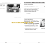
Daily Prestarting Checks . . . . . . . . . . . . . . . . . . 25-1 Bleeding the Fuel System (Engines With
Lubrication & Maintenance/500 Hour/12 Month Electronic Fuel Systems And Bosch VP44
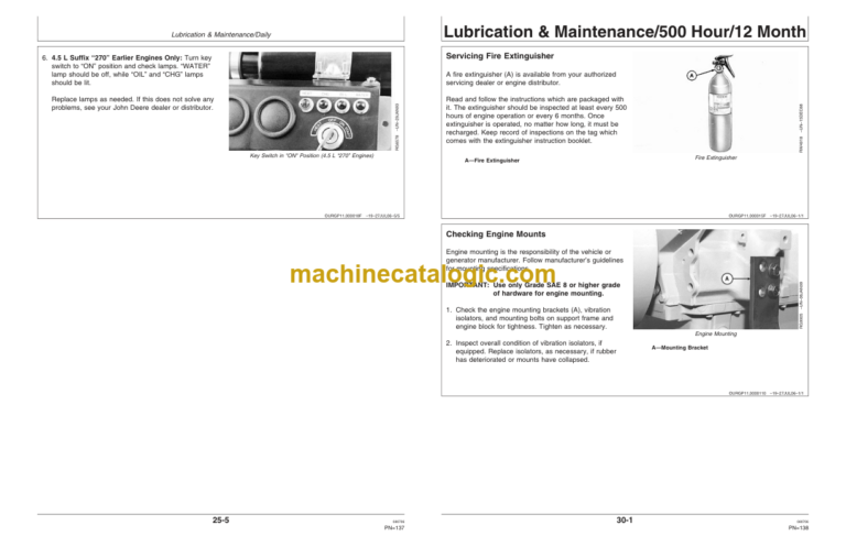
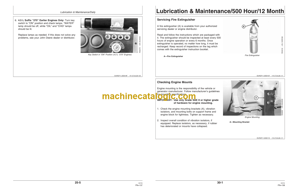
Servicing Fire Extinguisher . . . . . . . . . . . . . . . . . 30-1 Pump) . . . . . . . . . . . . . . . . . . . . . . . . . . . . . . 40-12
Checking Engine Mounts . . . . . . . . . . . . . . . . . . 30-1 Bleed the Fuel System (Engines with
Servicing Battery . . . . . . . . . . . . . . . . . . . . . . . . 30-2 Electronic Fuel Systems and Stanadyne DE10
Manual Belt Tensioner Adjustment . . . . . . . . . . . 30-4 Pump) . . . . . . . . . . . . . . . . . . . . . . . . . . . . . . 40-14
Manual Belt Tensioner Adjustment Using Bleed the Fuel System (Engines with
Belt Tension Tool (Alternate Method Electronic Fuel Systems and Denso High
For Engines Without Auxiliary Drive). . . . . . . . 30-5 Pressure Common Rail) (4045HF475,
Changing Engine Oil and Replacing Filter . . . . . 30-7 6068HF475) . . . . . . . . . . . . . . . . . . . . . . . . . 40-17
Checking Crankcase Vent System . . . . . . . . . . . 30-9 Bleed the Fuel System (4045DF270,
Checking Air Intake System . . . . . . . . . . . . . . . 30-11 4045TF270) . . . . . . . . . . . . . . . . . . . . . . . . . 40-19
Replacing Fuel Filter Elements. . . . . . . . . . . . . 30-12
Checking Belt Tensioner Spring Tension Troubleshooting
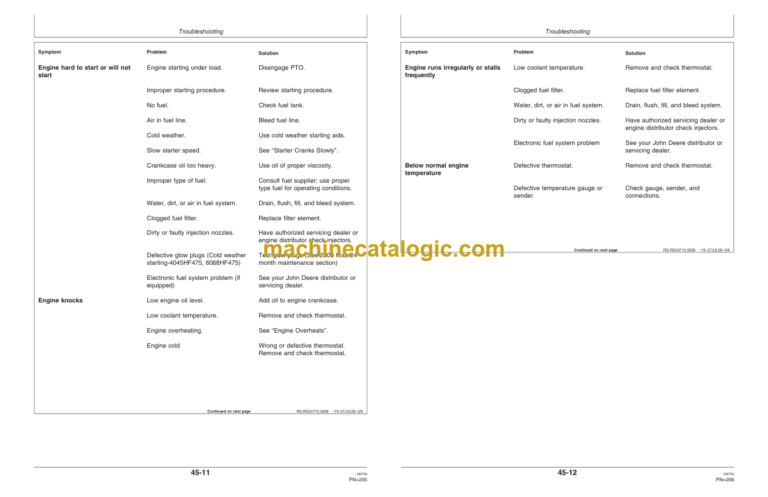
and Belt Wear (Automatic Tensioner) . . . . . . 30-14 General Troubleshooting Information . . . . . . . . . 45-1
Checking Engine Electrical Ground
Precautions For Welding On Engines
Connections . . . . . . . . . . . . . . . . . . . . . . . . . 30-16
Checking Cooling System. . . . . . . . . . . . . . . . . 30-16 Equipped With Electronic Engine Control Unit
Replenishing Supplemental Coolant (ECU) . . . . . . . . . . . . . . . . . . . . . . . . . . . . . . . 45-2
Additives (SCAs) Between Coolant Precautions for Electrical System When
Changes . . . . . . . . . . . . . . . . . . . . . . . . . . . . 30-17 Steam Cleaning Engine . . . . . . . . . . . . . . . . . 45-2
Testing Diesel Engine Coolant . . . . . . . . . . . . . 30-19 Engine Wiring Layout (Electronic Fuel
Pressure Testing Cooling System. . . . . . . . . . . 30-20 System With Stanadyne DE10 Injection
Checking and Adjusting Engine Speeds . . . . . . 30-21 Pump) . . . . . . . . . . . . . . . . . . . . . . . . . . . . . . . 45-3
Engine Wiring Layout (Electronic Fuel
Lubrication & Maint./2000 Hour/24 Month System With Bosch VP44 Injection Pump) . . . 45-4
Adjusting Variable Speed (Droop) — 4.5
L “270” Generator Set Engines Only . . . . . . . . 35-1 Continued on next page
ii 080706
PN=2
Contents
Page Page
Engine Wiring Layout (Electronic Fuel Lubrication and Maintenance Records
System With Denso High Pressure Common Using Lubrication and Maintenance Records . . . 60-1
Rail)(4045HF475,6068HF475). . . . . . . . . . . . . 45-5 Daily (Prestarting) Service . . . . . . . . . . . . . . . . . 60-1
Engine Wiring Diagram (With Earlier 500 Hour/12 Month Service . . . . . . . . . . . . . . . . 60-2
Electronic Instrument Panel) . . . . . . . . . . . . . . 45-6 2000 Hour/24 Month Service . . . . . . . . . . . . . . . 60-3
Engine Wiring Diagram (Engines With Service as Required . . . . . . . . . . . . . . . . . . . . . . 60-4
Electronic Instrument Panel) . . . . . . . . . . . . . . 45-7
Engine Wiring Diagram (With Later Emission System Warranty
Full-Featured Electronic Instrument Panel) . . . 45-8 U.S. EPA Emmission Control Warranty
Engine Wiring Diagram (With Later Statement . . . . . . . . . . . . . . . . . . . . . . . . . . . . 65-1
Full-Featured Electronic Instrument Panel)— Emission Control System Certification Label. . . . 65-2