Format: PDF (Printable Document)
File Language: English
File Pages: 347
File Size: 15.48 MB (Speed Download Link)
Brand: Komatsu
Model: WA700-8 Wheel Loader
Book No: GEN00276-01
Serial No: 70001 and up
Type of Document: Field Assembly Manual
$ 39
00 Index and Foreword
Index
Foreword
Precautions for Field Assembly
Disposal of Removed Parts
10 Work Preparation
Table of Contents
Parts Overview of Main Components (Sales Code: 7XC47)
Dimensions of Main Components (Sales Code: 7XC47)
Assembly Schedule (1/2) (Sales Code: 7XC47)
Assembly Schedule (2/2) (Sales Code: 7XC47)
Workspace and Layout (Sales Code: 7XC47)
Specification Drawing: WA700-8E0
Tool List for Field Assembly
Standard Tightening Torque Table
Coating Materials List
Selection of Wire Ropes Used for Assembly
Selection of Nylon Slings Used for Assembly
Relationship Between Work Number of Assembly Procedure and Packing Tag
How to Use Fuel, Coolant and Lubricants by Ambient Temperature
How to Secure Machine
20 Assembly Procedure
Table of Contents
0050_Place Bare Machine
0101_Place Rear Axle
0102_Place Front Axle
0105_Install Rear Axle Frame
0106_Install Front Axle Frame
0170_Install Fuel Tank Filler Port
0260_Install Center Drive Shaft (Between Center Support and Transmission)
0340_Connect Rear Axle Grease Piping
0351_Connect Drive Shaft Between Engine and Transmission
0420_Install Cab and Floor Assembly
0460_Connect Piping Between Transmission and Area Below Floor
0470_Connect Air Conditioner Drain Hose
0480_Connect and Fix Piping Bellow Cab (Between Hydraulic Tank and Floor)
0485_Connect Piping Below Cab
0490_Connect and Fix R.H. Piping Below Cab
0500_Connect and Fix L.H. Piping Below Cab – 1
0510_Connect and Fix L.H. Piping Below Cab – 2
0520_Connect L.H. Piping Below Cab
0521_Install Chassis Harness of Cab Floor
0530_Connect and Fix Harness Below Cab – 1
0531_Connect and Fix Harness Below Cab – 2
0532_Connect and Fix Harness Below Cab – 3
0534_Fix and Connect Air Conditioner Hose (Below Cab)
0535_Connect and Fix Heater Hose
0536_Install AJSS Stopper
0550_Install Step Light to ROPS Top
0551_Install Wireless LAN to ROPS Top
0552_Install Wireless LAN BULLET
0553_Install GPS Antenna to ROPS Top
0554_Install Iridium Antenna to ROPS Top
0555_Install Wireless LAN, GPS, and Iridium Antenna to ROPS Top – 1
0556_Install Wireless LAN, GPS, and Iridium Antenna to ROPS Top – 2
0557_Install Rear Cover to ROPS Top
0565_Connect ROPS Light Harness
0567_Connect Washer Tank Hose
0575_Install Yellow Revolving Warning Lamp
0576_Install Yellow Revolving Warning Lamp Harness
0577_Install Radio Antenna
0581_Block Fire Extinguisher Installation Position
0610_Install R.H. and L.H. Battery Box Steps (Power Ladder-Less Specification)
0800_Install Ladder Side Cover
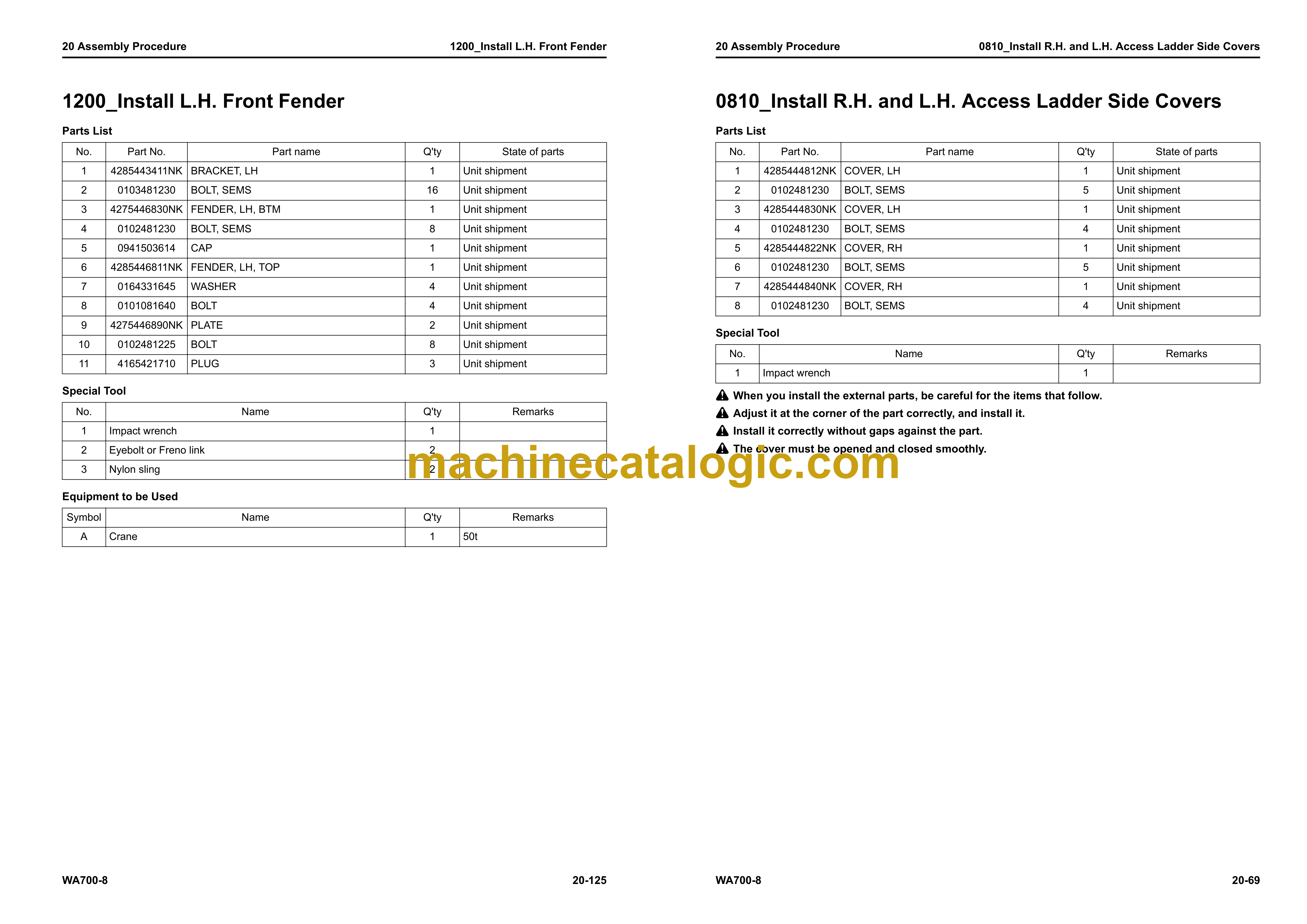
0810_Install R.H. and L.H. Access Ladder Side Covers
0820_Install Mudguard Below Ladder – 1
0825_Install Mudguard Below Ladder – 2
0830_Install Emergency Escape Ladder
0840_Install Counterweight
0850_Install Tow Pin
0880_Install ROPS
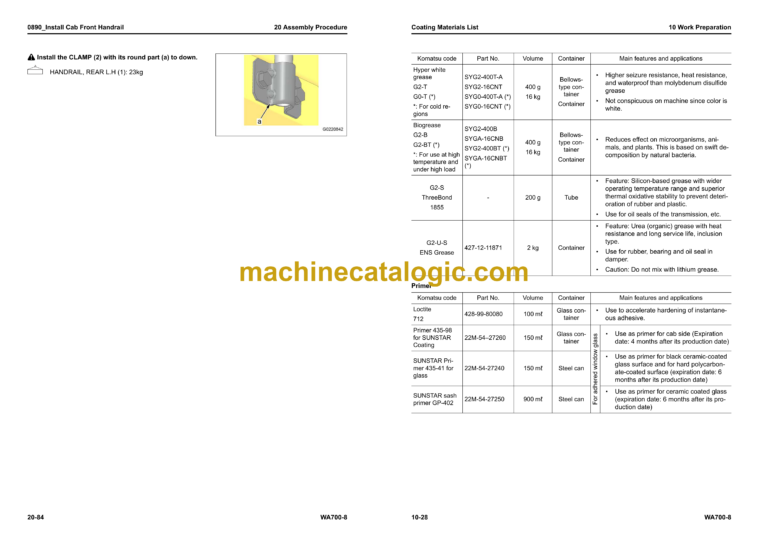
0890_Install Cab Front Handrail
0900_Install L.H. Handrail – 1
0905_Install L.H. Handrail – 2
0910_Install L.H. Handrail – 3
0915_Install L.H. Handrail – 4
0920_Install L.H. Handrail – 5
0925_Install L.H. Handrail – 6
0950_Install R.H. Handrail – 1
0955_Install R.H. Handrail – 2
0960_Install R.H. Handrail – 3
0965_Install R.H. Handrail – 4
0967_Install R.H. Handrail – 4, 5
0970_Install R.H. Handrail – 5
0975_Install R.H. Handrail – 6
0980_Install R.H. Handrail – 7
1100_Install Boom and Bell Crank Assembly
1110_Connect Boom Harness
1120_Install Boom Positioner
1175_Install Lift Cylinder and Boom
1180_Install Bucket – 1
1190_Install Bucket – 2
1197_Attach Boom Decal (Precautions for Maintenance Below Work Equipment)
1199_Attach Boom Decal
1200_Install L.H. Front Fender
1210_Install R.H. Front Fender
1220_Install Mudguards Below R.H. and L.H. Front Fenders
1400_Install Front Frame Cover
1500_Install L.H. Mirror – 1
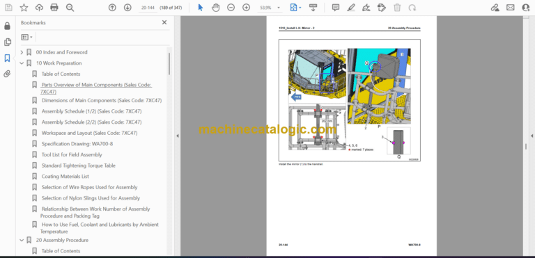
1510_Install L.H. Mirror – 2
1520_Wiring of L.H. Mirror – 1
1530_Wiring of L.H. Mirror – 2
1540_Wiring of L.H. Mirror – 3
1550_Wiring of L.H. Mirror – 4
1560_Wiring of L.H. Mirror – 5
1570_Installation of R.H. Mirror – 1
1580_Installation of R.H. Mirror – 2
1590_Wiring of R.H. Mirror – 1
1600_Wiring of R.H. Mirror – 2
1610_Wiring of R.H. Mirror – 3
1620_Wiring of R.H. Mirror – 4
1630_Wiring of R.H. Mirror – 5
1700_Installation of Front Axle – 1
1710_Installation of Front Axle – 2
1720_Installation of Front Axle – 3
1730_Installation of Front Axle – 4
1760_Installation of Front Axle – 5
1800_Installation of Rear Axle – 1
1810_Installation of Rear Axle – 2
1820_Installation of Rear Axle – 3
1830_Installation of Rear Axle – 4
1840_Installation of Rear Axle – 5
1950_Installation of Bolt Below Battery Box
2000_Installation of KomVision Camera (for Front)
2070_Installation of Side Platform Lamp
2090_Installation of Radiator Guard Lamp
3000_Installation of Exhaust Pipe
3010_Assembly of Air Cleaner
3500_Installation of Tire
3620_Installation of Tire Stopper
4000_Bleed Air from Pump
4010_Charging of Air Conditioner Gas
4020_How to Bleed Air from Brake Circuit
4030_Examine Axle Oil Level, Add Oil
4050_Supply of Grease
4080_Bleed Air from Hydraulic Circuit
4100_Default Setting Adjustment Menu 1
4110_Default Setting Adjustment Menu 2
4120_Default Setting Adjustment Menu 3
4130_Default Setting Adjustment Menu 4
4140_Default Setting Adjustment Menu 5
4150_Default Setting Adjustment Menu 6
4300_Load Meter Unloaded Adjustment 1
4310_Load Meter Unloaded Adjustment 2
4500_Adjustment of AJSS Lever
4510_Measurement of Frame End Stopper Clearance
4600_Adjustment of Bucket Angle
6000_Setting of KomVision System
6010_Preparation of Calibration of KomVision Camera – 1
6020_Preparation of Calibration of KomVision Camera – 2
6030_Preparation of Calibration of KomVision Camera – 3
6100_Calibration of KomVision5 Camera
6250_How to Examine Tire Pressure and Inflate Tire
Machine Check Sheet for Field Assembly
Index

