Format: PDF (Printable Document)
File Language: English
File Pages: 516
File Size: 58.18 MB (Speed Download Link)
Brand: Komatsu
Model: WH609-1, WH613-1, WH713-1, WH714-1, WH714-1, WH716-1 Telescopic Handler
Book No: WEBM005700
Serial No: 395F60001,3, F70001,2,3,4 and up
Type of Document: Shop Manual
$ 39
VEBM720100 PW148-8
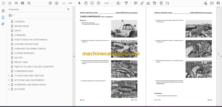
CONTENTS
FOREWORD
Safety
General
How to read the shop manual
Hoisting instructions
Coating materials
Standard tightening torque
Electric wire code
Conversion tables
Units
GENERAL
Specification dimension drawings
Working ranges
Specifications
Weight table
Fuel, coolant and lubricants
STRUCTURE AND FUNCTION
KOMTRAX terminal system
Service brake and suspension system
Steering system
Travel system
1st attachment circuit hydraulic performance (main valve bypassed)
Sensor
Overload warning device
Machine monitor system
Electrical control system
Electrical system
Electrical wiring diagramm
Air conditioner
Work equipment
Dozer cylinder
Outrigger cylinder
Hydraulic cylinder
Boom safety valve
Solenoid valve block
Work equipment – Swing PPC valve
Travel PPC pedal
Centre swivel joint
CLSS
Control valve
Pilot pressure control (PPC) system
Hydraulic pump
Hydraulic tank
Hydraulic circuit diagram
Hydraulic equipment layout drawings
Orbitrol valve
Steering column
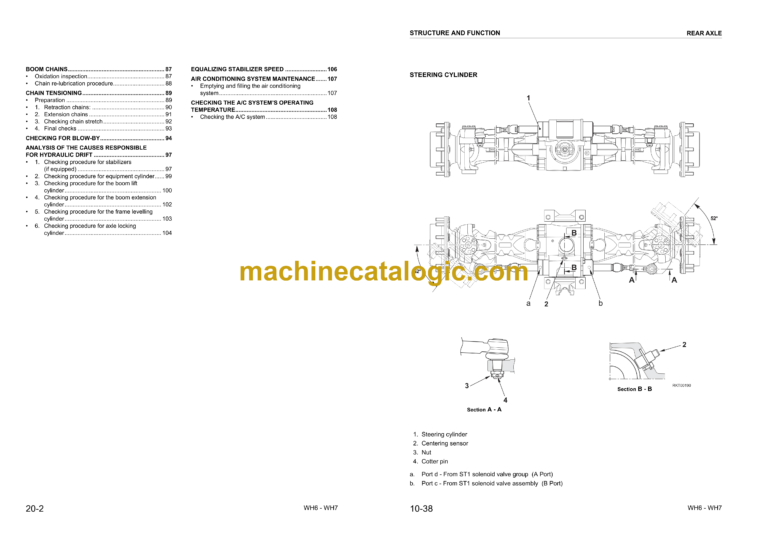
Steering system
Accumulator for brake valve
Power brake valve
Priority valve
Brake/steer pump
Braking system
Suspension lock cylinder
Axle
Clutch control circuit
Travel motor
ATT EPC valve assembly
Shematic
Quick coupler control valve
Transmission
Undercarriage
Swing machinery & motor
Swing circle
Power train
Radiator, oil cooler, aftercooler and fuel cooler
Engine related parts
TESTING AND ADJUSTING
Standard value table for engine related parts
Standard value table for chassis related parts
Checking fuel circuit for leakage
Checking and adjusting air conditioner compressor belt tension
Replacing the fan belt
Measurement of clearance in swing circle bearing
Inspection and adjustment of hydraulic oil pressure in hydraulic circuit for work equipment, swing and travel
Inspection and adjustment of control circuit oil pressure
Inspection and adjustment of pump PC (valve inlet) control oil pressure
Inspection and adjustment of pump LS valve control oil pressure
Measurement of solenoid valve output pressure
Measurement of PPC valve output pressure
Adjustment of work equipment and swing PPC valve
TESTING AND ADJUSTING (100)
Measuring and adjusting quick coupler control valve output pressure
Measuring engine speed
Measuring intake air pressure (boost pressure)
Checking exhaust gas colour
Adjusting valve clearance
Measurement of compression pressure
Measuring blow-by pressure
Measuring engine oil pressure
Handling fuel system parts
Releasing residual pressure from fuel system
Measuring fuel pressure
Measuring fuel return rate and leakage
Bleeding air from fuel circuit
Testing travel motor relief pressure
Adjusting travel motor relief pressure
Testing propshaft speed
Testing transmission clutch control circuit
Inspection of locations of hydraulic drift of work equipment
Release of remaining pressure in hydraulic circuit
Measurement of oil leakage
Air bleeding of various parts
Inspection procedures for diode
Special function of monitor panel
TESTING AND ADJUSTING (220)
Troubleshooting
Points to remember when troubleshooting
Sequence of events in troubleshooting
Points to remember when carrying out maintenance
Checks before troubleshooting
Classification and steps for troubleshooting
Failure-looking phenomenon and troubleshooting no.
Connector location chart and electrical circuit diagram by system
Connection table for connector pin numbers
TESTING AND ADJUSTING (300)
Troubleshooting when failure code is indicated
Before carrying out troubleshooting when failure code is displayed
Information contained in troubleshooting table
Failure code [6B2JMA] – Travel hydraulic abnormality
Failure code [989L00] – Engine controller lock caution 1
Failure code [989M00] – Engine controller lock caution 2
Failure code [989N00] – Engine controller lock caution 3
Failure code [AA10NX] – Air cleaner clogging
Failure code [AB00KE] – Charge voltage low
Failure code [B@BAZG] – Eng oil press. low
Failure code [B@BAZK] – Eng oil level low
Failure code [B@BCNS] – Eng water overheat
Failure code [B@BCZK] – Eng water level low
Failure code [B@HANS] – Hydr oil overheat
Failure code [CA111] – EMC critical internal failure
Failure code [CA115] – Engine neutral and backup speed sensor error
Failure code [CA122] – Chg air press sensor high error
Failure code [CA123] – Chg air press sensor low error
Failure code [CA131] – Throttle sensor high error
Failure code [CA132] – Throttle sensor low error
Failure code [CA144] – Coolant temp sens high error
Failure code [CA145] – Coolant temp sens low error
Failure code [CA153] – Chg air temp sensor high error
Failure code [CA154] – Chg air temp sensor low error
Failure code [CA155] – Chg air temp high speed derate
Failure code [CA187] – Sens supply 2 volt low error
Failure code [CA221] – Ambient press sens high error
Failure code [CA222] – Ambient press sens low error
Failure code [CA227] – Sens supply 2 volt high error
Failure code [CA234] – Eng overspeed
Failure code [CA238] – Ne speed sens supply volt error
Failure code [CA271] – IMV/PCV1 short error
Failure code [CA272] – IMV/PCV1 open error
Failure code [CA322] – Inj #1 (L#1) open/short error
Failure code [CA324] – Inj #3 (L#3) open/short error
Failure code [CA331] – Inj #2 (L#2) open/short error
Failure code [CA332] – Inj #4 (L#4) open/short error
Failure code [CA342] – Calibration code incompatibility
Failure code [CA351] – Injectors drive circuit error
Failure code [CA352] – Sens supply 1 volt low error
Failure code [CA386] – Sens supply 1 volt high error
Failure code [CA428] – Water in fuel sensor high error
Failure code [CA429] – Water in fuel sensor low error
Failure code [CA435] – Eng oil press sw error
Failure code [CA441] – Battery voltage low error
Failure code [CA442] – Battery voltage high error
Failure code [CA449] – Rail press very high error
Failure code [CA451] – Rail press sensor high error
Failure code [CA452] – Rail press sensor low error
Failure code [CA488] – Chg air temp high torque derate
Failure code [CA553] – Rail press high error
Failure code [CA559] – Rail press low error
Failure code [CA689] – Eng Ne speed sensor error
Failure code [CA731] – Eng bkup speed sens phase error
Failure code [CA757] – All continuous data lost error
Failure code [CA778] – Eng bkup speed sensor error
Failure code [CA1633] – KOMNET datalink timeout error
Failure code [CA2185] – Throttle sensor supply voltage high error
Failure code [CA2186] – Throttle sensor supply voltage low error
Failure code [CA2249] – Rail press very low error
Failure code [CA2311] – IMV solenoid error
Failure code [CA2555] – Grid htr relay volt high error
Failure code [CA2556] – Grid heater relay volt low error
Failure code [D110KB] – Short-circuiting in battery relay
Failure code [D19JKZ] – Personal code relay abnormality
Failure code [D862KA] – GPS antenna disconnection
Failure code [DA25KP] – 5V sensor 1 power abnormality
Failure code [DA2RMC] – CAN discon (pump con detected)
Failure code [DAFRMC] – GPS module error
Failure code [DAFRMC] – CAN discon (monitor detected)
Failure code [DDP4KX] – Abnormality in travel PPC pressure switch
Failure code [DDWCKZ] – Abnormality in travel direction control switch
Failure code [DFB1KZ] – 1st ATT service lever main potentio 1 abnormality
Failure code [DFB2KZ] – 2nd ATT service lever main potentio 2 abnormality
Failure code [DFB3L8] – 1st ATT service lever Potentio 1 error
Failure code [DFB4L8] – 2nd ATT service lever potentio 2 error
Failure code [DFB5KZ] – 1st ATT service lever main potentio 1 abnormality
Failure code [DFB6KZ] – Service lever potentio 2 abnormality
Failure code [DGH2KB] – Hydr oil sensor short
Failure code [DH10KS] – Abnormality in 24V sensor power source
Failure code [DHPAMA] – F pump press sensor abnormality
Failure code [DHS5KX] – Abnormality in travel PPC sensor
Failure code [DHX1MA] – Abnormality in overload caution sensor
Failure code [DLT4KA] – Disconnection in transmission speed sensor in pump controller system
Failure code [DW27KA] – Disconnection in transmission clutch solenoid
Failure code [DW27KB] – Short-circuiting in transmission clutch solenoid
Failure code [DW4AKA] – Disconnection in suspension lock solenoid
Failure code [DW4AKB] – Short circuiting in suspension lock solenoid
Failure code [DW4CKA] – Disconnection in PPC lock solenoid
Failure code [DW4CKB] – PPC lock sol. S/C
Failure code [DW4MKA] – Disconnection in creep solenoid
Failure code [DW4MKB] – Short-circuiting in creep solenoid
Failure code [DW44KA] – Disconnection of travel F/R solenoid
Failure code [DW44KB] – Short-circuiting of travel F/R solenoid
Failure code [DW45KA] – Disconnection in swing parking brake solenoid
Failure code [DW45KB] – Swing brake sol. S/C
Failure code [DW91KA] – Disconnection in travel neutral solenoid
Failure code [DW91KB] – Short-circuiting in travel neutral solenoid
Failure code [DWK0KA] – Disconnection in 2-stage relief solenoid
Failure code [DWK0KB] – Short-circuiting in 2-stage relief solenoid
Failure code [DWK2KA] – Disconnection in 2-stage back pressure solenoid
Failure code [DWK2KB] – Short circuiting in 2-stage back pressure solenoid
Failure code [DXA8KA] – Disconnection in PC-EPC (F) solenoid system
Failure code [DXA8KB] – Short-circuiting in PC-EPC (F) solenoid
Failure code [DXE0KA] – Disconnection in LS-EPC solenoid system
Failure code [DXE0KB] – Short-circuiting in LS-EPC solenoid
Failure code [DXE4KA] – 1st service current EPC discon (left hand)
Failure code [DXE4KB] – 1st service current EPC short (left hand)
Failure code [DXE7KA] – 1st service current EPC discon (right hand)
Failure code [DXE7KB] – 1st service current EPC short (right hand)
Failure code [DXE8KA] – 2nd service current EPC discon (left hand)
Failure code [DXE8KB] – 2nd service current EPC short (left hand)
Failure code [DXE9KA] – 2nd service current EPC discon (right hand)
Failure code [DXE9KB] – 2nd service current EPC short (right hand)
Failure code [DY20KA] – Wiper working abnormality
Failure code [DY20MA] – Wiper parking abnormality
Failure code [DY2CKA] – Washer drive discon
Failure code [DY2CKB] – Washer drive short
Failure code [DY2DKB] – Wiper drive (for) short
Failure code [DY2EKB] – Wiper drive (rev) short
TESTING AND ADJUSTING (520)
Troubleshooting of electrical system (E-Mode)
Preparations for troubleshooting of electrical system
Troubleshooting of electrical system (E-mode)
Information contained in troubleshooting table
E-1 When starting switch turned ON, machine monitor displays nothing
E-2 When starting switch turned ON (before starting engine), basic check item lights up
E-3 Engine does not start (engine does not rotate)
E-4 Preheater does not operate
E-5 Automatic warm-up system does not operate (in cold season)
E-6 All work equipment, swing and travel mechanism do not move or cannot be locked
E-7 Precaution lights up while engine is running
E-8 Emergency stop item lights up while engine is running
E-9 Engine coolant temperature gauge does not indicate normally
E-10 Hydraulic oil temperature gauge does not indicate normally
E-11 Fuel level gauge does not indicate normally
E-12 Contents of display by machine monitor are different from applicable machine
E-13 Machine monitor does not display some items
E-14 Function switch does not work
E-15 Auto-decelerator does not operate normally
E-16 Working mode does not change
E-17 Travel speed does not change
E-18 Alarm buzzer cannot be stopped
E-19 Windshield wiper and window washer do not operate
E-20 Power maximising function does not operate normally
E-21 Swing holding brake does not operate normally
E-21 – “Boom/Stabiliser RAISE” is not correctly displayed in monitor function
E-22 Travel alarm does not sound or does not stop sounding
E-23 Air conditioner does not operate normally (including air conditioner abnormality record)
E-24 When starting switch is turned OFF, service meter is not displayed
E-25 Machine monitor cannot be set in service mode
E-26 Monitoring function does not display lever control signal normally
E-27 KOMTRAX system does not operate normally
TESTING AND ADJUSTING (600)
Troubleshooting of electrical system (Error checking of items without monitor codes)
TESTING AND ADJUSTING (710)
Troubleshooting of engine (S-MODE)
Troubleshooting of hydraulic and mechanical system (H-MODE)
DISASSEMBLY AND ASSEMBLY
How to read this manual
Coating material lists
Special tools list
Sketches of special tools
List of tools
Precautions when performing operation
Removal and installation of fuel supply pump assembly
Removal and installation of fuel injector assembly
Removal and installation of front oil seal
Removal and installation of rear oil seal
Removal and installation of cylinder head assembly
Removal and installation of fuel cooler assembly
Removal and installation of combination cooler assembly
Removal and installation of engine and hydraulic pump assembly
Removal and installation of engine hood assembly
Removal and installation of travel motor
Disassembly and assembly of travel motor assembly
Removal and installation of swing motor and swing machinery
Removal of swing motor assembly
Disassembly and assembly of swing motor and swing machinery
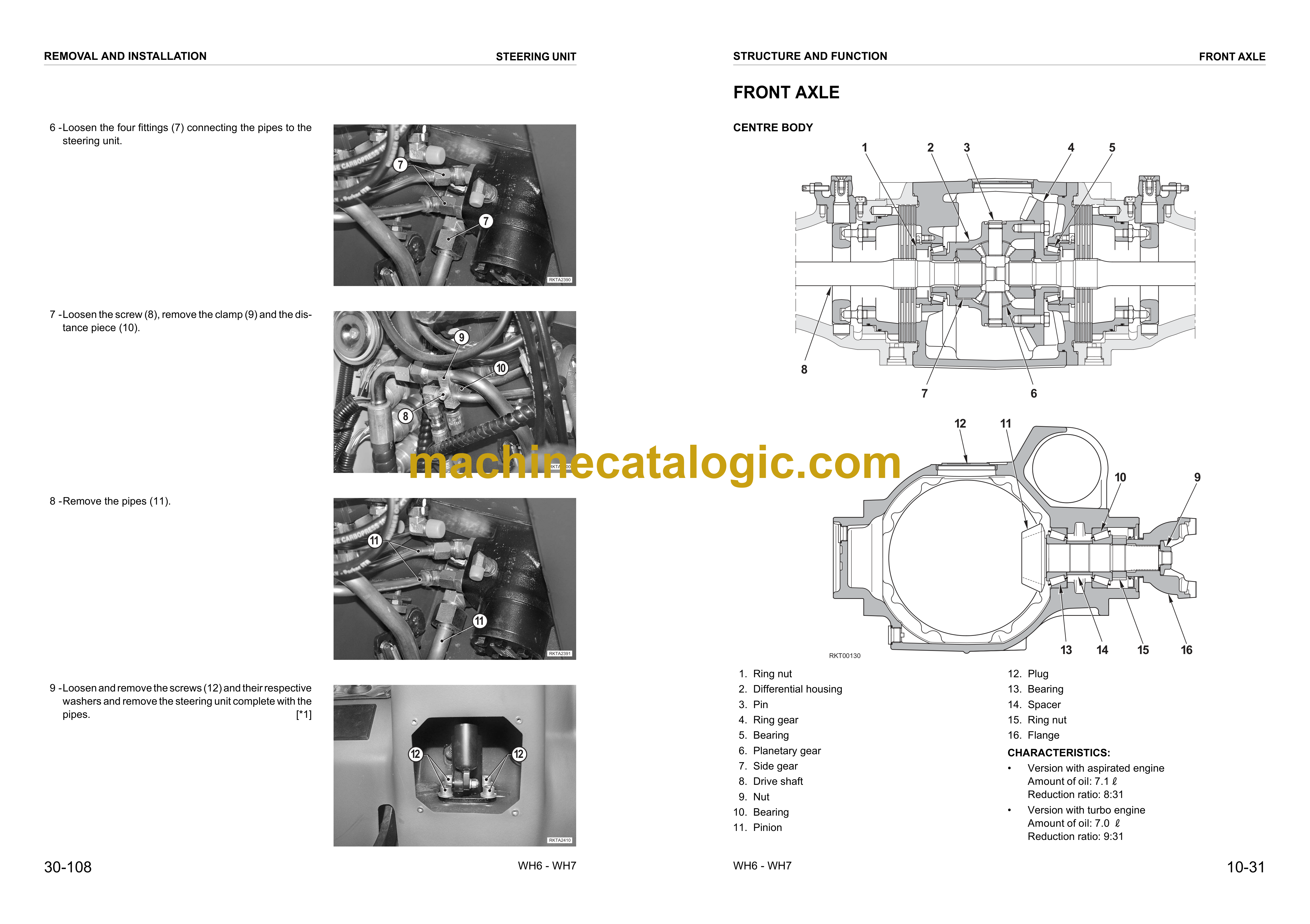
Removal and installation of front axle assembly
Disassembly and assembly of front axle
Removal and installation of rear axle and transmission
Disassembly and assembly of rear axle assembly
Disassembly and assembly of transmission
Removal and installation of propshaft assembly
Removal and installation of wheel
Removal and installation of suspension lock cylinder assembly
Disassembly and assembly of suspension lock cylinders
Removal and installation of outrigger assembly
Disassembly and assembly of outriggers
Removal and installation of dozer blade assembly
Disassembly and assembly of dozer blade
Removal and installation of swing circle assembly
Removal and installation of revolving frame assembly
Removal and installation of centre swivel joint
Disassembly and assembly of centre swivel joint assembly
Removal and installation of fuel tank assembly
Removal and installation of hydraulic tank assembly
Removal and installation of control valve assembly
Removal and installation of LS separation valve assembly
Removal and installation of pressure compensation valve assembly
Removal and installation of main relief valve assembly
Removal and installation of LS control EPC valve
Removal and installation of PC EPC valve assembly
Removal and installation of PPC valve block assembly
Removal and installation of oil seal in hydraulic pump input shaft
Disassembly and assembly of work equipment PPC valve
Disassembly and assembly of hydraulic cylinder
Removal and installation of monoboom work equipment
Removal and installation of 2 piece boom work equipment
Removal and installation of air conditioner unit
Removal and installation of counterweight
Removal and installation of operator cab assembly
Removal and installation of monitor assembly
Removal and installation of pump controller assembly
Removal and installation of engine controller assembly
Removal and Installation of KOMTRAX terminal
OTHER
Hydraulic circuit diagram (1/3)
Hydraulic circuit diagram (2/3)
Hydraulic circuit diagram (3/3)
Electrical circuit diagram (cabin 1/4)
Electrical circuit diagram (cabin 2/4)
Electrical circuit diagram (cabin 3/4)
Electrical circuit diagram (cabin 4/4)
Electrical circuit diagram (machine 1/4))
Electrical circuit diagram (machine 2/4))
Electrical circuit diagram (machine 3/4))
Electrical circuit diagram (machine 4/4))
Connector diagramm 1/5
Connector diagram 2/5
Connector diagram 3/5
Connector diagram (4/5)
Connector diagram (5/5)
