Case 5130-7130 Series Axial-Flow Combine Index:
Binder Cover
Acronyms
_Sec 01 Introduction
Purpose Of The Training Manual
Use Of This Manual
Production Software
Software Version
Controller
Cab Display – Pro-700
Serial Number Plates
Machines equipped with CXCM controller
Machines equipped with UCM controller
Grain Headers
Pick Up Headers
Corn Headers
Headers
Draper Headers
Service Information
Support Information
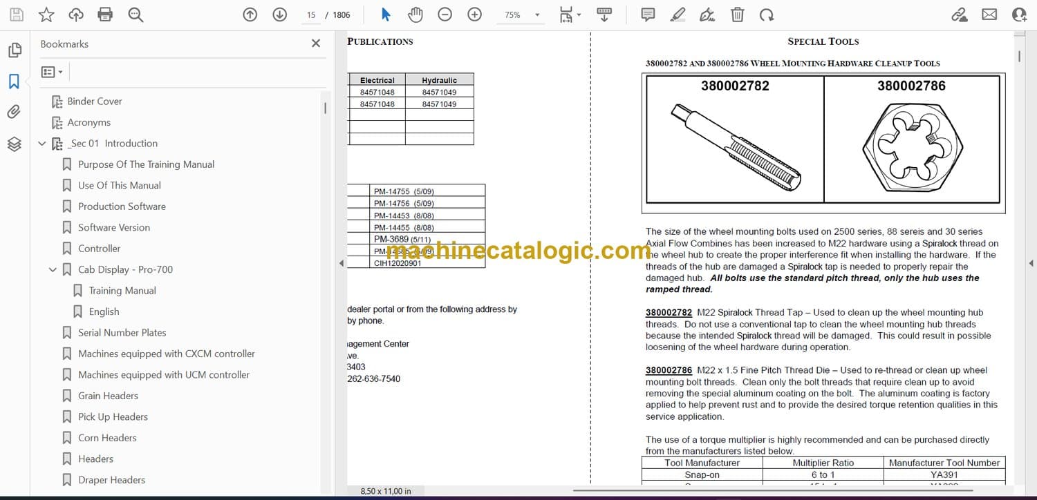
380002782 and 380002786 Wheel Mounting Hardware Cleanup Tools
¾ Inch Torque Wrench Stand
1 Inch Torque Wrench Stand
380002781 Shaker System Alignment Kit
Shaker Bushing Replacing Kit
PTO Gearbox Tools
Setting Tool
Rotor Drive Alignment Tool
84128607 HD Torque Sensing Unit Spring Compression Plate (88 and 30 series)
PTO Gear Box
Engine Tools
Engine Belt Installation, 380002816
Engine Harness Repair Kit, 380040231
Engine Tools
380040195 Kit
Fuel Pressure Test, 38010055
Programming Header Types
Accumulator Charging Tools
Software Loading Harness – 380002497
Power/Data Download Cable for GPS and Nav II Controllers – 380002422
380003213 Telematics Ethernet Communication Cable
Data Connection Extension
_Sec 11 Engine
Section 11 CNH (FPT) 9L Engine
Table Of Contents
Purpose Of The Training Manual
Major Changes
Component
Supply Voltage
Working Range
Resistance:
Ohms at
70oF (21oC)
Grid Heater Performance
Heater Activation
Specification
Cursor 6.7 Engine – 5130
Description
Specifications
Cursor 9 Engine – 6130 & 7130
Description
Specifications
Specification
Model
6130
7130
Displayed
% of Power
Model
5130
Displayed
% of Power
Major Features:
General Information
Engine Control Unit Module
All Neutral
Separator Engaged
Engine High Idle Information
Transmission Gear: 3rd Selected
General Information
The following sensor failures will also cause a torque reduction:
Operator Control Center
Cab Display
Throttle Control
Components and Location
Air Filter Restriction
Engine Control Unit
Components and Location
Engine Sensors
Fuel Supply
Components and Location
Components and Location
Components and Location
Components and Location
ECU (Engine Control Unit) Name Plate
Engine Plate
Components and Location
Crankcase Breather
DEF Controls
Electrical Supply
SCR Components
Fuel and DEF Supply
DEF Heating & Supply
SCR Components
Air Intake Monitoring
DEF Injecting
SCR Components
SCR Temperature Monitoring
Exhaust Monitoring
Information Flow
Throttle Control, B-60
Unloading Auger engagement, MFH
Engine Communications
Wait To Start Indicator
Engine Communications
UCM
Fuel Filter Clogged Sensor, S-422
Air Filter Restriction, S-309
Engine Communications
UnSwitched B+, 30amp
Switched, 5amp
Engine Communications
ECU, con’t
Ambient Air Pressure Sensor
Water In Fuel (WIF), R-357
Grid Heater, R-001
Inlet Air Temperature & Humidity Sensor, B-607
Engine Communications
ECU, con’t
Intake Manifold Temperature (IMT)
Engine Oil Pressure
Engine Communications
ECU, con’t
Engine Oil Pressure / Temperature, Sen-FPT9
Pressure
Temperature
Engine Communications
Engine Control Unit, (ECU)
Coolant Temperature Sensor, SEN-FPT7
Engine RPM, Sen-FPT5
Engine Communications
Engine Control Unit, (ECU) con’t
Engine Camshaft Position Sensor, Sen-FPT6
Engine Boost Pressure / Intake Temperature, Sen-FPT8
Pressure
Temperature
Engine Communications
Fuel Actuators 1-6, SOL-CYL1-6, (Injector)
Engine Communications
Key Switch Controls
Key Switch “OFF”
Engine Starting
Key Switch “RUN”
Engine Starting
Key Switch “Start”
Operation
Starting Aids
Circuit Information
Operation
Circuit Testing
Fuel System
Fuel System
Key Switch in the “ON” position, “Engine NOT Running”
Key Switch in the “ON” position, “Engine Running”
Fuel System
Charge Pump
High Pressure Pump
Fuel System
High Pressure Components
Items to investigate:
Steps to Follow
How To Monitor For Power
Engine Overheating State
Engine Air Filter State
Engine Degradation Level
Engine Oil Pressure
Engine Load
Coolant Temperature
Air Intake Temperature
Air Intake Pressure
Engine Oil Pressure
How To Monitor For Power
Fuel Supply
“System with a Screw on Filter base”
9L Filter Base
6.7L Filter Base
How To Monitor For Power
“EST” Screen
“EASY” Engine Program
First the Display
What is a bar
How To Monitor For Power
Step 3: Electronic Service Tool (EST)
Turbo Boost Pressure, con’t
Final Reading
Normal Boost Pressure
How To Monitor For Power
Step 3: Electronic Service Tool (EST), Con’t
What can cause the condition
Pressure Below Commanded
Pressure Above Commanded
Chassis SCR Connections
SCR Electrical Operation
MRR – SCR Electrical Operation
SCR Components
MRR – SCR Electrical Operation
Reference Schematic Frames:
Key components in circuit:
General
Key “OFF”
12V Power
Ground
MRR – SCR Electrical Operation
SCR Electrical, con’t
Key “ON”
12V
DCU
MRR – SCR Electrical Operation
SCR Electrical, con’t
AdBlue Tank Temp & Level Sensor (B-602)
Urea Dosing Valve (Y-605)
Urea Heating Valve (Y-612)
Upstream Exhaust Temperature Sensor (B-603)
Downstream Exhaust Temperature Sensor (B-604)
SCR Electrical Operation
Mid-Range SCR Electrical (cont’d.)
NOx Sensor and CAN3
Word Bookmarks
_Sec 13 SCR Treatment
Mid-Range Step Voltage Transformer
Out Put Voltage
Supply Voltage
Amp.
Temperature
Flagship Battery Equalizer
Out Put Voltage
Supply Voltage
Amp.
Temperature
Line Repair Parts
Tier IV Emission Regulation
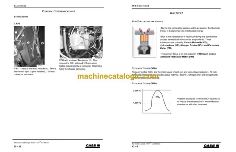
How Pollutants are formed
Nitrogen Oxides (NOx)
Nitrogen Oxides (NOx).
PM Particulate Matter
Two Tier IVa Technologies to Meet the Goal
CEGR
SCR
How CEGR Works (External EGR)
Diesel Particulate Filter (DPF) Components
How SCR Works
What is DEF?
Physical Properties of DEF
DEF Purity
What happens if DEF is blended with tap water or Ag urea?
DEF Quality
DEF Storage
Container Date Code
DEF Safety
System over view
DEF Storage Tank
DEF Storage Tank (cont’d)
DEF Level / Temperature Sensor
DEF Level / Temperature Sensor (cont’d)
DEF Heater Control Valve
DEF Heater Control Valve (cont’d.)
DEF Heating Modes
DEF Heating Modes (cont’d)
DEF Supply Module
DEF Supply Module
Dosing Module
Dosing Module
Mixing Chamber
Filters
Inline Filter, (3)
Filters
Filters
Dosing Module Filter
SCR Catalyst
Temperature Sensors
New Temperature Sensors
NOx Sensor and NOx CAN bus module
Intake Air Temperature/Humidity Sensor
Electrical Transformer
Electrical Control System
DEF Flow and Control
Start Up/ System Operation
Normal Operation
After Run
Anti Tamper Protection
System De-rates
Low DEF level
Poor DEF Quality (NOx cannot be controlled)
Technical Failure of the system (something broken).
System De-rates (cont’d)
System De-rates (cont’d)
System De-rates (cont’d)
System De-rates (cont’d)
Symbols for DEF system:
_Sec 14 Air Compressor
Section 14 Air Compressor
Table Of Contents
Compressor
Component
Working Range
Pressure Regulating Valve
Component
Working Range
Distribution
Component
Working Range
Components and Location
Pressure Regulator Valve, (Governor)
Flag Ship Machines
Mid- Range Machines
Compressor & Ports
System Operation
Key components in circuit:
System Operation
System Operation
Pump Operation
Lubrication
Cooling
Air
System Operation
Displacement Chamber Valve “OPEN”
Displacement Chamber Valve “Closed”
System Operation
Pump Head Operation
Reed Valves
Displacement Valve and Control
Displacement Chamber
System Operation
System Operation
Pressure Regulator Operation
Signal Circuit
Main Relief, Exhaust
Signal Line
Test Fittings
# 1 Signal Pressure Setting
Test Procedure
Test Results
Adjustment
Regulator Adjustment
Regulator
# 2 System Exhaust Pressure Setting
Test Procedure
Test Results
Adjustment
Word Bookmarks
_Sec 2 – GH-2145-12 2012 Sales Support Materials
_Sec 25 Trans Final Drives
Components
Service Brakes (2)
Brake Pressure Switch, S-39
Pedal Release Stop Adjustment
Pedal Full Travel Adjustment
Valve Spool Adjustment
Service Brake Valve
Brake Light Operation
Reference Material:
Key Components:
General Information
Operations:
Valve Ports
General
General
Neutral
Brake Engaged
Park Brake Engaged
Park Brake Disengaged
General
Operation
CAUTION
Normal Operation
Park Brake Electrical Circuits
Reference Material:
Key Components:
Electrical Circuit
Operator Releasing the Brake
_Sec 27 PTO
Section 27 PTO Gear box
Starting Pin:YDG009296
Table Of Contents
Mechanical Drives
Lubrication and Cooling
Components cont’d
Lubrication and Cooling
Components cont’d
Lubrication and Cooling
Components cont’d
Lubrication and Cooling
Lubrication and Cooling
Lubrication and Cooling
Lubrication and Cooling
Lube flow on PTO gearbox cont’d
Lubrication and Cooling
Lubrication and Cooling
Pressurizing the valve from the end.
Testing
Relief Valve
Test Procedure
PTO Cooler Relief Valve
Testing
Pump Flow
Word Bookmarks
_Sec 29 Hydrostatic Drive
Section 29 Hydrostatic Drive
Starting Pin: YDG009296
Table Of Contents
Reservoir And Filtration
Hydraulic Reservoir
Filtration System
Oil Cooler
Oil Cooler Bypass
System Components And Function
System Components And Function
Charge Pump
Models
Approx. GPM
Spacer Plate Thickness
Charge Pressure Relief Valve
System Components And Function
System Components And Function
Models
Displacement
Approx. GPM
Models
Motor Port
Hydrostatic Pump
System Components And Function
Directional Control Valve
Internal Pressure Override (IPO) Control
Servo Pistons & Swashplate
Rotating Group
Fixed Displacement Motor
System Components And Function
Swashplate
Rotating Group
System Components And Function
System Components And Function
Motor Control Valve
High-pressure Relief Valves
Shuttle Valve
Shuttle Relief Valve
System Components And Function
System Components And Function
Two Speed Hydrostatic Motor
Motor Control Valve
Response Valve
System Operations
System Operations
Charge and Shuttle Pressure Relief
System Operations
Charge and Shuttle Relief Valve Operation
Operation Below Relief Pressure
Valve Starting To Open
Valve On Relief
System Operations
System
Directional Control Valve Operation
Neutral
Forward
Reverse
System Operations
System Operations
Forward
System Operations
System Operations
Forward, continued
System Operations
System Operations
Reverse
Single Speed Motor In “FORWARD” Drive
High-pressure Relief Systems
Internal Pressure Override Control (IPO)
Operating Characteristics
High-pressure Relief Systems
Single Speed Motor In “FORWARD” Drive
High Pressure Reliefs
Pressure Below Relief
System On Relief
Two Speed Hydrostatic Motor
Third Gear Lock-Out Switch
Reference:
Power
Low Speed
Switch, ICP
High Position
Switch, ICP
Two Speed Motor
Two Speed Hydrostatic Motor
Response Valve Assembly
Two Speed Hydrostatic Motor
Two Speed Hydrostatic Motor
Response Valve Assembly
Two Speed Hydrostatic Motor
Table Of Contents
If the combine is equipped with a Power Guide Axle
Test Procedures
Test Procedures
Test and Adjusting Procedures
Test and Adjusting Procedures
Test and Adjusting Procedures
Test and Adjusting Procedures
Test and Adjusting Procedures
Adjustment Of Propulsion Control
Test Procedure:
Control Lever Replacement
Test #1 – Charge Pressure
Test Procedure:
Test #1 – Charge Pressure
Test #2 – Servo Pressure
Test Procedure:
Test #3 – Two Speed Motor Servo Pressure
Test Procedure:
Test #3 – , Two Speed Motor Servo Pressure
Test #4 – Internal Pressure Override Valve (IPO)
Test Procedure:
Test
Results: If the drive pressure is not correct, adjust the shims pack in the IPO valve.
Test #5 – Drive Pressure
Test Procedure:
Power Guide Axle
Power Guide Axle
Features
Third Gear Lock-Out Switch
Reference:
Power
Ground
Third Gear Lockout Switch, S-017
Disengaged
Switch, ICP
Power Guide Axle Electrical Operation
Engaged
Switch, ICP
Engaged, HIGH Speed
Supply
Wheel Motor
PGA Control Valve
Fluid Flow
Power Guide Axle
System Components and Functions
Supply Circuit
Power Guide Axle Valve (PGA Valve)
Wheel Motors
Flush Circuit
Low Pressure Shuttle
Power Guide Axle Valve
Low Pressure Shuttle (Pilot Oil)
Power Guide Axle Valve
Power Guide Axle Valve
Power Guide Axle Valve
Dis-Engaged
Power Guide Axle Valve
Power Guide Axle Valve
Intermediate Position
Power Guide Axle Valve
Power Guide Axle Valve
Engaged Position
Reverse
Power Guide Axle Valve
“Engaged Position”
Power Guide Axle Valve
Engaged Position
Forward
Power Guide Axle Valve
One Piece Flow Dividers
Split Flow Dividers (system III only)
Split Flow Divider Spool
Cam Lobe Motor
Two Speed Valve Operation
Reference Material:
Key Components:
PGA Engaged in “HIGH TORQUE” Drive (example FORWARD)
Two Speed PGA Valve Hydraulic
Two Speed Valve Operation, con’t
PGA Engaged in “LOW TORQUE” Drive
Cam Lobe Motor
Notes
Test Procedures
At 39(C (100(F) And High Idle
Test Procedures
Driving Test
Test Procedure
Results
Test Procedures
Isolating The Problem, con’t
Electrical Operation
Test Procedure
Results
Test Procedure
Results
Test Procedures
Low Pressure Shuttle Valve
Test Procedures
Pilot (Charge) Pressure
Test Procedure:
Results:
Test Procedures
Test Procedures
Solenoid Valve Operation
Test Procedure:
Results
Test Procedures
Selector Spool Operation
Test Procedures
Selector Spool Operation
Test Procedure:
Results
Test Procedures
Wheel Motor Leakage
Test Procedures
Wheel Motor Leakage
Test Procedure:
Test Results
Word Bookmarks
_Sec 2B – 2013 PI GH-2117-12
_Sec 2C – 2013 Options GH-2142-12
_Sec 35 General Hydarulic
Purpose Of The Training Manual
Use Of This Manual
Flow Across a Restriction
Pilot Operated Hydraulic System
Out Side View
Bottom Side View
Top Side View
End View
Front End Back End
Feeder to Header Coupler
10-30 Series Flagship
30 Series MRR
88 Series
Function
Back Pressure Valve
Hy-Tran Ultraction
Line Legend
Hydraulic Component Locations
Oil Supply
Pressure Screen
Filtration
Cooling
Cooling
Cooler By-Pass Valve
Cooling Schematic
Cooling Operation
Hydraulic Schematic
PFC Piston Pump
PFC Piston Pump
PFC Pump Operation
Pump Compensator
Low Pressure Standby
Low Pressure Standby
Pressure and Flow Compensation
Pressure and Flow Compensation
High Pressure Standby
High Pressure Standby
Electrical Monitoring Circuits
Hydraulic Oil Temperature Switch
Reservoir Tank Level Switch
Main Machine Stack Valve
Steering Priority Valve
Steering Hand Pump
NA Model
Creepage
Euro Model
Steering Hand Pump
Steering Neutral
Power Turn (left or right)
Manual Steering
Manual Turn (left or right)
Cylinder
Sensor Alignment
Steering Sensor Operation
Back Pressure Valve
Regulated Pressure Valve
Regulated Pressure Valve Operation
Electrical Monitoring Circuits
Park Brake Pressure Switch
SAS Pump
Vacuum Operation
SAS Operation
Sucrose Brush Kit
Test Procedure
Test Procedure
Test Procedure
Relief Valve Location
Test Port
Test Procedure
Test Procedure
Terrain Tracker Counterbalance Valve
Vacuum Fan Motor Relief
Feeder Lift Cylinder Thermal Relief Valve
PTO Gearbox Cooling Relief Valve
SAS Relief Valve
Back Pressure Valve
Test Procedure
Test Procedure
Test Procedure
If Flow Is Below Specifications
Test Procedure
Testing Information
Test Results:
Testing Information
Test Results:
_Sec 39 Hyd Schematics 24 x 36
_Sec 40 Pro-700 Downloading
Word Bookmarks
_Sec 41 EST TIER IV
_Sec 42 Configurations
Section 42 Calibration & Configurations
Table Of Contents
Machine Calibrations
30 Series (5130, 6130, 7130) Machine Configurations
Product Identification Configurations
ICP Configurations
30 Series (5130, 6130, 7130) Machine Configurations
Machine Configurations
_Sec 51 Connector Guide Complete
Connector Types and Styles 2
Connector removal and installation 3
Terminal Pin Identification 3
Amp Superseal Connectors 6
Connector removal and installation 6
Terminal Pin Identification 6
Deutsch “Strike” Connectors 8
Removal Tool 8
Pin Locations 9
Disassembly 10
Round Tab Connector Removing Terminal Locking Plate 10
Flat Tab Connector Removing Terminal Locking Plate 10
Connector Numbers & Parts 12
Controller Connector Locations 26
UCM Connector Location 26
Main Cab Connection – Right Side 27
Main Cab Connection – LEFT SIDE 27
PTO Gearbox Bulkhead 28
Main SCR Supply Harness 29
_Sec 51 Connector Guide
Starting PIN: YDG009296
Amp Superseal Connector
APEX 2.8mm in line connectors
Deutsch “Strike” Connector
Connector removal and installation
Terminal Pin Identification
Terminal removal
Terminal Insertion
Terminal Parts and Crimping instructions
Connector removal and installation
Terminal Pin Identification
Terminal removal
Terminal Insertion
Terminal Parts and Crimping instructions
Removal Tool
Pin Locations
Disassembly
Round Tab Connector Removing Terminal Locking Plate
Flat Tab Connector Removing Terminal Locking Plate
Terminal Removal
UCM Connector Location
Main Cab Connection – Right Side
Main Cab Connection – LEFT SIDE
PTO Gearbox Bulkhead
Main SCR Supply Harness
Connector X001, Hydraulic Valves
Connector X002, Feeder Harness
_Sec 53 Electrical Schematics
Component Legend
“A” – Control Modules
Sheet
Function
No.
“B” – Sensors
Sheet
Function
No.
Sheet
Function
No.
“d” – Diode Modules
Sheet
Function
No.
Sheet
Function
No.
“E” – Lights
Sheet
Function
No.
Sheet
Function
No.
“F” – Fuses
Function
No.
Sheet
“G” – Power Supplies
Sheet
Function
No.
Sheet
Function
No.
“H” – Speakers
Sheet
Function
No.
Sheet
Function
No.
“J” – Power Oulets
Sheet
Function
No.
Sheet
Function
No.
“K” – Relays
Sheet
Function
No.
Sheet
Function
No.
“M” – Motors
Sheet
Function
No.
Sheet
Function
No.
“R” – Resistors
Sheet
Function
No.
Sheet
Function
No.
“S” – Switch
Sheet
Function
No.
Sheet
Function
No.
“W” – Splice Modules
Sheet
Function
No.
Sheet
Function
No.
“Y” – Solenoids
Sheet
Function
No.
Sheet
Function
No.
Wire identification Information
Wire Size Chart
GND Location
The following pages are the Electrical Schematic; they are identified by their “sheet” numbers located in the bottom right corner.
MRR_Sec 55 Electrical Circuit
Starting Pin#: YDG009296
Batteries
Grain Loss Interface Module – “GLIM”
Major Connections
Main Cab Connection – Right Side
Main Cab Connection – Left Side
Main Power & Ground
Fuse / Relay Panel
Power Distribution Center
Right Hand Console
Controllers
Controllers
Right Hand Console
Controllers
HVAC Module, A-128
Over Head Switch Panel
Navigation
Location
Ground Point
Location
Ground Point
2 Terminal Diode
6 Terminal Diode Modules
Grid Heater Indicator Resistor
Power Distribution System
Key Switch OFF Position
Keep Alive Memory, UCM
Key Switch RUN Position
General
Fuse “F” and Relay “K” Panel
Block Identification
Fuse “F” and Relay “K” Panel
Additional Fuse Location
Additional Relay Location
Relay Wiring
Main Chassis CAN 1, Diagnostic connector terminal C & D
Navigation CAN 2, Diagnostic connector terminal H & J
NOX2 Sensor CAN
CAN Network, (Data Bus)
CAN Network, (Data Bus), con’t
Controller Shut Down
Controller Start Up
CAN Network, (Data Bus), con’t
Multiple CAN Networks
Control Module Location
Diagnostic Connector
Terminators
CAN1,
CAN2
Terminators
CAN3
Controller NOT Power UP
Cab Display Unit, A-10
Grain Flow Sensor, B-57
GPS, A-11
RHM, A-003
GOV (ECU)
ICM, A-002
GLIM, A-225
ICP, A-720
UCM1
CAN1, (Data Bus)
CAN1, (Data Bus)
Checking the Backbone
Step 1, Diagnostic Connector X065
CAN1, con’t
Step 2, Terminator Identification, R-446 and Engine A-01
CAN1, con’t
Step 3, Checking In The Cab: ACM, ICP, HVAC, UCM, ICM and Display
CAN1, con’t
Step 4, RH Side Of Cab (NavII and Grain Flow Sensor)
Step 5 LH Side of Cab (Engine and DCU)
CAN2
Checking the Backbone
Step 1, Diagnostic Connector X065
CAN2, con’t
Step 2, Terminator Identification, R-500 and R-501
Step 3, Checking In The Cab (UCM, Telematics and Cab Display)
CAN2, con’t
Step 4, Right Side of Cab, (Nav II and GPS)
Operation
Circuit Information
Cab Display “Left Hand Area”
Shaft Speed Monitor
Shaft Speed Monitor
Monitor Operation
Fixed Speed Shafts
Variable Speed Shafts
Sensors
Reluctance Sensors
Reed Switch, One piece
Reed Switch, Two Wires
Reed Switch, Three Wires
Hall Effect Speed Sensors
Hall Effect Speed Sensors
Hall Effect Position Sensors
Potentiometers
Pre-Installed Antenna
Radio Power Supply, connector X081A
Radio Mounting
Lighting Checks
Work Lights
Mirror (Exit) Lights
Warning Lights
Beacon Lights (if equipped)
MRR_Sec 56 How to use Diag
Section 56 How To Use
Diagnostic Screens
Starting Pin: YDG009296
Table Of Contents
Diagnostic Windows Available
Diagnostic Windows Available
Diagnostic Screens, con’t
Software that is typically Loaded.
Diagnostic Windows Available
Diagnostic Screens, con’t
Fault
Settings
Diagnostic Windows Available
Diagnostic Screens, con’t
Resource Status
GPS
Diagnostic Windows Available
Diagnostic Screens, con’t
GPS 2
RDI
Diagnostic Windows Available
Diagnostic Screens, con’t
Safety
“Fault” Screens
Fault Archive Screen
“Fault” Screens
Fault Archive Screen
Select List
“Fault” Screens
Error History Screen
“Fault” Screens
Faults Screen Operation Introduction, con’t
Erase All
Refresh
“Setting” Screen
Settings Screen
“Setting” Screen
Normal Test Results
Word Bookmarks
_Sec 57 Fault Codes
Section Lay Out
Fault Codes
Component Listing
Diagnostic Description
Controller
SPN
FMI
FMI#
FMI
FMI#
Alarm ID
Priority
Audible
Alarm Description
Alarm Title
Emergency re-start
fpt
Priority
Code Description
SPN #
dtc #
SCR Fualt Codes
SCR
FPT DTC #
Priority
Name
SPN
Measurement
Component
Parameter
Group
Combine
Measurement
Component
Parameter
Group
Engine
Measurement
Component
Parameter
Group
Header
Measurement
Component
Parameter
Group
Lighting
Measurement
Component
Parameter
Group
PF-Autoguidance
Measurement
Component
Parameter
Group
Reel
Measurement
Component
Parameter
Group
Sieve and unloader
Measurement
Component
Parameter
Group
TILT
Measurement
Component
Parameter
Group
Voltage
MRR_Sec 58 HVAC
Section 58 Heating & Cooling
Starting Pin: YDG009296
Table Of Contents
Purpose Of The Training Manual
Use Of This Manual
Fresh Air Intake
Heating Ventilation Air Conditioning System
Components
Cab Air Inlet Temperature Sensor, B-701
Recirculation Filter & Temperature Sensor
Heating Ventilation Air Conditioning System
Components
HVAC Controls
HVAC Control Panel, A-128
ATC Control, A-397
Heating Ventilation Air Conditioning System
Components
Cab Roof Components
Cab Roof Components
Evaporator Temperature Sensor B-150
1) Blower Control
2) System Mode Control
a) Defog Control Button
b) ATC Control Button
c) Air Conditioning Button
3) Temperature Control Button
HVAC Components
System Components, con’t
Separator (pressurizer) Blower, M-709
Blower Motor, M-156
HVAC Components
System Components
ATC Controller, A-397
Blower Speed Controller, A-007
Water Valve, M-151
Outlet Temperature Sensor, B-148
HVAC Components
System Components, con’t
Cab Temperature Sensor, B-149
Cab Inlet Temperature Sensor, B-701
Evaporator (Freeze) Sensor, B-150
Low Pressure Switch, S-217
High Pressure Switch, S-311
HVAC Components
System Components, con’t
Compressor Relay, K-15
Separator Blower Motor Relay, K-30
Recirculation Filter
HVAC Components
System Components, con’t
HVAC Sequence of Events
Cab Pressurization
HVAC Sequence of Events
Cab Ventilation
HVAC Sequence of Events
Cab Ventilation
HVAC Sequence of Events
Window Defog
HVAC Sequence of Events
Window Defog
HVAC Sequence of Events
Cab Heat/Air Conditioning
HVAC Sequence of Events
Heat/Air Conditioning
Reference Material:
Key Components:
Power Supplies
Grounds
HVAC Electrical Operation
HVAC Electrical Operation
Mode
A/C Clutch
Evaporator Sensor
Temperature Control
Cab Temperature
HVAC Electrical Operation
DeFog Mode Control
Water Valve
Blower Motor
HVAC Electrical Operation
Review the DeFog operation.
HVAC Electrical Operation
High Pressure Switch
Low Pressure Switch
Cab Pressurization
Word Bookmarks
_Sec 60 Grain Loss
Uniform
_Sec 62 Feeder Operations
Normal Position
Resistance:
Working Range
Supply DCV
Component
ID#
Ohms at
70oF (25oC)
Weight
Width
Measured Length*
Stated Length
Feeder
Saddle Angle
Draper
Corn Stripper Plates
Header Back Sheet
Leveling the Saddle, (machines without Terrain Tracker)
Measuring Feeder House Length
Feeder Chain
Feeder Chain Adjustments
Drum Position
Feeder Chain Tensioning
Feeder Chain Wear
Standard Feeder Drum
Feeder Drum Adjustments
Lower Drum Stop
Upper Drum Stop
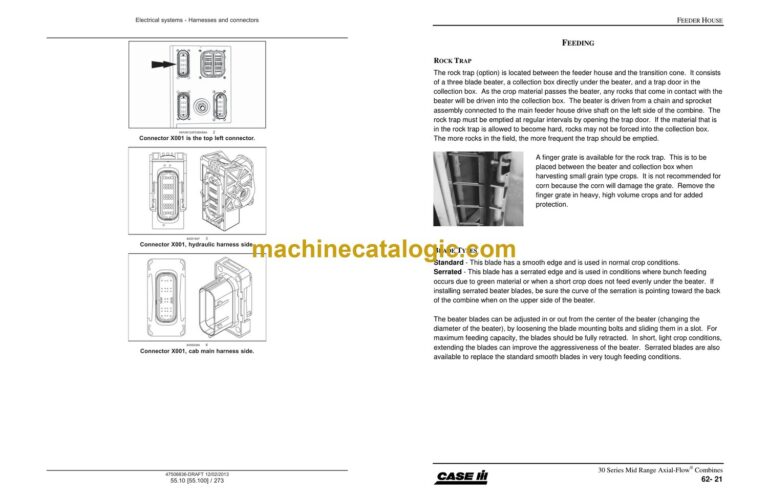
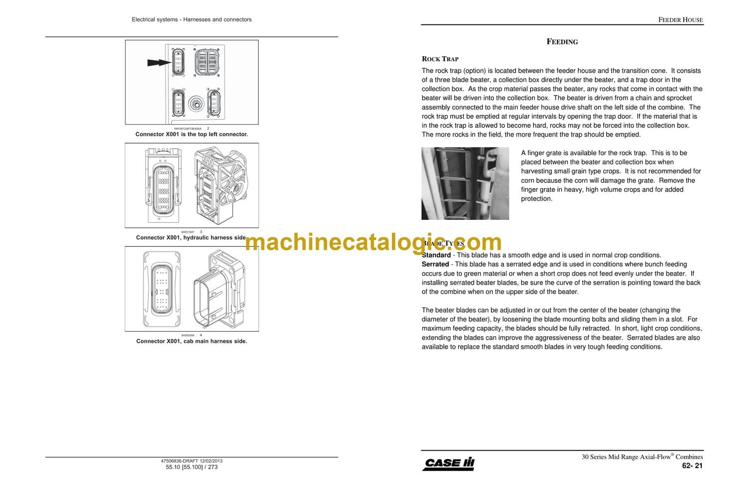
Rock Trap
Blade Types
Rock Trap
Drum Speed
Beater RPM
Driven
Driver
Feeder Problems
Operator Control Center
Multi-Function Handle
Right Hand Console
Cab Display
Global Machine Configured
Header Configurations
Screen: MAIN>TOOLBOX>HEAD 1
Header Configurations
Screen: MAIN>TOOLBOX>HEAD 1, con’t
Screen MAIN>TOOLBOX>HEAD 2
Run Screen Configurations
Navigate by: BACK>TOOLBOX>LAYOUT
MFH
MFH, con’t
RH Console Switches
RH Console Switches
1 – Calibrate: “Feeder Position”
2 – Calibrate: “Header tilt”
3 – Calibrate: “Ground Calibration”
Calibrate “Float Sensor”
UCM Memory Slots
Manually
Return to Cut
Return to Cut Over Ride
Modes Of Operation, con’t
Auto Height Control
Float Control
General:
How Do I Get Started, con’t
Setting the Operating Mode and Cutting Height:
The RESUME operation:
Modes Of Operation, con’t
Clearing The Set Points
Methods of Using the Set #1 or Set #2 Switches
Modes Of Operation, con’t
Methods of Using the Setting Switch
Lateral tilt (Terrain Tracker®)
General
Manual Operation (M)
Automatic Operation (A)
Clutch Belt Tensioning
Feeder Slip Clutch
Feeder Slip Clutch, con’t
Burnishing Feeder Clutch
Adjusting the Feeder Clutch
Feeder Slip Clutch, con’t
Reverser Operation
Normal Speed:
High Speed:
Electrical Components
Electrical Components, con’t
Reference Material
Key System Components
Power Supply Fuses
Grounds
Modes of Operations
Feeder Disengaged
Feeder Engaged
Modes of Operations, con’t
Feeder Drive Hydraulics
Feeder Disengaged Mode
Engaged
Reverser Drive Components
Reverser Drive Components, con’t
Reverser Gear Backlash Adjustments
Information Flow
Electrical Components
Reference Material
Power Supply Fuses
Grounds
Modes of Operations
Reverser Drive Hydraulics
Reverser Drive Hydraulics, con’t
Disengaged Mode
Engaged Mode
Header Recognition
Header Type, R-434
Reference
Key Components
General Information
Power Supply Fuses
Grounds
Modes of Operations
Header Recognition, R-434
Neutral, (NO Header Movement)
Modes of Operations, con’t
Neutral, (NO Header Movement), con’t
Modes of Operations, con’t
Header Raised/Lowered Manually
Modes of Operations, con’t
“Neutral”
Header Valve in Neutral
Accumulator
Ride Control Cartridge
Accumulator Charging
“Raise”
Header Raise
“Lower”
Header Lower
Feeder Valve Block
Out Side View
Bottom Side View, ( top view will mirror the bottom view)
Tilt Schematic
Neutral Position
Tilt “CW” Schematic
Right Tilt, CW
Cushion Valve
Left Tilt, CCW
Manual Mode
Automatic Speed Control
Configuring the Auto Reel Control
Reel Drive Types
Configuring the Auto Reel Control, Con’t
How do I Start
Reference Material:
Key Components:
Reel Mode Switch, ICP
Reel Speed Control, B-088
Reel Drive Electrical, con’t
Reel Speed AUTO Mode
Reel Speed Control
Feeder Valve Block
Out Side View
Neutral Operation
General Information
Neutral Operation
Reel Drive Hydraulics, con’t
Engaged Operation
Relief Valve Operation
System Configurations
Sensor Operation
Reference Material:
Key Components:
General Operation
Signal Valve Solenoid, Y-022F
Example
Reel Raise, “+”
Reel Fore/Aft Electrical
Reel Lower, Fore, Aft
Header Type Sensor
Reel Position Operation
Reel Raise/Lower Hydraulics
Neutral Position
Reel Raise
Reel Lower
Reel Fore/Aft Schematic
Reel Fore/Aft Neutral
Reel Fore
Reel AFT
_Sec 66 Threshing
Section 66 Threshing and Separation
Starting Pin: YDG009296
Table Of Contents
Crop Flow Through The Machine
Component Function
Feeding, (1)
Threshing, (2)
Separation, (3)
Threshing
Operation
How to Control Threshing
Threshing Chamber
Large Tube Rotor
Grain Type
Rasp Bar
Spike Raps Bar
Straight Bar
Kickers
Small Tube Rotor
Grain Type
Rasp Bar
Spike Raps Bar
Straight Bar
Kickers
Transition Cone
Transition Cone
Extended Wear
Rice
Feeding
Feeding
Rotor impeller wear
Threshing
Non-spiked rasp bar
Spiked Rasp Bar
Rasp Bar Mounting
Threshing
Rotor Attachments, con’t
10 Degree Spiked Rasp Bar
28 Degree Standard Rasp Bar.
Threshing
Straight Separator Bar – Large Tube Rotor
Straight Separator Bar – Small Tube Rotor
Helical Kicker Bar
Threshing
Repair
Small Wire
Large Wire
Slotted Concaves
Round Bar
Concaves
Concaves
Concaves
Concaves
Concave Hard Thresh Kit (Optional)
Concave Interrupter Bar (Optional)
Concave Filler Bars (Optional)
Concaves
Concaves
Concaves
Concaves
Concaves
Repositioning The Concave Pinch Point
Concaves
Crop Positing on the Auger Bed
Grates
Keystock or Bar
Slotted or Stamped
Solid
88 Series Combines
Separation
88 Series Machines
Rochelle Rotor
Crop Speed Control
Crop Speed Control
Beater
Straw Chopper
Guidelines For Optimizing Straw Quality
Recommended Combine Configurations
AFX Retimed Rotor
Other Equipment
Operating Conditions
Combine Settings
Machine Items to be Configured
Separator Drive Electrical
ON Road Switch, S-049
Seat Switch, S-73
Separator Switch, S-055
Rotor Speed Increase/Decrease Switch, ICP
Rotor Increase/Decrease Relays, RLY-334 & RLY-335
Rotor / Cover Select Relay, RLY-324
Rotor Speed Adjust Fuse, Inline 40 Amp.
Rotor Increase / Decrease Limit Switches, S-189A & S-189B
Rotor Speed Sensor, B-203
Engine Speed Sensor, ECU
Rear Ladder, B-247
Reference Material
Key System Components
Power Supply Fuses
Grounds
Modes of Operations
Separator Drive Electrical
Modes of Operations, con’t
Road Switch FIELD Mode
Seat Switch “CLOSED”
Rear Ladder Sensor
Separator Switch
Separator Drive Electrical
Modes of Operations, con’t
Instrumentation UCM
ASC Active:
ASC NOT Active:
Rotor Speed Electrical
Rotor Speed Switch, ICP
UCM
Rotor Speed Sensor, B-203
Rotor Speed Electrical
Rotor Speed Increase, con’t
Rotor Limit Switches, S-189A & S-189B
Rotor Decrease
Variable Rotor Speed Pulley (Driver)
Torque Sensing Pulley (Driven Pulley)
Torque Sensing Pulley (Driven Pulley)
Components Usage
Component
5088-5130
60-7088
61-7130
Cleaning Groove
Torque Sensing Pulley (Driven Pulley)
Service
Model
Step One
Step Two
Step Three
Step Four
Step Five
Rotor Belt Alignment
How to use the tool
A
B
C
Jackshaft Assembly Alignment
Rotor Drive Components
Jackshaft Assembly Alignment
Step 1 – Pulley Angle Adjustment
Jackshaft Assembly Alignment
Step 2 – Pulley Alignment
Variable Rotor Speed Pulley Limit Switches
Step 3 – High Speed Limit Switch Adjustment (Front), S-189A
Variable Rotor Speed Pulley Limit Switches
Step 4 – Low Speed Limit Switch Adjustment (Rear), S-189B
Driven Pulley Adjustment
Step 5 – Adjusting Torque Sensing Pulley
Regulated Control Valve
Concave Position Electrical
Electrical Components
Concave Switch, ICP
Concave Relays, K-21 & K-24
Concave Motor, M-222
Concave Position Sensor, B-223
Key System Components
Power Supply Fuses
Grounds
Concave Stationary
Concave Switch
Concave Position Sensor
Concave Position Electrical
Modes of Operations, con’t
Concave Switch
UCM
Identifying Harvest Loss
Identifying Harvest Loss
Identifying Harvest Loss
Notes
Word Bookmarks
_Sec 67 Cleaning Residue
Section 67 Cleaning & Residue
Starting Pin: YDG009296
Table Of Contents
Auger Bed, (1)
Straw Chopper, (2)
Chaffer (Upper) Sieve, (3)
Cleaning
Shoe (Lower) Sieve, (4)
Tailings Auger, (5)
Clean Grain Auger, (6)
Cleaning
Cleaning Fan, (7)
Cleaning
Operation
How to Clean the Grain
Auger Bed Operation
Auger Bed
Auger Paddle, (3)
Auger Bed Operation
Grain Pan
Chaffer Fingers
Auger Bed Operation
Cleaning Fan
Cleaning System
General Fan Characteristics
Cleaning System
Cleaning System Adjustments With Cross Flow Fan
Chaffer Sieve Design
Sieve Operation
Sieve Operation
Air
Sieve Opening
Sieve Operation
Air Blast
Sieve Opening
Sieve Examples
1-1/8” Grain Slat
1-1/8” closz Slat
Sieve Reference Page
Sieve Examples
1-5/8” Closz Slat
1-5/8” Corn Slat
Sieve Reference Page
Sieve Examples
1-1/8” Peterson Sieve
Fixed Hole Lower Sieve
Sieve Reference Page
Sieve Examples
Sieve Adjustment
Setting Tool
Spreader Driven Pulley
Spreader Bats
Curved Bats
Circuit Components
Chaff Spreader Speed Sensor, B-291
Chaff Spreader Position Sensor, B-293
Reference Material
Key System Components
Power Supply Fuses
Grounds
Modes of Operations
Chaff Spreader Drive Electrical
Modes of Operations, con’t
Position Sensor, B-293
Position Sensor, B-293
Spreader Solenoid, Y-294
Spreader Speed Sensor, B-123
Chaff Spreading Hydraulics
Chaff Spreading Hydraulics
Control Valve Operation
Reference Material:
Key Components:
Chaff Spreading Hydraulics
Control Valve Operation
Operator Control Center
Right Hand Console
Right Rear Side of Machine
Auto Crop Settings
Machine Configuration
Global Machine Configuration
Machine Configuration
ON Road Switch, S-049
Upper Sieve Increase/Decrease Switch, ICP
Lower Sieve Increase/Decrease Switch, ICP
Remote Upper Sieve Increase/Decrease Switch, S-238
Remote Lower Sieve Increase/Decrease Switch, S-237
Upper Sieve Actuator & Position Sensor, M-275
Lower Sieve Actuator & Position Sensor, M-274
Calibrate: “UPPER Sieve”
Sieve Components
Upper Sieve Switch, ICP
Remote Upper Sieve Switch, S-238
Lower Sieve Switch, ICP
Remote Lower Sieve Switch, S-237
Road Mode Switch, SW-038
Diode Module, V-077
Sieve Components
Electrical Components, con’t
Upper Sieve Position, M-275
Upper Sieve Position, M-274
Reference:
Power
Ground
Sieve Operation Electrical
Upper Sieve Adjustments, Right Hand Consol, con’t
INCREASE, (In Cab): – Engine Running and all Controllers power
Switch
UCM
Actuator
Monitoring
Sieve Operation Electrical
INCREASE, (Remote): – Key Switch OFF Position
Remote Switch
General Information
Cab Display
Indicators
Sieve Sensors, (Example Right Side)
Cab Display
Cab Display
Tailing Volume Sensor
Tailings Sensor
Word Bookmarks
_Sec 80 – Automatic crop setting
_Sec 91 3020 Header with ops manual
Flex Header Valve
Header Leveling
Feeder Face Angle Adjustment
General Information
Reference Material
Key System Components
Decreasing Cutter Bar Weight, (Making the cuter bar Lighter)
MFH & UCM
The UCM will control the following functions:
Signal valve
Reel FORE Valve
Swap Relays
Suspension Sensor
Increasing Cutter Bar Weight, (Making the cuter bar Heavier)
MFH & UCM
The UCM will control the following functions:
Signal valve
Reel FORE Valve
Swap Relays
Suspension Sensor
Suspension “Neutral”
Control Valve Operation
Reference Material:
Key Components:
Suspension & Reel Fore/Aft – “Neutral”
Suspension Pressure – “Decreasing Ground Pressure”
The following pages are from the 3020 Assist Concert KM1464105.
3020 Grain Head – Additional Set-up Instructions
Cutterbar Inspection
Cutterbar Inspection, con’t
Cutterbar Inspection, con’t
Correcting Cutterbar and A-frame Position
Correcting Cutterbar and A-frame Position, con’t
Correcting Cutterbar and A-frame Position, con’t
Correcting Cutterbar and A-frame Position, con’t
Correcting Cutterbar and A-frame Position, con’t
Correcting Cutterbar and A-frame Position, con’t
Cutterbar Support Arm Limit Link Hardware
The following pages are from the 3020 operators manual
form number 84557591.