Case AFX Series Axial-Flow Combine Index:
Binder Cover book one 3-06
Sec 2 Sales Guide 1-18 low Res
Sec 01 Intro 3-7-06
Sec 11 Engine 3-06
Sec 25 Trans Final Drives 3-06
Sec 29 Hydrostatic Drive 01_05
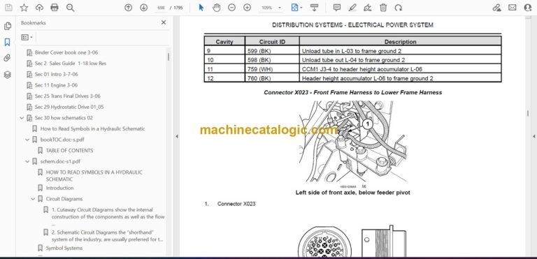
Sec 30 how schematics 02
How to Read Symbols in a Hydraulic Schematic
bookTOC.doc-s.pdf
schem.doc-s1.pdf
schem.doc-s2.pdf
Sec 35 General Hydarulic 3-06
Purpose Of The Training Manual
Use Of This Manual
Flow Across a Restriction
Pilot Operated Hydraulic System
Hydraulics
Control Pressure
Hydraulics
Control Pressure
Component
Specification
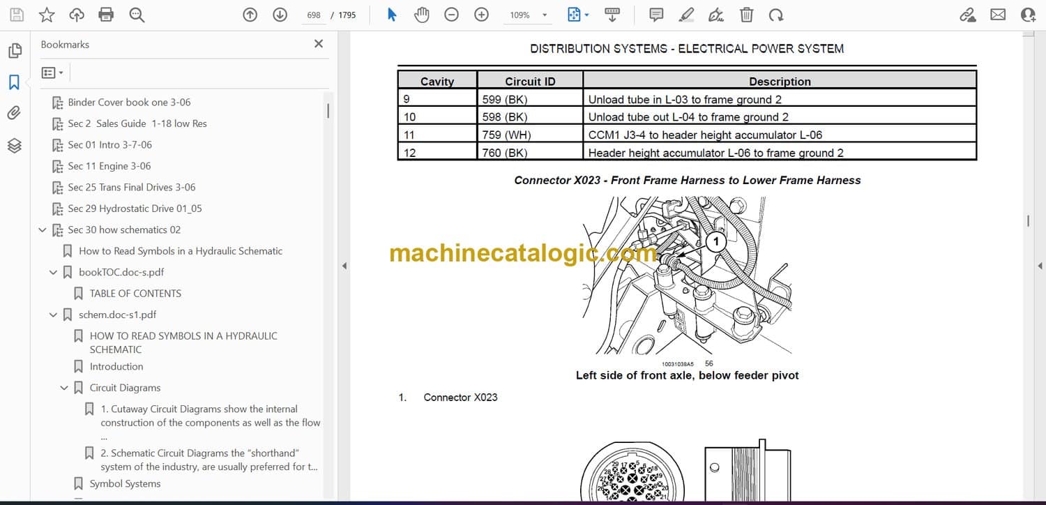
Hydraulic Component Locations
Oil Supply
Filtration
Cooling
Cooling
Gear Pumps
Hydraulic Schematic
Hydraulic Schematic
PFC Component Locations
PFC Piston Pump
PFC Pump Schematic
PFC Piston Pump
PFC Pump Operation
Pump Compensator
Low Pressure Standby
Low Pressure Standby
Pressure and Flow Compensation
Pressure and Flow Compensation
High Pressure Standby
High Pressure Standby
Main Machine Stack Valve
Steering Priority Valve
Steering Priority Valve
Steering Hand Pump
Steering Neutral
Power Turn (left or right)
Manual Steering
Manual Turn (left or right)
Electrical Monitoring Circuits
Hydraulic Filter Restrictions Switch
Hydraulic Oil Temperature Sensor
Electrical Monitoring Circuits
Reservoir Tank Level Switch
Park Brake / Regulated Pressure Valve
Park Brake / Regulated Pressure Valve
Component Location
Regulated Pressure Schematic
Regulated Pressure Valve Operation
Electrical Monitoring Circuits
Park Brake Pressure Sensor
Control Pressure Pump
Filtration
Control / Lubrication Pressure Valve
Control Pressure Schematic
Control Pressure Schematic
Electrical Monitoring Circuits
Control Pressure Filter Restrictions Switch
Control Pressure Sensor
Cooling
Electrical Monitoring Circuits
Ground Drive Motor Temperature Sensor, (case drain)
Lubrication Pressure Sensor, (PTO Gearbox)
Test Procedure
Test Procedure
Test Procedure
Pressurizing the valve from the side.
Pressurizing the valve from the end.
Test Procedure
Terrain Tracker Relief Valve
Spreader Relief Valve
Fan Drive Relief Valve
Feeder Lift Cylinder Thermal Relief Valve
Test Procedure
Test Procedure
Test Procedure
Test Procedure
If Flow Is Below Specifications
Test Procedure
If Flow Is Below Specifications
Test Procedure
Test Procedure
If Flow Is Below Specifications
Testing Information
Test Results:
Testing Information
Test Results:
Baseline control pressure flow
DEALING WITH RESULTS
Baseline control pressure flow
PTO and CVT clutch flow
• Feeder ETR Clutch
Ground drive, Rotor and Feeder Hydrostatic flow
Fluctuations in control pressure and hydraulic squeal after
Sec 39 Schematics Fold Out 3-06
Sec 41 Atlas
CNH Engine Diagnostic Tool
1 CNH — Engine Diagnostic Tool
Electronic Service Tool – All Appropriate Products
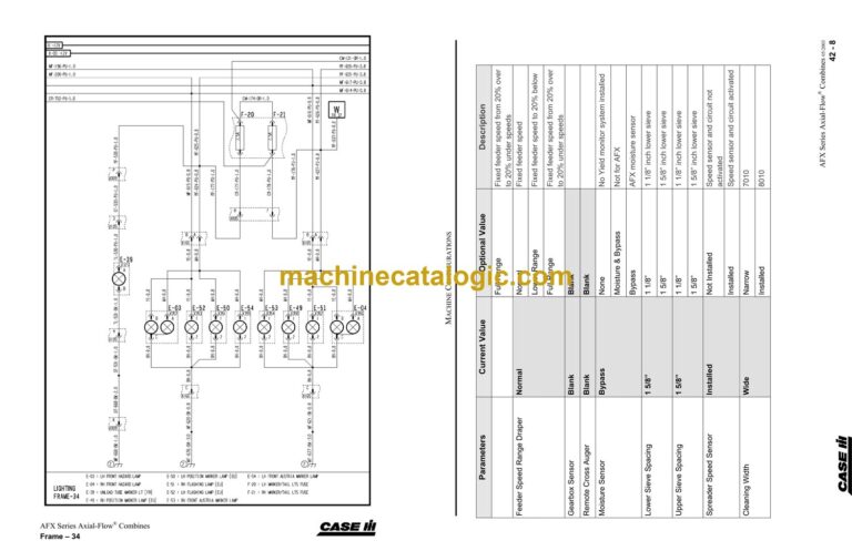
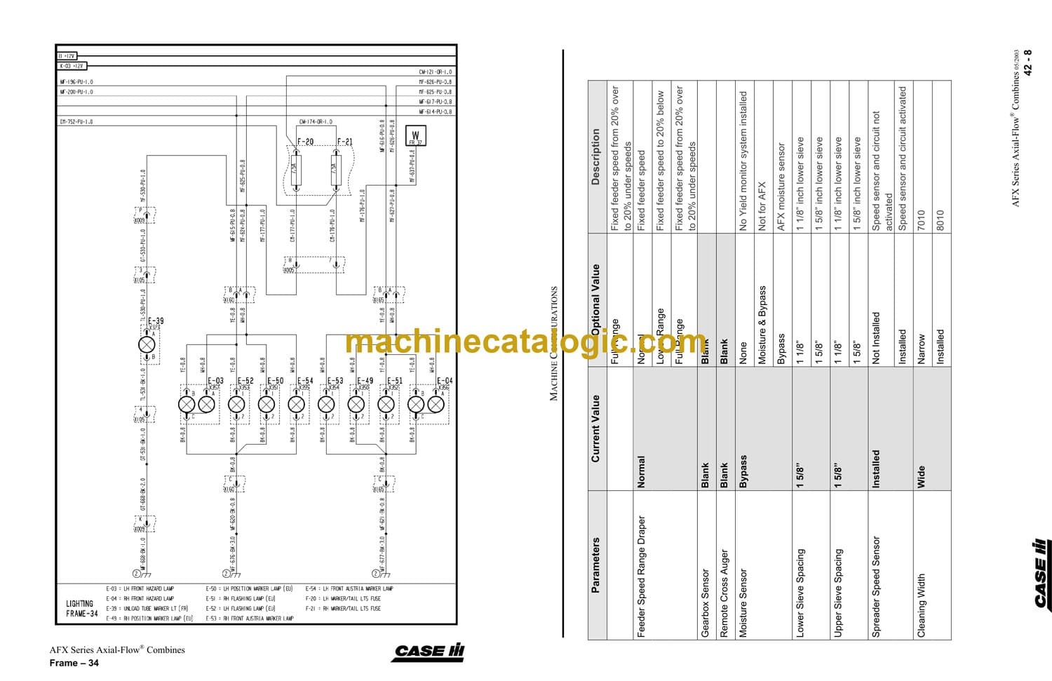
Sec 42 Configurations 01_05
Sec 50 How To Read Schematics 03_06
test cover.pdf
Sec 51 Connector Guide 03_06
Sec 53A Electrical Schematic 10-04
Sec 53B Electrical Schematic 01_05
Sec 53C Electrical 3-06
Sec 55 Electrical Circuits 3-06
Sec 56B MY06 How to use Diag Master
Diagnostic Screens
History Screens
Controller Status Screen
Memory Card Screen
Active Error Code
History Screen Operation Introduction
DIAG>HISTORY Screen
HISTORY Screens
Fault Screen
Alarm Screen
Error Screen
Diagnostic Screen Introduction
DIAG Screen
Sub System
Sub System Pick List, Example picking “HEADER”
Sensor
Sensor Pick List Example: Header>Reel Raise SW
DIAG Screen Examples
Parameter
Parameter Scroll Bar List Examples:
Diagnostic Input Screens
VOLTAGE
Proximity and Speed Sensors
Temperature/Fuel Level Senders
Diagnostic Input Screens
VOLTAGE, con’t
Potentiometers/Pressure Senders/Grain Bin Level
Diagnostic Input Screens
Switches
Relative Position
GEAR
Other Parameter items
Sensor Abbreviations
Sensor Abbreviations cont’d.
Diagnostic Outputs
Diagnostic Outputs – PWM Output
Diagnostic Outputs – H Bridge Output
Diagnostic Outputs – ON/OFF Output
Controller Information
ICDU
CCM’s, RHM, SSM
YMIU
GPS
Data Card Information
Sec 57 Fault Codes 10_04
Section Lay Out
Fault Codes
Component Listing
Diagnostic Description
SPN
Controller
FMI#
FMI
FMI#
FMI
CCM1
CCM 2 Listing
CCM3 Listing
RHM Listing
Engine Controller
Power Reduction Errors
For Iveco engines:
Clearing passive errors from engine ECU
System
(SORT)
Function
(PARAMETER)
Component
What Is Being Checked
(MEASUREMENT)
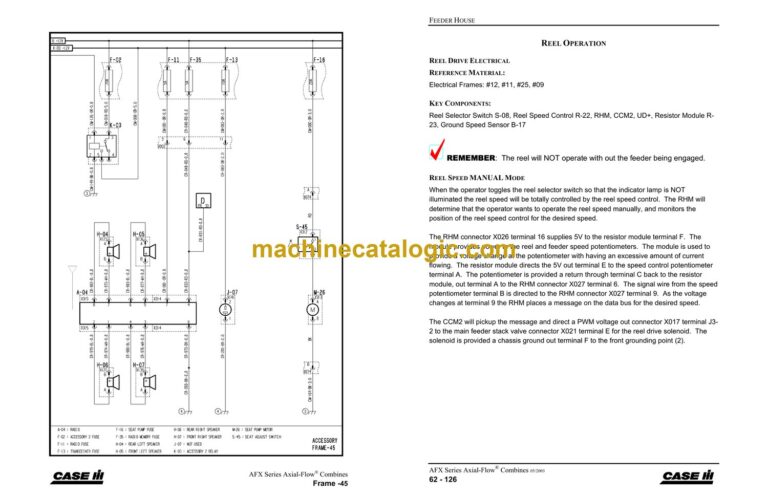
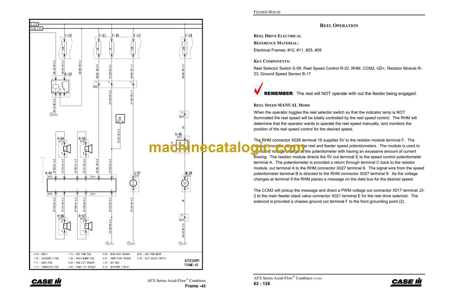
Sec 62 Feeder Drive 01_05
Sec 62 Feeder Power Flow 10_04
Sec 63 Fixed Speed Feeder MY05
Sec 66 Threshing & Separating 3_06
Sec 66 Rotor Power Flow 10_04
Sec 67 Cleaning & Residue 01_05
Sec 74 Unloading 10_04
Acronyms and Abbreviations
Specifications
Mechanical Specifications
Hydraulic Specifications
Electrical Specifications
Introduction
Grain Tank Cover Operation, (Euro Only)
OPEN
CLOSE
Unloading System Operation
Grain Tank Level Sensors
Unloading Auger Swing
Unloading Auger Engagement
Auger Slow Down Kit
Operator’s Controls
Circuit Sensors
Systems Mechanical Power Flow
Electrical Controls
Grain Tank Covers
Reference Material
Operation
Grain Tank “Full” Sensor
Grain Tank Level Sensors
Reference Material
Operation
Hydraulic Components
Main Valve
Auger Swing Valve
Hydraulic Schematic
Reference Material:
Operation
Auger Swing Cylinder
Cylinder and Load Checks
Auger Swing Cylinder
Cylinder Schematic
Hydraulic – Auger Cylinder Operations
Reference Material:
Auger Swing Valve in Neutral
Auger Swing Cylinder Extending (OUT)
Hydraulic – Auger Cylinder Operations, con’t
Electrical Flow Chart
Multi-Function Handle
Electrical – Auger Swing Operation
Reference Material:
Swing Out
Swing IN
Unloading Auger Clutch
PTO Gearbox Facing Out
Unloading Auger Clutch
Unloading Auger Valve
Hydraulic Schematic
Hydraulic – Control Valve Operations
Reference Material:
Operation
Electrical – Auger Clutch Operation
Reference Material:
Unloading Clutch Engaged
Trouble Shooting
Sec 81 AFS AFX MY06
Grain Flow Sensor
Clean Grain Elevator RPM Sensor
Moisture and Temperature Sensor
Moisture and Temperature Bypass Unit
Moisture and Temperature Bypass Unit
How it works
Moisture and Temperature Bypass Unit
Ground Speed Sensor
Feeder Position Sensor
Yield Monitor Interface Unit, “YMIU”
Yield Monitor Interface Unit, “YMIU”
Display Unit (ICDU)
ICDU2 (one card slot)
Data Card
Data Card
Card Information
Data Card
Card Information
Data Card
Card Management
Electrical System Lay-Out
CAN Bus
CAN Terminators
Electronic Service Tool Interface Connector
GPS (Global Positioning System) Receivers
GPS (Global Positioning System) Receivers
Attaching non factory GPS Receivers
AFS Desktop Software
AFS Desktop Software
AFS Desktop Software
AFS Harvesting Information Data Flow
AFS Harvesting Compatibility Chart
The Status and Warning Indicators
Is the system RECORDING data?
Do the Values seem realistic?
The Yield Equations
Dry Bushels
Are the Sensors working?
Are the Sensors working?
Are the Sensors working?
Are the Sensors working?
Are the Sensors working?
Are the Sensors working?
Is GPS Working?
Is GPS Working?
Is GPS Working?
Setup and Calibration
Setup and Calibration
Setup and Calibration
Setup and Calibration
Setup and Calibration
The RUN screens
Is the system RECORDING data?
Do the Values seem realistic?
The Yield Equations
Dry Bushels
Are the Sensors working?
Are the Sensors working?
Are the Sensors working?
Are the Sensors working?
Are the Sensors working?
Are the Sensors working?
Is GPS Working?
Is GPS Working?
Setup and Calibration
Setup and Calibration
Setup and Calibration
Setup and Calibration
Setup and Calibration

