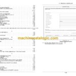
CNH Electronic Service Tool EST, Remote Service Tool RST Index:
INTRODUCTION
General information
Shortcut icons
Start the Electronic Service Tool (EST) base software
User interface overview
Status: controller, hardware, software, and communication
Menu bar
Electronic Service Tool (EST) software version
Adjusting and sorting columns
RECOMMENDATIONS AND BEST PRACTICES
Recommendations and best practices
SOFTWARE INSTALLATION AND SETUP
Requirements for installing the EST base software
Obtain the Electronic Service Tool (EST) software
Install the EST on a new computer the first time
Install or update the EST on an already programmed computer
Install machine controller files from the Dealer Portal
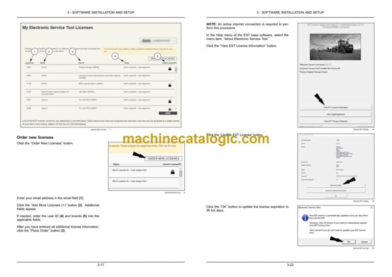
Electronic Service Tool (EST) license management
Electronic Service Tool (EST) update tool
INSTALLING UPDATED HARDWARE ADAPTERS
Communication adapters
Electronic Service Tool (EST) Dearborn Protocol Adapter 5 (DPA 5) firmware installation
RS-232 serial adapter
ELECTRONIC SERVICE TOOL (EST) COMPONENTS
Electronic Service Tool (EST) kit components
Universal Serial Bus (USB) port connections
Benchtop programming harness 380002901
Desktop harness kit
PTO and hitch software download kit
Power options
ELECTRONIC SERVICE TOOL (EST) MAINTENANCE
Electronic Service Tool (EST) carry case (North America only)
Prepare the Electronic Service Tool (EST) computer for transport
Damage requiring service
CONNECTIONS, STARTING, AND STOPPING
Computer power supply
Serial communication – Electronic Service Tool (EST) computer connection
Universal Serial Bus (USB) port connections
Diagnostic Cables and Adapters
Basic Vehicle Connections
Connecting to the Controller Area Network (CAN) or Controller
Electronic Service Tool (EST) computer connections
Connect the Electronic Service Tool (EST) computer directly to the controller
BENCHTOP HARNESS
Introduction
Benchtop programming components
Benchtop harness power supply
Connect the diagnostic connector
Setup for programming
Requirements for programming
Program a flow monitor or flow gateway
Program a display using a USB flash drive
ELECTRONIC SERVICE TOOL (EST) TROUBLESHOOTING
Troubleshoot Electronic Service Tool (EST) base software communication issues
Communication status “Off Line”
Comm link status (communication status)
Controller communication – establishing communication with the controller(s)
Protocol adapter
Communication (COM) port settings
Adapter cable illustrations and pinouts
MACHINE DIAGNOSTICS WITH THE ELECTRONIC SERVICE TOOL (EST)
Controller Area Network (CAN) system troubleshooting
Equipment selection
Diagnostic connector selection
“Vehicle Connector Selection” screen
“Selected Connector Not Supported” message
“Controller Status” screen
Communication status – “On Line”
Communication status – “Off Line”
One or more controllers are “Off Line”
Controller connectors
Controller power supply and ground
Test Controller Area Network (CAN) data bus continuity and voltage
Program mode
Controller Area Network (CAN) logging
ETIM GO AND LEGACY DIAGNOSTICS
Install eTIM GO
Configure eTIM options
eTIM GO
Download eTIM GO system updates and series data
The Legacy Diagnostics tool
Install the Legacy Diagnostics tool
Using the Legacy Diagnostics tool
VIEWING VERSIONS, FAULTS, AND LOG FILES
Electronic Service Tool (EST) base software controller version, and fault code files
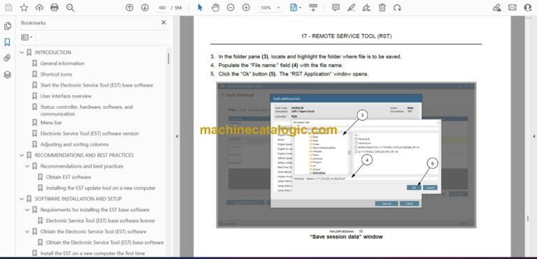
Save a fault code file
Open a fault file using the Electronic Service Tool (EST) base software
Open a fault file using Notepad
Save a controller version file
Open a controller version file using the Electronic Service Tool (EST) base software
Open a Controller Version File using Notepad
PARAMETER LOGGING
General information
Setup
“Change View Parameters” window
Managing parameter templates
Log parameters
Log Parameter Settings
Status: Logging
Marking the log file
Stopping the logging session
Saving the log file
Exit
Open a parameter log file
PROGRAM A CONTROLLER
Controller programming
Program a controller
Program a new display from Parts
Program a display with a software update using a USB device loaded from the EST
Software bundles – Unlock an Over the Air (OTA) update of a display and module
Vehicle speed registration
Register vehicle speed
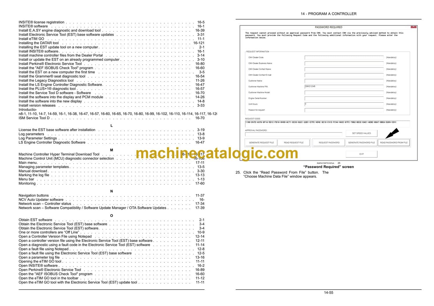
Engine programming approval passwords
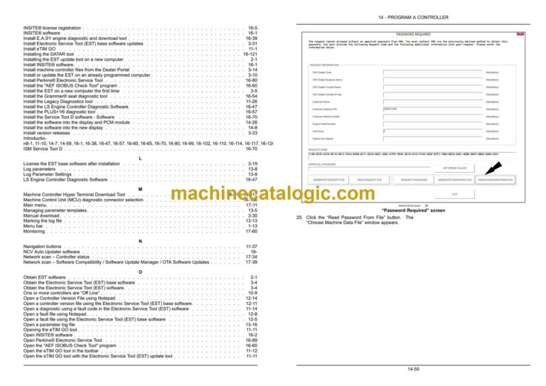
Use an approval password for engine programming
CONFIGURATION
Vehicle configurations
Unlock a feature
Configure the Vehicle Identification Number
ELECTRONIC SERVICE TOOL (EST) ADDITIONAL TOOLS
INSITE® software
E.A.SY tool
LS Engine Controller Diagnostic Software
Grammer® seat diagnostic tool
PLUS+1® diagnostic tool
NO TITLE
AEF ISOBUS Check Tool program
EEPROM Dumper Tool
ISM Service Tool D
Perkins® Electronic Service Tool
Excavator Handy Checker tool
Download and diagnostic tools for the wheel loader model 1221E
Transmission diagnostic tool for road graders
Automatic Slip Control (ASC) tool
Machine Controller Hyper Terminal Download Tool
DATAR scope and diagnostics
Introduction
Install INSITE® software
Open INSITE® software
INSITE® license registration
Register the INSITE® license
Configure the communication adapter for INSITE®
Download and install INSITE® software calibrations
Program an engine controller with INSITE®
Introduction
Install E.A.SY engine diagnostic and download tool
Selecting E.A.SY engine diagnostic and download tool
Start the E.A.SY engine diagnostic and download tool
E.A.SY engine diagnostic and download tool main screen
E.A.SY Engine Diagnostic and Download Tool – Quick Start Screen
Introduction
Install the LS Engine Controller Diagnostic Software
Register the LS Engine Controller Diagnostic Software license
Open the LS Engine Controller Diagnostic Software
Overview
Install the Grammer® seat diagnostic tool
Introduction
Install the PLUS+1® diagnostic tool
Open the PLUS+1® diagnostic tool
Introduction
Install the “AEF ISOBUS Check Tool” program
Open the “AEF ISOBUS Check Tool” program
Introduction
Take an EEPROM download from a controller
Upload an EEPROM file to a controller
Introduction
Install the Service Tool D software – Software
Electrical system – Install – Communication adapter
Introduction
Install Perkins® Electronic Service Tool
Register the Perkins® Electronic Service Tool license
Perkins® Electronic Service Tool licensing fault codes
Open Perkins® Electronic Service Tool
Configure the communication adapter
Program a controller – New Engine Control Module (ECM)
Use an approval password for engine programming
Program a controller – Existing Engine Control Unit (ECU)
Introduction
Select the Handy Checker tool
Introduction
Selecting wheel loader
Diagnostic connector selection
Cluster download tool
Engine diagnostic connector selection
“Engine Diagnostic Tool – QSM11”
Machine Control Unit (MCU) diagnostic connector selection
Open the Machine Control Unit (MCU) download tool
Introduction
Selecting the road grader
Diagnostic connector selection
Transmission diagnostic tool
Introduction
Selecting compaction roller
Automatic Slip Control (ASC) tool
Introduction
Selecting the CX-series excavator
Machine Controller Hyper Terminal Download Tool
Introduction
Installing the DATAR tool
DATAR Scope
Selecting the DATAR tool
DATAR scope screen
Selecting a test
DATAR tool diagnostics
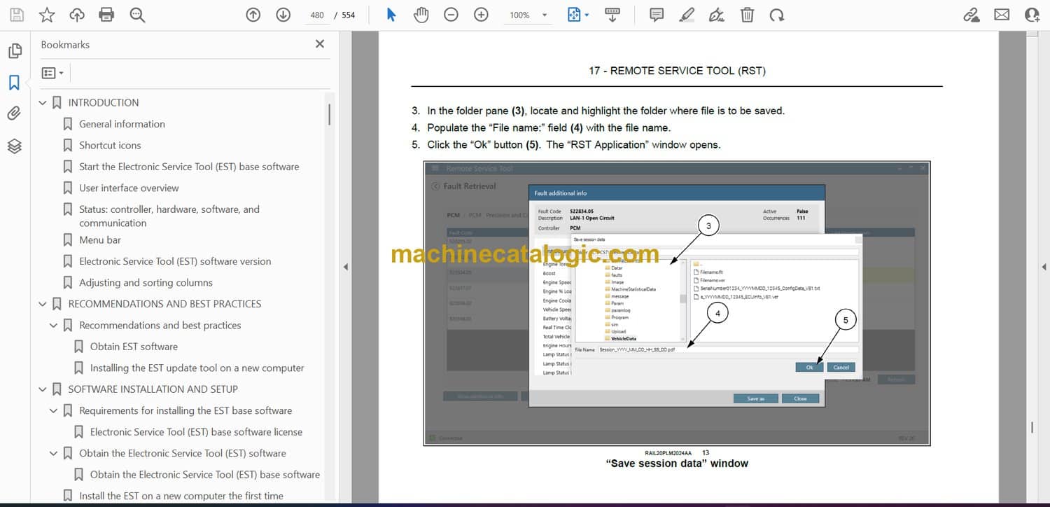
REMOTE SERVICE TOOL (RST)
Introduction
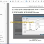
Connections, starting and stopping the Remote Service Tool (RST)
Remote Service Tool (RST) error codes
Available functions
Main menu
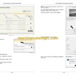
Network scan – Controller status
Network scan – Software Compatibility / Software Update Manager / OTA Software Updates
Faults
Monitoring
eTIM Manual
Programming
Configuration
Flight recorder reading
Custom functions
Telematics unit update
CAN recorder
Data Implements
Remote Display View