Format: PDF (Printable Document)
File Language: English
File Pages: 323
File Size: 32.92 MB (Speed Download Link)
Brand: Sumitomo
Model: SH135X-3B Hydraulic Excavator
Book No: MST-15-00-003EN
Type of Document: Service Text
$ 45
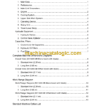
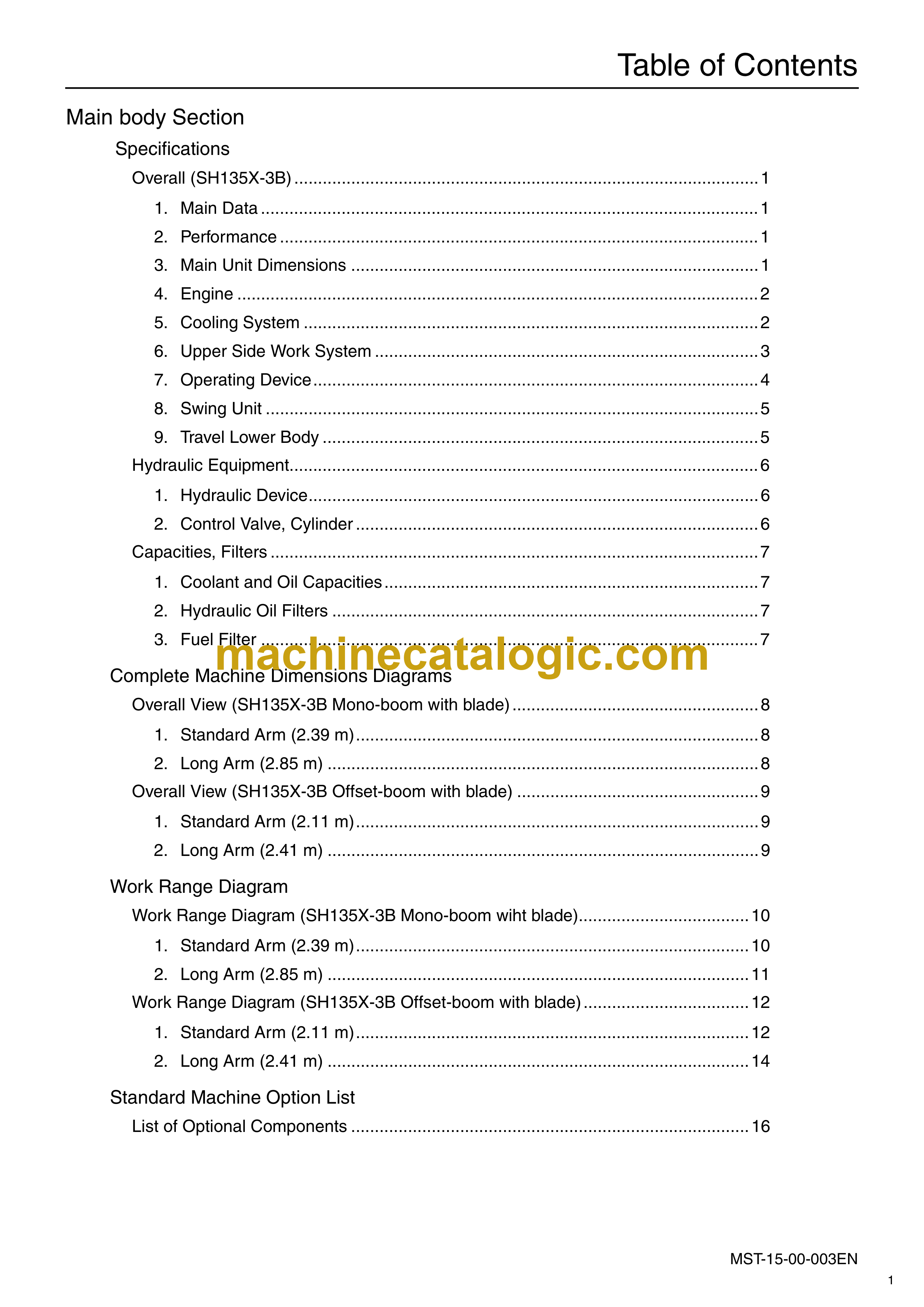
Main body Section
Specifications
Overall (SH135X-3B) ……………………………………………………………………………………..1
1. Main Data ……………………………………………………………………………………………1
2. Performance ………………………………………………………………………………………..1
3. Main Unit Dimensions …………………………………………………………………………..1
4. Engine ………………………………………………………………………………………………..2
5. Cooling System ……………………………………………………………………………………2
6. Upper Side Work System ………………………………………………………………………3
7. Operating Device………………………………………………………………………………….4
8. Swing Unit …………………………………………………………………………………………..5
9. Travel Lower Body ………………………………………………………………………………..5
Hydraulic Equipment………………………………………………………………………………………6
1. Hydraulic Device…………………………………………………………………………………..6
2. Control Valve, Cylinder ………………………………………………………………………….6
Capacities, Filters ………………………………………………………………………………………….7
1. Coolant and Oil Capacities …………………………………………………………………….7
2. Hydraulic Oil Filters ………………………………………………………………………………7
3. Fuel Filter ……………………………………………………………………………………………7
Complete Machine Dimensions Diagrams
Overall View (SH135X-3B Mono-boom with blade) …………………………………………….8
1. Standard Arm (2.39 m)………………………………………………………………………….8
2. Long Arm (2.85 m) ……………………………………………………………………………….8
Overall View (SH135X-3B Offset-boom with blade) ……………………………………………9
1. Standard Arm (2.11 m)………………………………………………………………………….9
2. Long Arm (2.41 m) ……………………………………………………………………………….9
Work Range Diagram
Work Range Diagram (SH135X-3B Mono-boom wiht blade)………………………………10
1. Standard Arm (2.39 m)………………………………………………………………………..10
2. Long Arm (2.85 m) ……………………………………………………………………………..11
Work Range Diagram (SH135X-3B Offset-boom with blade)……………………………..12
1. Standard Arm (2.11 m)………………………………………………………………………..12
2. Long Arm (2.41 m) ……………………………………………………………………………..14
Standard Machine Option List
List of Optional Components …………………………………………………………………………16
Overall View
Equipment Layout………………………………………………………………………………………..17
Overall……………………………………………………………………………………………………17
Operator’s Seat ……………………………………………………………………………………….18
Main Equipment Table
Lower Assembly Diagram (overall) …………………………………………………………………19
1. SH135X-3B (mono-boom with blade/offset-boom with blade)……………………19
Lower Component ……………………………………………………………………………………….20
1. Travel Unit………………………………………………………………………………………….20
2. Take-up Roller ……………………………………………………………………………………20
3. Upper Roller ………………………………………………………………………………………20
4. Lower Roller ………………………………………………………………………………………20
5. Recoil Spring……………………………………………………………………………………..21
6. Shoe …………………………………………………………………………………………………21
Upper Component ……………………………………………………………………………………….22
1. Swing Unit …………………………………………………………………………………………22
Engine-related …………………………………………………………………………………………….23
1. Engine ………………………………………………………………………………………………23
2. Muffler ………………………………………………………………………………………………24
3. Air Cleaner (double element)………………………………………………………………..24
4. Radiator…………………………………………………………………………………………….24
5. Fuel Tank…………………………………………………………………………………………..25
6. Hydraulic Oil Tank……………………………………………………………………………….27
Hydraulic Device………………………………………………………………………………………….29
1. Hydraulic Pump ………………………………………………………………………………….29
Control-related…………………………………………………………………………………………….30
1. Control Valve ……………………………………………………………………………………..30
2. Solenoid Valve (3 stack) ………………………………………………………………………31
3. Remote Control Valve………………………………………………………………………….32
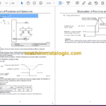
4. Remote Control Valve Characteristic Diagram………………………………………..34
5. Cushion Valve (with heat circuit) …………………………………………………………..36
6. Center Joint ……………………………………………………………………………………….36
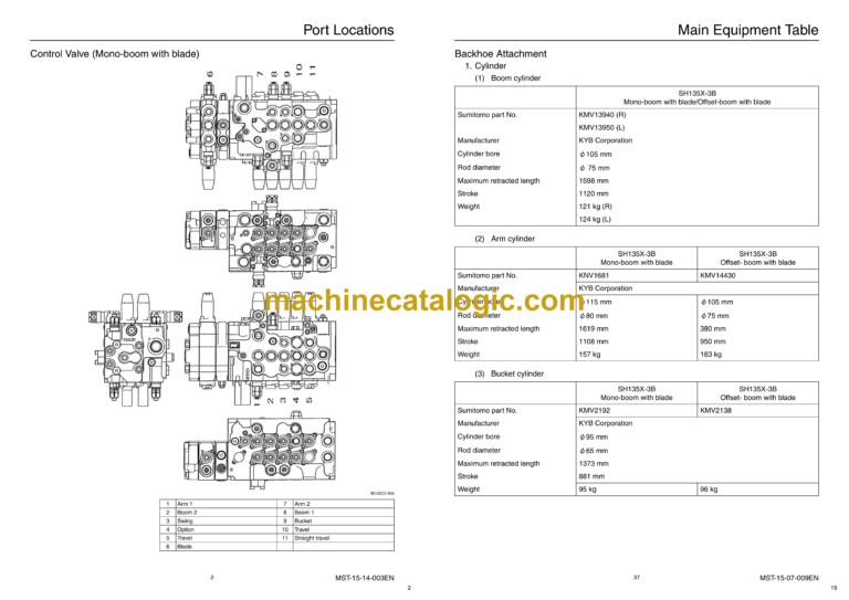
Backhoe Attachment…………………………………………………………………………………….37
1. Cylinder …………………………………………………………………………………………….37
2. Attachments ………………………………………………………………………………………39
Hydraulic Section
Hydraulic Pump
Structure and Operation Principles…………………………………………………………………..1
1. Pump Breakdown Diagram…………………………………………………………………….2
2. Pump Assembly Cross-Section Diagram …………………………………………………3
Control Valve
Operation……………………………………………………………………………………………………..5
1. When All Spools in Neutral…………………………………………………………………….5
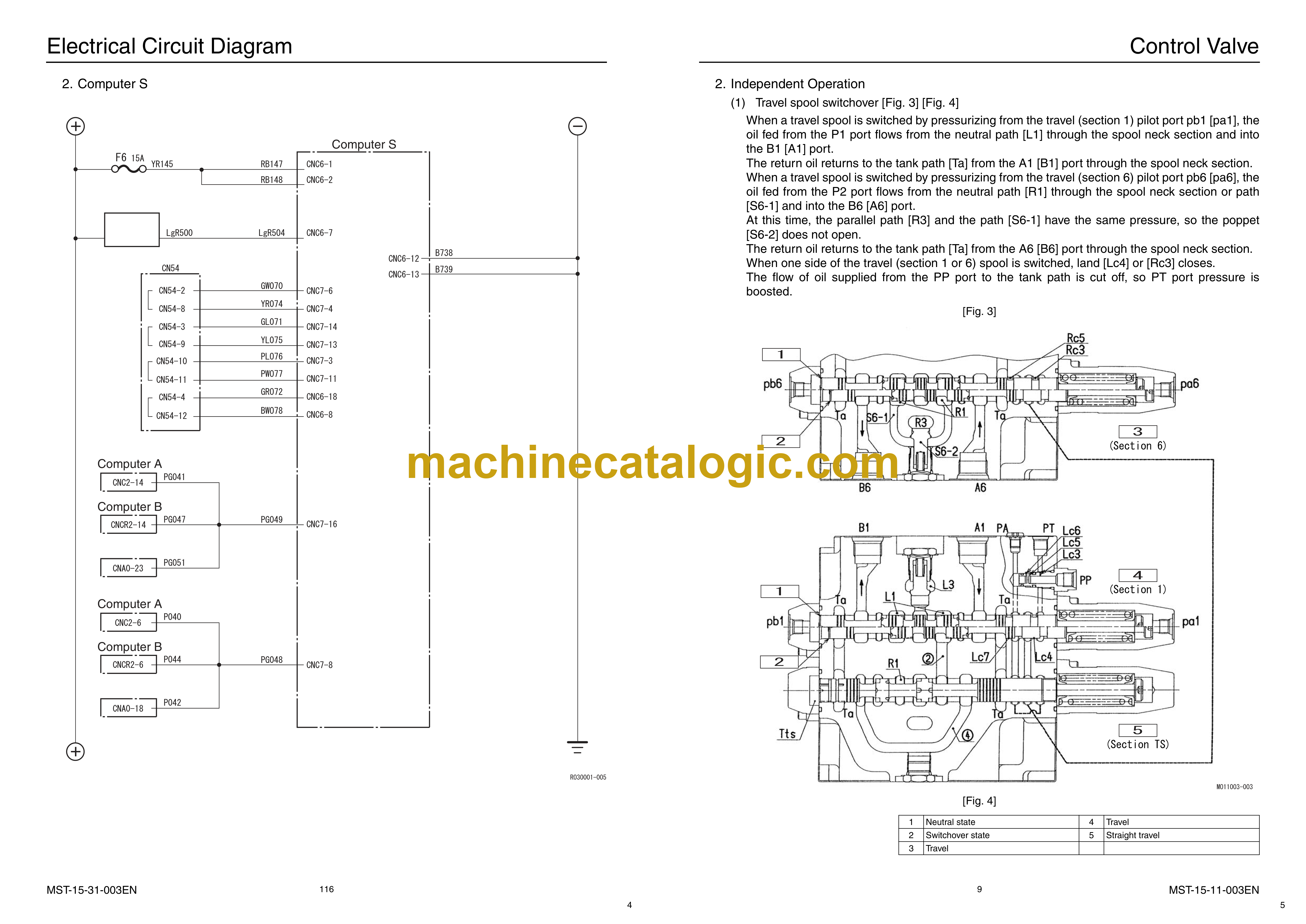
2. Independent Operation………………………………………………………………………….9
3. Compound Operation ………………………………………………………………………….21
Swing Unit
Swing Motor………………………………………………………………………………………………..24
Mechanical Brake ………………………………………………………………………………………..25
Make-up Valve …………………………………………………………………………………………….26
Swing Relief Valve ……………………………………………………………………………………….27
1. Operation Explanation for When the Relief Valve is Pressurized……………….27
Reverse Prevention Valve……………………………………………………………………………..29
Swing Reduction Gear………………………………………………………………………………….30
Trouble and Countermeasures ………………………………………………………………………31
Assembly Cross-section Diagram…………………………………………………………………..32
Main Equipment Structure and Operation Explanation
Motor …………………………………………………………………………………………………………34
1. Travel Motor ……………………………………………………………………………………….34
Hydraulic Circuit Section
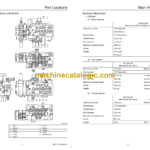
Port Locations
Hydraulic Pump
(Mono-boom with blade/Offset-boom with blade) …………………………………..1
Control Valve (Mono-boom with blade)……………………………………………………………..2
Control Valve (Offset-boom with blade) …………………………………………………………….4
Pilot Hose Connection Diagram
Pilot P and T Lines (Mono-boom with blade)……………………………………………………..6
Pilot P and T Lines (Offset-boom with blade) …………………………………………………….8
Pilot Control Line (Mono-boom with blade)………………………………………………………10
Pilot Control Line (Offset-boom with blade) ……………………………………………………..12
Function List
Function Table …………………………………………………………………………………………….14
Control Valve Configuration Table…………………………………………………………………..16
Travel Circuit
Travel High-speed Circuit………………………………………………………………………………17
Travel Low-speed Circuit……………………………………………………………………………….19
Straight Travel Circuit
(during simultaneous forward travel + boom-up operations)…………………..21
Swing Circuit
Swing Parking Circuit……………………………………………………………………………………23
Swing Parking Circuit (during independent swing operation)………………………….24
Swing Priority Variable Orifice Circuit ……………………………………………………………..25
Arm Circuit
Arm-out, Arm-in 2 Pumps Circuit……………………………………………………………………27
Arm-in Load Holding Valve Circuit ………………………………………………………………….29
Arm-in Forced Regenerative Circuit ……………………………………………………………….31
Boom Circuit
Boom-up 2 Pumps Circuit……………………………………………………………………………..33
Boom-down Load Holding Valve Circuit ………………………………………………………….35
Boom-down Regenerative Circuit …………………………………………………………………..35
Boom-down Tilting Prevention Circuit……………………………………………………………..35
Option Circuits
Breaker and Crusher Circuits
(2 pumps flow crusher circuit) (Mono-boom machine)…………………………..37
Option Line Holding Valve…………………………………………………………………………39
Breaker and Crusher Circuits (breaker circuit) (Mono-boom machine) ………………..40
2nd Option Double-acting Circuit (Mono-boom machine)…………………………………..42
Electric Circuits Section
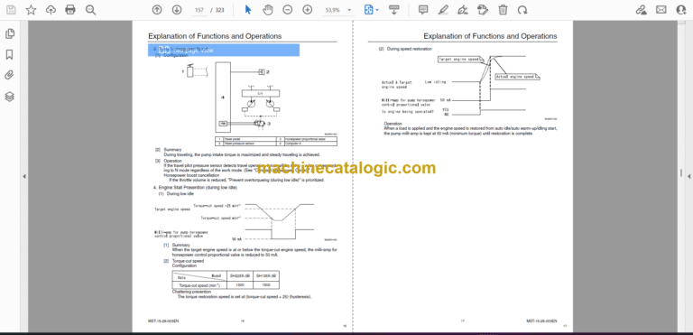
Explanation of Functions and Operations
Monitor Switch Panel ……………………………………………………………………………………..1
Explanation of Electrical Functions…………………………………………………………………..2
Engine Control………………………………………………………………………………………………5
1. Throttle Control…………………………………………………………………………………….5
2. One-touch Idle Control ………………………………………………………………………….6
3. Auto Warm-up ……………………………………………………………………………………..7
Engine Start/Stop Control……………………………………………………………………………….8
1. Neutral Start ………………………………………………………………………………………..8
2. Glow …………………………………………………………………………………………………..9
3. Idling Start …………………………………………………………………………………………10
4. Power-cut Delay …………………………………………………………………………………11
5. Engine Emergency Stop………………………………………………………………………12
6. EPF (protecting the engine from fatal trouble)…………………………………………13
Pump Control………………………………………………………………………………………………14
1. Work Mode Control……………………………………………………………………………..14
2. Constant Horsepower Control ………………………………………………………………15
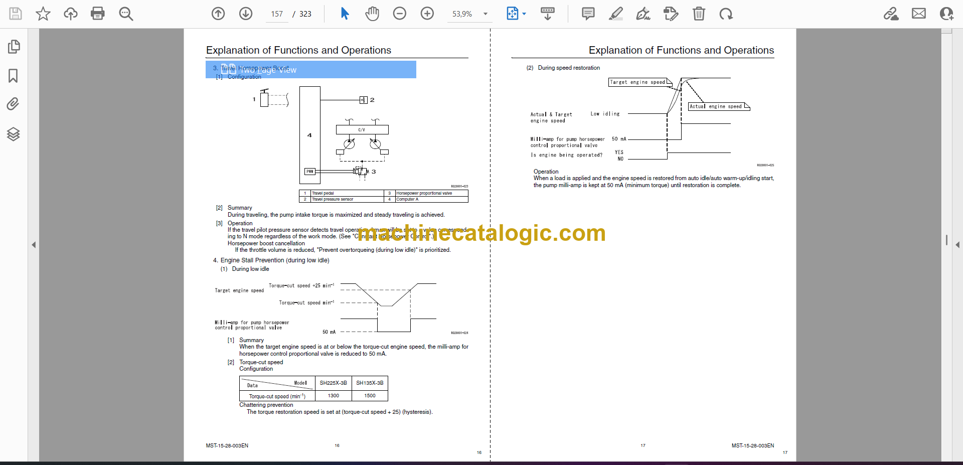
3. Travel Horsepower Boost……………………………………………………………………..16
4. Engine Stall Prevention (during low idle) ………………………………………………..16
5. High Altitude Correction ………………………………………………………………………19
Swing…………………………………………………………………………………………………………20
1. Swing Brake ………………………………………………………………………………………20
Travel …………………………………………………………………………………………………………21
1. Travel Speed Switchover ……………………………………………………………………..21
2. Travel Alarm……………………………………………………………………………………….22
Valve Control ………………………………………………………………………………………………23
1. Lever Lock …………………………………………………………………………………………23
2. Solenoid Sticking Prevention ………………………………………………………………..24
3. Pressure Boost Control ……………………………………………………………………….25
Monitor Control ……………………………………………………………………………………………26
1. Fuel Gauge/Refueling Warning …………………………………………………………….26
2. Coolant Temperature Gauge and
Oil Temperature Gauge/Overheat Warning …………………………………………27
3. Battery Charge Warning………………………………………………………………………29
4. Engine Oil Pressure Warning ……………………………………………………………….30
5. Hydraulic Oil Filter Clog Warning
(Function only with breaker, multi-purpose circuit) ………………………………32
6. Engine Abnormality Warning………………………………………………………………..34
7. Hour Meter ………………………………………………………………………………………..35
Accessories ………………………………………………………………………………………………..36
1. Horn………………………………………………………………………………………………….36
2. Working Light……………………………………………………………………………………..36
3. Backlight ……………………………………………………………………………………………37
4. Wiper and Washer………………………………………………………………………………37
5. Room Lamp……………………………………………………………………………………….40
6. Radio ………………………………………………………………………………………………..40
Other………………………………………………………………………………………………………….41
1. Key ON Alarm…………………………………………………………………………………….41
2. Battery Save Function …………………………………………………………………………41
Options ………………………………………………………………………………………………………43
1. Option Line Control …………………………………………………………………………….43
2. Model Setting …………………………………………………………………………………….47
Service Support…………………………………………………………………………………………..48
1. Rewriting Programs (engine information) ……………………………………………….48
2. Rewriting Programs (all reset/half reset) ………………………………………………..49
3. Managing Trouble States……………………………………………………………………..49
4. Diagnostic Lamp Output………………………………………………………………………52
5. Engine Controller Delivery Specifications ………………………………………………54
6. Engine-side Trouble…………………………………………………………………………….56
Service Support
Screen Operations……………………………………………………………………………………….66
1. Screen Shift……………………………………………………………………………………….66
Screen Display List ………………………………………………………………………………………68
1. CHK (status display) Screen List…………………………………………………………..68
2. DIAG (trouble diagnosis) Screen…………………………………………………………..80
3. HR (usage log) Screen List ………………………………………………………………….82
4. CFG (setting change) Screen……………………………………………………………….87
5. CAL (troubleshooting support) Screen …………………………………………………..91
6. Check the Monitor Switch (self-diagnosis function)………………………………….94
7. Model Setting …………………………………………………………………………………….95
8. Engine Screen Information …………………………………………………………………..97
Abnormality Display……………………………………………………………………………………..99
1. Main Unit Diagnostic Trouble Code List………………………………………………….99
2. Diagnostic Trouble Code (monitor display) ……………………………………………102
3. Sensor Trouble Operation Table ………………………………………………………….109
Main Equipment Structural Diagrams
Connection Connector Pin Layout ………………………………………………………………..111
1. Computer A ……………………………………………………………………………………..111
2. Monitor ……………………………………………………………………………………………112
Electrical Circuit Diagram
Overall View………………………………………………………………………………………………113
1. Sequence Circuit Diagram………………………………………………………………….113
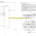
Block Diagram …………………………………………………………………………………………..115
1. Computer A ……………………………………………………………………………………..115
2. Computer S ……………………………………………………………………………………..116
3. ECM ……………………………………………………………………………………………….117
4. Monitor Display…………………………………………………………………………………118
5. Air Conditioner………………………………………………………………………………….119
6. Lever Lock ……………………………………………………………………………………….120
7. Horn………………………………………………………………………………………………..120
8. Other ………………………………………………………………………………………………120
9. Electrical Symbol List ………………………………………………………………………..121
Electrical Connector Wiring Diagram
Wire Harness…………………………………………………………………………………………….122
1. Main Frame Harness …………………………………………………………………………122
2. Cab Main Harness…………………………………………………………………………….125
3. Engine Harness………………………………………………………………………………..128
Electrical Equipment Layout Diagram
Overall View………………………………………………………………………………………………130
1. Main Unit Left Side Layout Diagram (radiator chamber) …………………………131
2. Engine Section Layout Diagram………………………………………………………….132
3. Engine Left Side Layout Diagram (pump chamber)………………………………..133
4. Main Unit Right Side Layout Diagram…………………………………………………..134
5. Cab Layout Diagram………………………………………………………………………….135
Stand Alone Parts Diagram…………………………………………………………………………137
Electrical Parts and Wiring Assembly Diagram
Upper Frame Electrical Parts and Wiring Assembly (1/4) ………………………………..148
Upper Frame Electrical Parts and Wiring Assembly (2/4) ………………………………..150
Upper Frame Electrical Parts and Wiring Assembly (engine) (3/4) ……………………151
Upper Frame Electrical Parts and Wiring Assembly (pump) (4/4) ……………………..153
Upper Frame Electrical Parts and Wiring Assembly ………………………………………..154
Maintenance Section
New Machine Performance
New Machine Performance Judgment Table ……………………………………………………..1
Performance Judgement Check Sheet …………………………………………………………1
Performance Measurement Entry Table………………………………………………………..2
Pressure Measurement and Adjustment Procedures
Pressure Measurement ………………………………………………………………………………….3
1. Basic Conditions…………………………………………………………………………………..3
2. Setting Value ……………………………………………………………………………………….3
3. Pressure Measuring Ports ……………………………………………………………………..4
4. Pressure Measurement Preparations………………………………………………………5
5. Pressure Measurement …………………………………………………………………………7
Pressure Adjustment ……………………………………………………………………………………..9
1. Pressure Adjustment Locations………………………………………………………………9
2. Air Bleed Procedures ………………………………………………………………………….11
Interchangeability
Main Part Commonality and Interchangeability Table………………………………………..12
SH135X-3 & SH135X-3B & SH130-5
Interchangeability Table (Mono-boom with blade) ………………………………..12
SH135X-3 Offset-boom and SH135X-3B Offset-boom
Interchangeability Table (Offset-boom with blade)………………………………..14
Attachment Installation Dimensions
Attachment Dimensions………………………………………………………………………………..14
Main Unit Weight
Divided Weight (standard specifications) SH135X-3B……………………………………….16
Stand Alone Part Weight ………………………………………………………………………………17
Shoe Weight (per side) …………………………………………………………………………………17
Arm Weight …………………………………………………………………………………………………17
Bucket Weight……………………………………………………………………………………………..18
