Format: PDF (Printable Document)
File Language: English
File Pages: 228
File Size: 7.69 MB (Speed Download Link)
Brand: Sumitomo
Model: SH290-3 Hydraulic Excavator
Book No: WLST2903-00W
Type of Document: Service Text
$ 45
Main Body Section
Specifications
Specifications …..•.•..•………………………•….•290-1-01-00-41 1
1/6
Complete Machine Dimensions , ….• 290-1-01-01-42 7
Standard Arm (3.20 m) 1/2
Short Arm (2.67 m) 1/2
Long Arm (3.66 m) 2/2
Work Range 290-1-01-02-42 9
Standard Arm (3.20 m) 1/3
Short Arm (2.67 m) 2/3
Long Arm (3.66 m) 3/3
Optional Components ………•..•.••.•………………. 290-1-01-03-16 12
List of Optional Components 1/1
Major Equipment Specifications
Equipment Configuration ……………………•….•….•290-2-01-00-11 13
Overall 1/2
Operator’s Cab 2/2
Lower Mechanism……………………….•..•••.••.•..290-2-01-01-39 15
Assembly Diagrams 1/3
Travel Unit (with parking brake) 2/3
Take-up Roller 2/3
Upper Roller 2/3
Lower Roller (external roller) 2/3
Recoil Spring 3/3
Shoes 3/3
Upper Mechanism …••……………..•.•..••..•••.••.•.•290-2-01-02-38 18
Swing Unit 1/1
Engine and Related Areas .•….•…•.•.•.•.•••..•………. 290-2-01-03-39 19
Engine 1/3
Muffler 2/3
Air Cleaner (double element) 2/3
Radiator 2/3
Fuel Tank 3/3
Hydraulic System …•.•…………………..••..••..•.•.290-2-01-04-40 22
Hydraulic Pump 1/3
Sump Tank 2/3
Rotating Joint. 3/3
Solenoid Valve 3/3
Controls ……………………………………•….••290-2-01-05-41 25
Remote Control Valve (left/right, travel operations) 1/2
Control Valve 2/2
Backhoe Attachments ………•………………………290-2-01-06-41 27
Cylinder 1/2
Attachments 2/2
290-1-00-00-18
Table of Contents Page No. 3/7
First Edition: 09/2004
Hydraulics Section
Hydraulic Pump 290-1-02-01-16 29
1. Structure and Principle of the Function 1/2
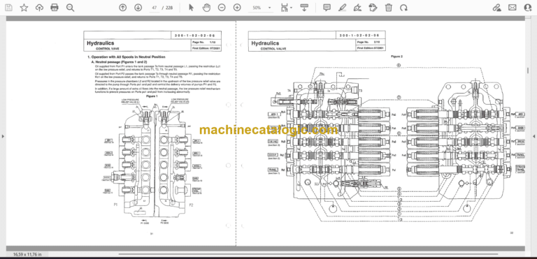
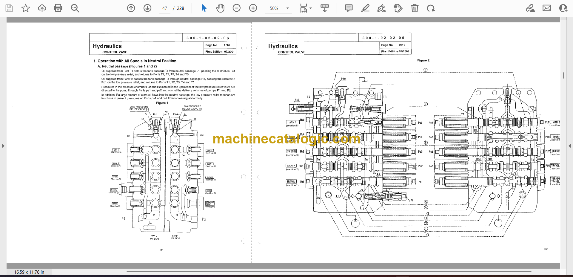
Control Valve 300-1-02-02-06 31
1. Operation with All Spools in Neutral Position 1/10
2. Separate Operation .4/10
Swing Unit 300-1-02-03-05 41
1. Configuration of Components 1/5
2. Structure of Hydraulic Motor 1/5
3. Operational Description of Hydraulic Motor 1/5
4. Operational Description of Mechanical Brake 2/5
5. Operational Description of Make-up Valve 2/5
6. Operational Description of Relief Valve
(Internal structural dawing of relief valve) 3/5
7. Operational Description of Bypass Valve
(Internal structural drawing of bypass valve) 3/5
Internal Structural Drawing 4/5
Internal Structural Drawing of Externally Adjusted Shockless Relief Valve 5/5
Internal Structural Drawing of Bypass Valve 5/5
Travel Unit
Travel Motor ………………………..•…••.•…..•..300-1-02-04-06 46
1. Structural Drawing 1/7
2. Structure 2/7
3. Functions .4/7
Brake Valve 300-1-02-04-08 53
1. Structure 1/5
2. Operation 2/5
Hydraulic Circuits Section
Port Locations 290-1-03-00-18 58
1. Hydraulic Pump 1/2
2. Control Valve 2/2
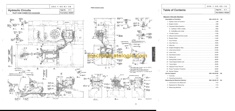
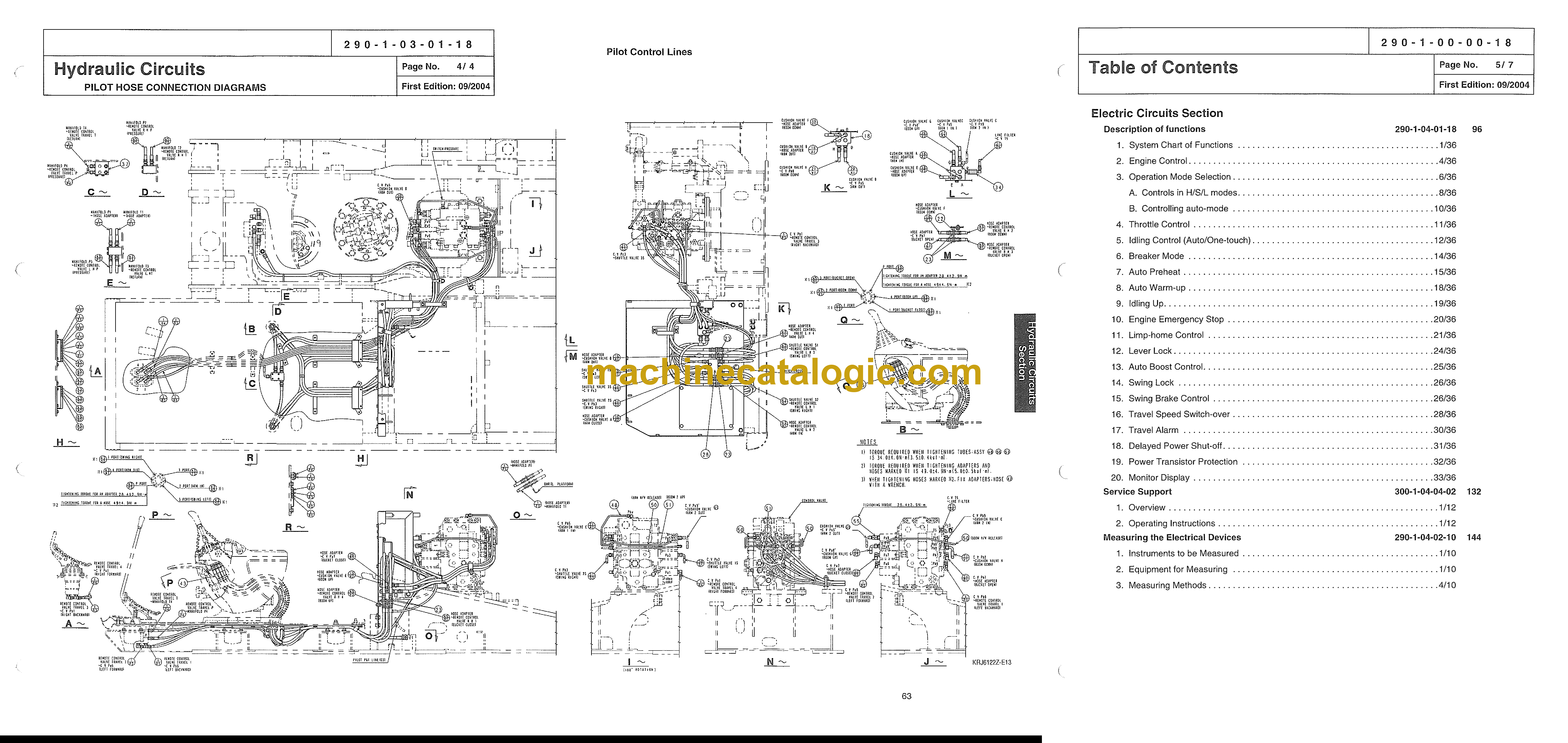
Pilot Hose Connection Diagrams 290-1-03-01-18 60
1. PilotP&TLines 1/4
2. Pilot Control Lines 3/4
List of Functions 290-1-03-02-17 64
List of Functions 1/2
Travel Circuits 290-1-03-03-13 66
1. High Speed Travel Circuit 1/6
2. Low Speed Travel Circuit. 3/6
3. Straight Travel Circuit 5/6
Swing Circuits 290-1-03-04-14 72
1. Swing Parking Circuit (Lever in Neutral/Swing Locked) 1/6
2. Swing Parking Circuit (with Brake Released) 3/6
3. Swing Push Digging 5/6
Arm Circuits 290-1-03-06-13 78
1. Arm-Out Circuit 1/6
2. Arm-In Load Holding 3/6
3. Arm-In Circuit. 5/6
Boom Circuits 290-1-03-07-13 84
1. Boom-Up Circuit (Single) 1/8
2. Boom-Up Circuit (Combined) 3/8
3. Boom-Down Load Holding 5/8
4. Boom-Down Circuit 7/8
Backup Circuit 290-1-03-09-11 92
1. Combined Circuit (Breaker Circuit) 1/4
2. Combined Circuit (High Speed Confluence Circuit) 3/4
(
290-1-00-00-18
Table of Contents Page No. 5/7
First Edition: 09/2004
Electric Circuits Section
Description of functions 290-1-04-01-18 96
1. System Chart of Functions 1/36
2. Engine Control .4/36
3. Operation Mode Selection 6/36
A. Controls in H/S/L modes 8/36
B. Controlling auto-mode 10/36
4. Throttle Control 11/36
5. Idling Control (Auto/One-touch) 12/36
6. Breaker Mode 14/36
7. Auto Preheat 15/36
8. Auto Warm-up 18/36
9. Idling Up 19/36
10. Engine Emergency Stop 20/36
11. Limp-home Control 21/36
12. Lever Lock 24/36
13. Auto Boost Control 25/36
14. Swing Lock 26/36
15. Swing Brake Control 26/36
16. Travel Speed Switch-over 28/36
17. Travel Alarm 30/36
18. Delayed Power Shut-off. 31/36
19. Power Transistor Protection 32/36
20. Monitor Display 33/36
Service Support 300-1-04-04-02 132
1. Overview 1/12
2. Operating Instructions 1/12
Measuring the Electrical Devices 290-1-04-02-10 144
1. Instruments to be Measured 1/10
2. Equipment for Measuring 1/10
3. Measuring Methods .4/10
Initial Controller Settings 300-1-04-05-02 154
1. Verifying the Settings 1/2
2. Resetting Procedures 1/2
3. Setting Procedures 1/2
4.~~~ngs m
5. Error Display Functions 2/2
Troubleshooting 300-1-04-06-03 156
1. Problem Symptoms 1/13
2. Inspections Prior to Troubleshooting 2/13
3. Troubleshooting Procedures 3/13
4. Using the Flow Chart .4/13
5. Diagnosis 5/13
A. Refilling fuel 5/13
B. Refilling coolant 6/13
C. Low engine oil pressure 7/13
D. Overheat. 8/13
E. Battery charging 10/13
F. Faulty electrical system 11/13
G. Engine controls 13/13
Electric Wiring Diagrams 290-1-04-07-15 169
Electrical Components and Wiring for Upper Frame 1/2
Electrical Components and Wiring for Cab 2/2
Harness Diagrams 290-1-04-08-15 171
Upper Frame 1/2
Inside Cab 2/2
290-1-05-00-19 180
290-1-00-00-18
Table of Contents Page No. 7/7
First Edition: 09/2004
Maintenance Section
New Machine Performance
Performance Evaluation Table 000-3-02-00-13 173
1. Perioarmance Evaluation Check Sheet 1/2
2. Periormance Evaluation Recording Sheet 2/2
Reference Values 290-3-02-01-16 175
1/1
Main Body Weight 290-3-01-00-39 176
1. Major Component Weight (Standard specifications) 1/3
2. Individual Part Weight. 2/3
3. Shoe Weight (One side) 2/3
4. Arm Weight. 2/3
5. Bucket Weight. 3/3
Attachments Dimensions 290-1-05-04-13 179
1/1
Instructions for Measuring and Adjusting Pressure
1. Measuring Pressure
A. Basic conditions 1/14
B. Set values 1/14
C. Pressure measuring port 2/14
D. Preparation for measuring pressure .4/14
E. Measuring pressure 6/14
F. Measuring other pressures 8/14
2. Adjusting Pressure
A. Pressure Adjusting Points 9/14
B. Instructions for Adjusting Pressure 11/14
Compatibility 290-1-05-05-16 194
List of Compatibility of Main Parts 1/2
Appendix
Unit Conversion Table 300-1-08-01-02 196
1/1
New Hydraulic Oil 300-1-08-02-02 197
Long-life hydraulic oil (IDEMITSU Daphne Super Hydro 46SX) 1/1
Circuit diagrams (located inside the pocket at back of back cover)
Hydraulic Circuit Diagram (A1)
Electric Circuit Diagram (A1)