Format: PDF
Language: EN
Size: 44.98 MB
Pages: 332
Speed Download Link
$ 50 Original price was: $ 50.$ 40Current price is: $ 40.
YANMAR SV100 SERVICE MANUAL contains high quality images, diagrams, instructions to help you to operate, maintenance, diagnostic, and repair your machine. This document is printable, without restrictions, contains searchable text and bookmarks for easy navigation.
CHAPTER 1
GENERAL CAUTIONS FOR MAINTENANCE WORK
1-1 Correct Work ………………………………………………………………………………………………………………………………………………………1-1
1-2 Safety Precautions ………………………………………………………………………………………………………………………………………………1-1
1-3 Preparations……………………………………………………………………………………………………………………………………………………….1-1
1-4 Cautions for Disassembly and Reassembly…………………………………………………………………………………………………………….1-1
1-5 Cautions for Removal and Installation of Hydraulic Equipment ………………………………………………………………………………….1-2
1-6 Cautions for Removal and Installation of Hydraulic Piping…………………………………………………………………………………………1-2
1-7 Cautions for Handling Seals………………………………………………………………………………………………………………………………….1-3
1-8 Correct Installation of Hydraulic Hose …………………………………………………………………………………………………………………….1-3
1-9 Specifications of Hydraulic Hose……………………………………………………………………………………………………………………………1-6
1-10 Air Release of Hydraulic Equipment……………………………………………………………………………………………………………………1-11
CHAPTER 2
TECHNICAL DATA
2-1 Specifications …………………………………………………………………………………………………………………………………………………. 2-1-1
2-2 Outline Drawing and Working Area……………………………………………………………………………………………………………………. 2-2-1
2-2-1 Quick coupler …………………………………………………………………………………………………………………………………………. 2-2-1
2-2-2 W/O Quick coupler ………………………………………………………………………………………………………………………………….. 2-2-2
2-3 Weight List of Main Parts …………………………………………………………………………………………………………………………………. 2-3-1
2-4 Lifting Capacity List …………………………………………………………………………………………………………………………………………. 2-4-1
2-4-1 SV100……………………………………………………………………………………………………………………………………………………. 2-4-1
CHAPTER 3
SERVICE STANDARDS
3-1 Machine Performance ……………………………………………………………………………………………………………………………………… 3-1-1
3-2 Engine …………………………………………………………………………………………………………………………………………………………… 3-2-1
3-3 Undercarriage ………………………………………………………………………………………………………………………………………………… 3-3-1
3-3-1 Rubber Crawler Specifications ………………………………………………………………………………………………………………….. 3-3-1
3-3-2 Steel Crawler Specifications……………………………………………………………………………………………………………………… 3-3-2
3-3-3 Common Specifications of Steel & Rubber Crawlers ……………………………………………………………………………………. 3-3-3
3-4 Controls…………………………………………………………………………………………………………………………………………………………. 3-4-1
3-5 Hydraulic Equipment ……………………………………………………………………………………………………………………………………….. 3-5-1
3-5-1 Hydraulic Cylinders …………………………………………………………………………………………………………………………………. 3-5-1
3-6 Implement ……………………………………………………………………………………………………………………………………………………… 3-6-1
3-6-1 Front Attachments (Quick Coupler Type)……………………………………………………………………………………………………. 3-6-1
3-6-2 Blade Moving Device……………………………………………………………………………………………………………………………….. 3-6-2
3-6-3 Bucket Teeth ………………………………………………………………………………………………………………………………………….. 3-6-2
3-7 List of Tightening Torque …………………………………………………………………………………………………………………………………. 3-7-1
3-7-1 Machine…………………………………………………………………………………………………………………………………………………. 3-7-1
3-7-2 Engine …………………………………………………………………………………………………………………………………………………… 3-7-4
3-7-3 Tightening Torque for General Bolts and Nuts…………………………………………………………………………………………….. 3-7-4
CHAPTER 4
ENGINE
4-1 General …………………………………………………………………………………………………………………………………………………………. 4-1-1
4-1-1 How to Read This Manual ………………………………………………………………………………………………………………………… 4-1-1
4-1-2 Precautions for Service Work……………………………………………………………………………………………………………………. 4-1-3
4-1-3 Engine External Views ……………………………………………………………………………………………………………………………. 4-1-4
4-1-4 Structural Description ……………………………………………………………………………………………………………………………… 4-1-4
4-1-5 Exhaust Gas Emission Regulation …………………………………………………………………………………………………………….. 4-1-5
4-2 Troubleshooting ……………………………………………………………………………………………………………………………………………… 4-2-1
4-2-1 Quick Reference Table for Troubleshooting………………………………………………………………………………………………… 4-2-1
4-2-2 Troubleshooting by Measuring Compression Pressure ………………………………………………………………………………… 4-2-4
4-3 Inspection and Adjustment……………………………………………………………………………………………………………………………….. 4-3-1
4-3-1 Oil Inspection………………………………………………………………………………………………………………………………………….. 4-3-1
4-3-2 Cooling Water Inspection …………………………………………………………………………………………………………………………. 4-3-1
4-3-3 Inspecting Water Leak from Cooling Water System and Radiator ………………………………………………………………….. 4-3-1
4-3-4 Fan Belt Tension Inspection and Adjustment………………………………………………………………………………………………. 4-3-2
4-3-5 Adjusting the Valve Clearance ………………………………………………………………………………………………………………….. 4-3-3
4-3-6 Inspecting the Fuel Injection Valve Injection Pressure and Spray Pattern……………………………………………………….. 4-3-5
4-3-7 Fuel Injection Timing Adjustment / Fuel Injection Pump Inspection and Adjustment …………………………………………. 4-3-9
4-3-8 Sensor Inspection………………………………………………………………………………………………………………………………….. 4-3-12
4-3-9 Battery Inspection………………………………………………………………………………………………………………………………….. 4-3-13
4-3-10 Adjusting Operation……………………………………………………………………………………………………………………………… 4-3-15
4-3-11 Long Storage………………………………………………………………………………………………………………………………………. 4-3-16
4-3-12 Periodic Maintenance Schedule…………………………………………………………………………………………………………….. 4-3-17
4-4 Engine Body…………………………………………………………………………………………………………………………………………………… 4-4-1
4-4-1 Introduction…………………………………………………………………………………………………………………………………………….. 4-4-1
4-4-2 Cylinder Head…………………………………………………………………………………………………………………………………………. 4-4-2
4-4-3 Gear Train and Camshaft……………………………………………………………………………………………………………………….. 4-4-10
4-4-4 Cylinder Block ………………………………………………………………………………………………………………………………………. 4-4-15
4-5 Lubrication System………………………………………………………………………………………………………………………………………….. 4-5-1
4-5-1 Lubrication System Diagram …………………………………………………………………………………………………………………….. 4-5-1
4-5-2 Trochoid Pump Components…………………………………………………………………………………………………………………….. 4-5-1
4-5-3 Disassembly (Reverse the Procedure Below for Assembly) ………………………………………………………………………….. 4-5-2
4-5-4 Servicing Points………………………………………………………………………………………………………………………………………. 4-5-2
4-5-5 Parts Inspection and Measurement……………………………………………………………………………………………………………. 4-5-2
4-6 Cooling System………………………………………………………………………………………………………………………………………………. 4-6-1
4-6-1 Cooling Water System……………………………………………………………………………………………………………………………… 4-6-1
4-6-2 Cooling Water Pump Components…………………………………………………………………………………………………………….. 4-6-1
4-6-3 Disassembly (Reverse the Procedure Below for Assembly) ………………………………………………………………………….. 4-6-2
4-6-4 Servicing Points………………………………………………………………………………………………………………………………………. 4-6-2
4-7 Fuel Injection Pump / Governor…………………………………………………………………………………………………………………………. 4-7-1
4-7-1 Introduction…………………………………………………………………………………………………………………………………………….. 4-7-1
4-7-2 Fuel Injection Pump…………………………………………………………………………………………………………………………………. 4-7-1
4-8 Turbocharger : Disassembly, Inspection and Reassembly ……………………………………………………………………………………. 4-8-1
4-8-1 Structure and Functions …………………………………………………………………………………………………………………………… 4-8-1
4-8-2 Service Standards and Tightening Torque………………………………………………………………………………………………….. 4-8-4
4-8-3 Periodic Inspection Procedure ………………………………………………………………………………………………………………….. 4-8-5
4-8-4 Disassembly Procedure …………………………………………………………………………………………………………………………… 4-8-9
4-8-5 Washing and Inspection procedure………………………………………………………………………………………………………….. 4-8-12
4-8-6 Reassembly Procedure ………………………………………………………………………………………………………………………….. 4-8-16
4-8-7 Handling after Disassembly and Reassembly……………………………………………………………………………………………. 4-8-19
4-8-8 Troubleshooting…………………………………………………………………………………………………………………………………….. 4-8-20
4-9 Starting motor…………………………………………………………………………………………………………………………………………………. 4-9-1
4-9-1 Specifications …………………………………………………………………………………………………………………………………………. 4-9-1
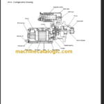
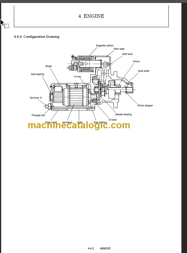
4-9-2 Configuration Drawing……………………………………………………………………………………………………………………………… 4-9-2
4-9-3 Troubleshooting………………………………………………………………………………………………………………………………………. 4-9-3
4-9-4 Component Names and Disassembly Procedure ………………………………………………………………………………………… 4-9-4
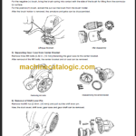
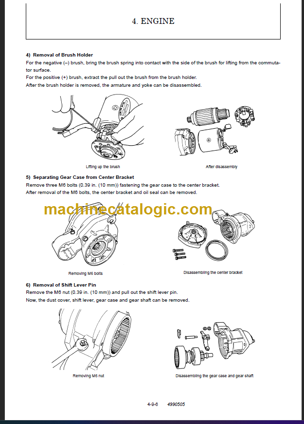
4-9-5 Disassembly Procedure …………………………………………………………………………………………………………………………… 4-9-5
4-9-6 Inspection and Maintenance …………………………………………………………………………………………………………………….. 4-9-7
4-9-7 Assembly……………………………………………………………………………………………………………………………………………… 4-9-11
4-9-8 Adjustment …………………………………………………………………………………………………………………………………………… 4-9-12
4-9-9 Service Standards …………………………………………………………………………………………………………………………………. 4-9-13
4-10 Alternator……………………………………………………………………………………………………………………………………………………. 4-10-1
4-10-1 Specifications ……………………………………………………………………………………………………………………………………… 4-10-1
4-10-2 Section View……………………………………………………………………………………………………………………………………….. 4-10-2
4-10-3 Troubleshooting…………………………………………………………………………………………………………………………………… 4-10-3
4-10-4 Parts Names and Disassembly Procedure………………………………………………………………………………………………. 4-10-4
4-10-5 Inspection and Overhaul ………………………………………………………………………………………………………………………. 4-10-7
4-10-6 Assembly………………………………………………………………………………………………………………………………………….. 4-10-11
4-10-7 Service Standards ……………………………………………………………………………………………………………………………… 4-10-12
4-10-8 Performance Test………………………………………………………………………………………………………………………………. 4-10-13
4-11 Special Service Tools…………………………………………………………………………………………………………………………………… 4-11-1
4-11-1 Special Tools………………………………………………………………………………………………………………………………………. 4-11-1
4-11-2 Measuring Instruments…………………………………………………………………………………………………………………………. 4-11-3
4-12 Service Standards……………………………………………………………………………………………………………………………………….. 4-12-1
4-12-1 Engine Turning ……………………………………………………………………………………………………………………………………. 4-12-1
4-12-2 Engine Body……………………………………………………………………………………………………………………………………….. 4-12-2
4-12-3 Lubricating Oil System (Trochoid Pump)…………………………………………………………………………………………………. 4-12-6
4-12-4 Tightening Torques for Main Parts …………………………………………………………………………………………………………. 4-12-7
CHAPTER 5
HYDRAULIC SYSTEM
5-1 Outline (Quick Coupler Type)……………………………………………………………………………………………………………………………. 5-1-1
5-1-1 Control Valve Operation …………………………………………………………………………………………………………………………… 5-1-3
5-1-2 Additional Operation of Control Valve ………………………………………………………………………………………………………… 5-1-4
5-2 Hydraulic Circuit Schematic ……………………………………………………………………………………………………………………………… 5-2-1