Format: PDF (Printable Document)
File Language: English
File Pages: 252
File Size: 4.69 MB (Speed Download Link)
Brand: BT
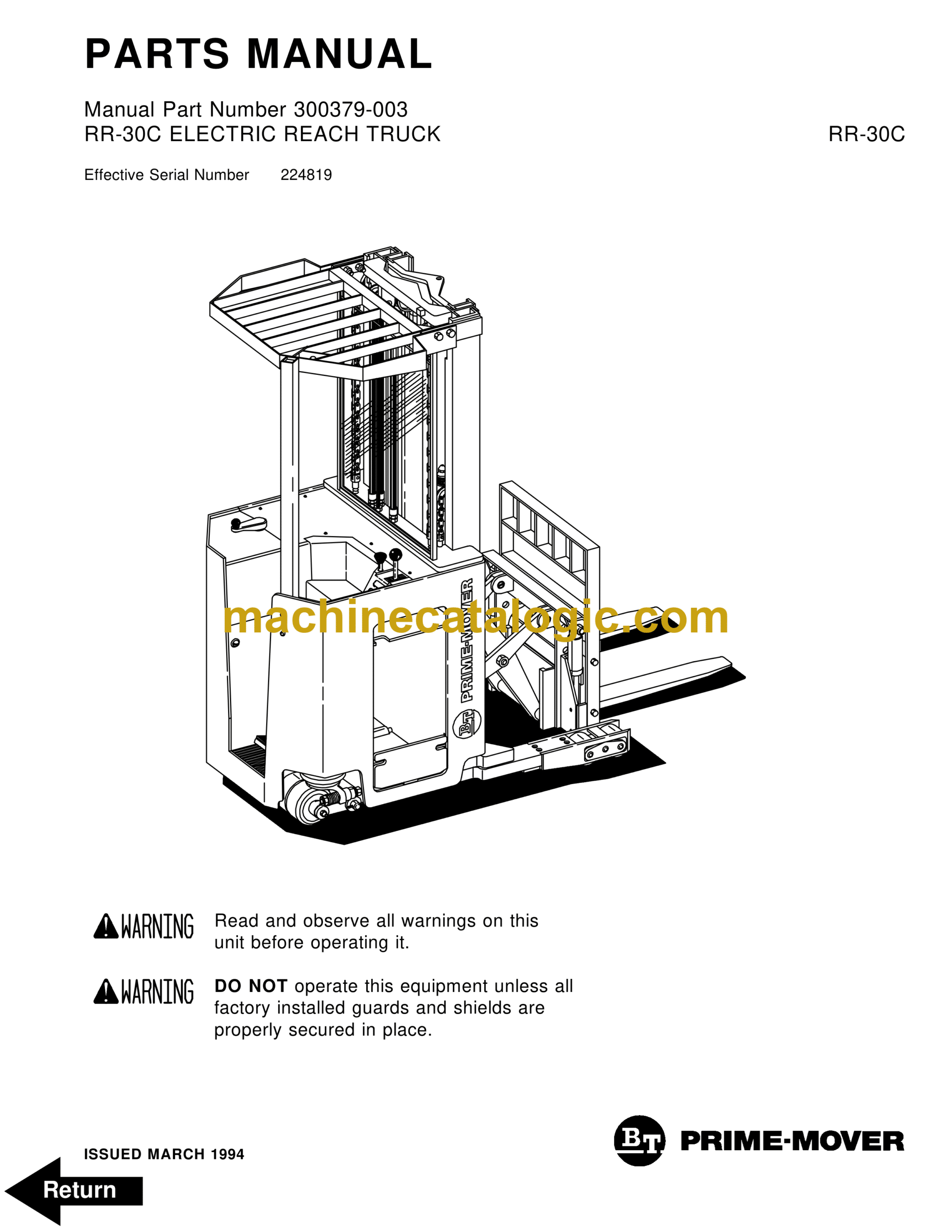
Model: RR30C
Type of Document: Operators Manual
$ 40
Front Cover
Parts Ordering Instructions
Field Modifications
General Information
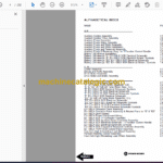
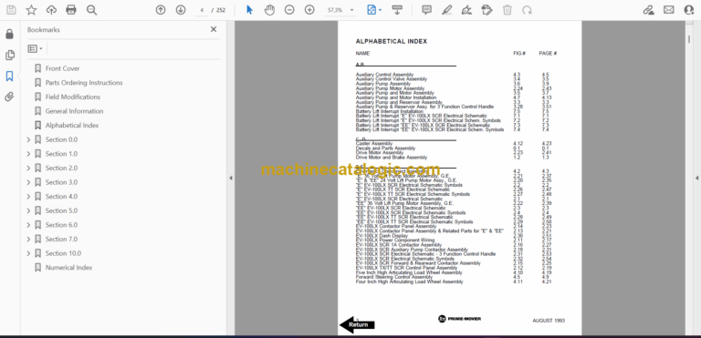
Alphabetical Index
Section 0.0
Figure # 0.1 Decals and Parts Assembly
Section 1.0
Figure # 1.1 Transmission and Drive Motor Installation
Figure # 1.2 Drive Motor and Brake Assembly
Figure # 1.3 Transmission Assembly Part #1
Figure # 1.4 Transmission Assembly Part #2
Section 2.0
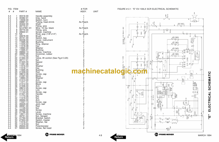
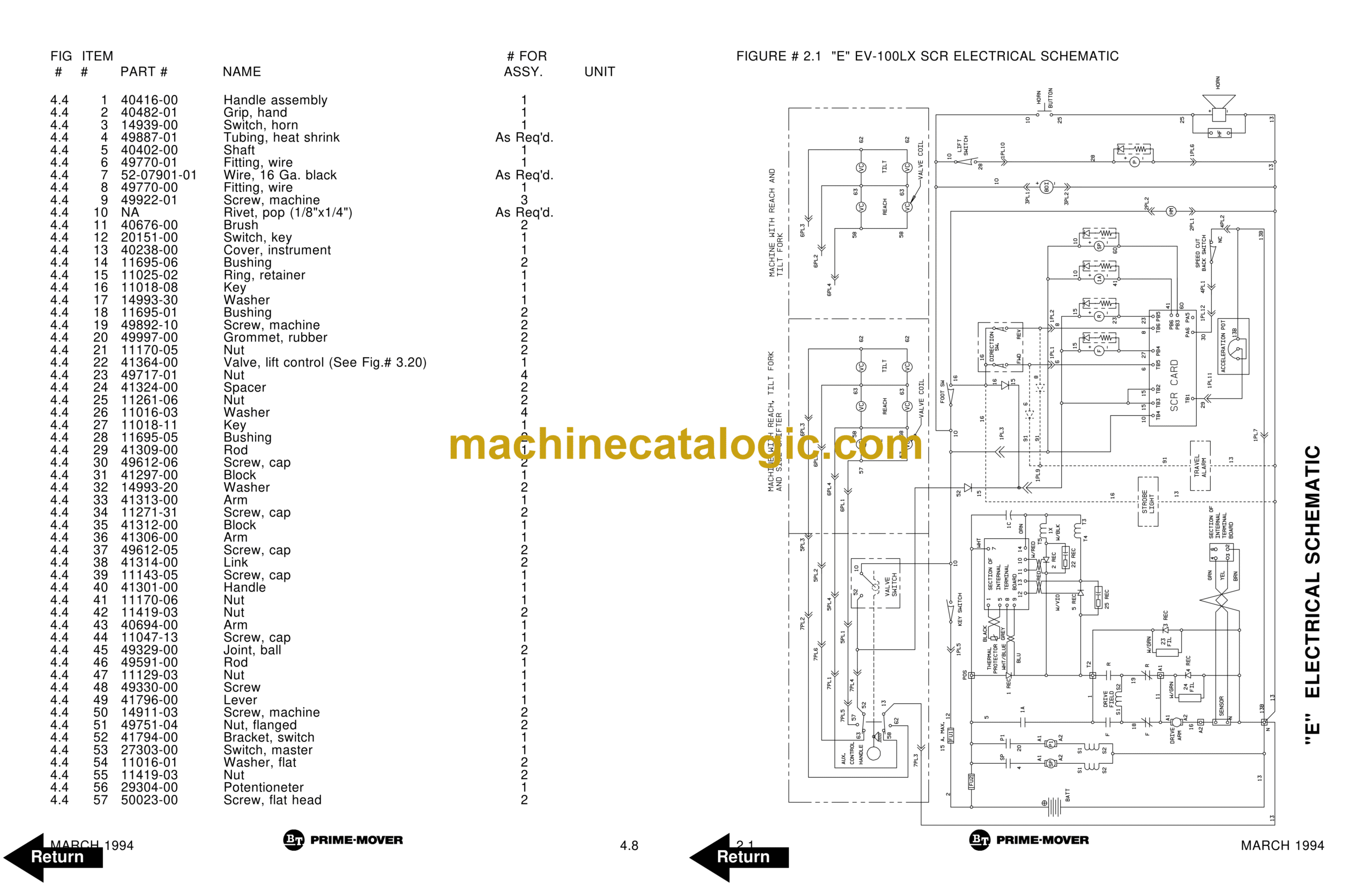
Figure # 2.1 “E” EV-100LX SCR Electrical Schematic
Figure # 2.2 “E” EV-100LX SCR Electrical Schematic Symbols
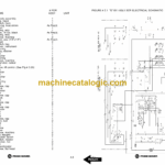
Figure # 2.3 “EE” EV-100LX SCR Electrical Schematic
Figure # 2.4 “EE” EV-100LX SCR Electrical Schematic Symbols
Figure # 2.5 Wiring Assembly for Cold Storage
Figure # 2.6 Wiring Harness Assembly
Figure # 2.7 Limit Switch Wiring Assembly
Figure # 2.8 Two Stage Mast Cable Assembly
Figure # 2.9 Three Stage Mast Cable Assembly
Figure # 2.10 Reach Cable Assembly
Figure # 2.11 EV-100LX Power Component Wiring
Figure # 2.12 EV-100LX TX & TT SCR Control Panel Assembly
Figure # 2.13 EV-100LX Contactor Panel Assembly & Related Parts for “E” and “EE”
Figure # 2.14 EV-100LX Contactor Panel Assembly
Figure # 2.15 EV-100LX SCR Forward & Rearward Contactor Assembly
Figure # 2.16 EV-100LX SCR 1A Contactor Assembly
Figure # 2.17 Lift Pump Contactor Assembly
Figure # 2.18 EV-100LX SCR Auxiliary Pump Contactor Assembly
Figure # 2.19 Power Connector Assembly
Figure # 2.20 Lift Pump Motor Assembly
Figure # 2.21 Lift Pump Motor Assembly, 36 Volt
Figure # 2.22 Drive Motor Assembly
Figure # 2.23 Auxiliary Pump Motor Assembly
Figure # 2.24 Warning Light Assembly
Figure # 2.25 “E” EV-100LX TT SCR Electrical Schematic
Figure # 2.26 “E” EV-100LX TT SCR Electrical Schematic Symbols
Figure # 2.27 “EE” EV-100LX TT SCR Electrical Schematic
Figure # 2.28 “EE” EV-100LX TT SCR Electrical Schematic Symbols
Figure # 2.29 EV-100LX Dash Display Installation
Figure # 2.30 EV-100LX SCR Electrical Schematic – 3 Function Control Handle
Figure # 2.31 EV-100LX SCR Electrical Schematic Symbols
Figure # 2.30A TX EV-100LX Electrical Schematic – 3 Function Control Handle
Figure # 2.31A EV-100LX SCR Electrical Schematic Symbols
Figure # 2.30B TT EV-100LX Electrical Schematic – 3 Function Control Handle
Figure # 2.31B EV-100LX SCR Electrical Schematic Symbols
Figure # 2.32 Wiring Harness Assembly for 3 Function Control Valve
Section 3.0
Figure # 3.1 Hydraulic Schematic
Figure # 3.2 Hydraulic Schematic Symbols
Figure # 3.3 Auxiliary Pump and Reservoir Assembly
Figure # 3.4 Auxiliary Control Valve Assembly
Figure # 3.5 Auxiliary Pump and Motor Assembly
Figure # 3.6 Auxiliary Pump Assembly
Figure # 3.7 Hydraulic Reservoir Assembly
Figure # 3.8 Torque Generator Assembly
Figure # 3.9 Two Stage Mast Hydraulic Assembly
Figure # 3.10 Three Stage Mast Hydraulic Assembly
Figure # 3.11 Reach Cylinder Hose Installation
Figure # 3.12 Reach Diverter Valve Assembly
Figure # 3.13 Reach Cylinder Assembly
Figure # 3.14 Tilt and Sideshift Hose Installation
Figure # 3.15 Tilt Cylinder Assembly
Figure # 3.16 Lift Pump and Reservoir Assembly
Figure # 3.17 Lift Pump Motor Assembly
Figure # 3.18 Lift Pump Assembly
Figure # 3.19 Lift Pump Motor Assembly, 36 Volt
Figure # 3.20 Lift Control Valve Assembly
Figure # 3.21 Two Stage Cylinder and Reservoir Assembly
Figure # 3.22 Two Stage Cylinder Assembly
Figure # 3.23 Three Stage Cylinder and Reservoir Assembly
Figure # 3.24 Three Stage Staging Cylinder Assembly
Figure # 3.25 Three Stage Freelift Cylinder Assembly
Figure # 3.26 Hydraulic Schematic for 3 Function Control Handle
Figure # 3.27 Hydraulic Schematic Symbols
Figure # 3.28 Auxiliary Pump & Reservoir Assembly for 3 Function Control Handle
Figure # 3.29 Valve Assembly
Figure # 3.30 Two Stage Mast Hydraulic Assembly for 3 Function Control Handle
Figure # 3.31 Three Stage Mast Hydraulic Assembly for 3 Function Control Handle
Section 4.0
Figure # 4.1 Shielding Assembly
Figure # 4.2 Emergency Disconnect Assembly
Figure # 4.3 Auxiliary Control Assembly
Figure # 4.4 Hand Lift/Lower and Speed Control
Figure # 4.5 Forward Steering Control Assembly
Figure # 4.6 Rearward Steering Control Assembly
Figure # 4.7 Auxiliary Pump and Motor Installation
Figure # 4.8 Main Frame and Load Wheel Assembly
Figure # 4.9 Single Load Wheel Assembly
Figure # 4.9A Single Load Wheel Assembly
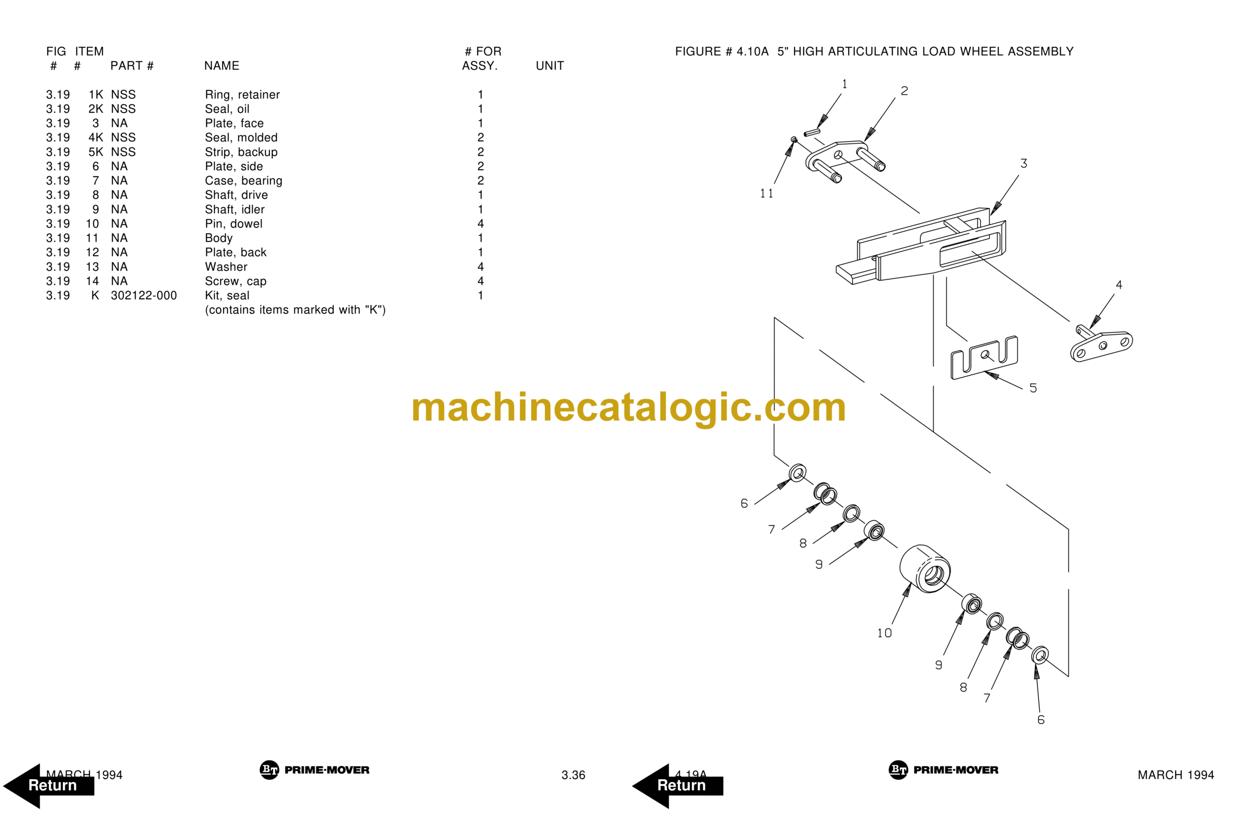
Figure # 4.10 5″ High Articulating Load Wheel Assembly
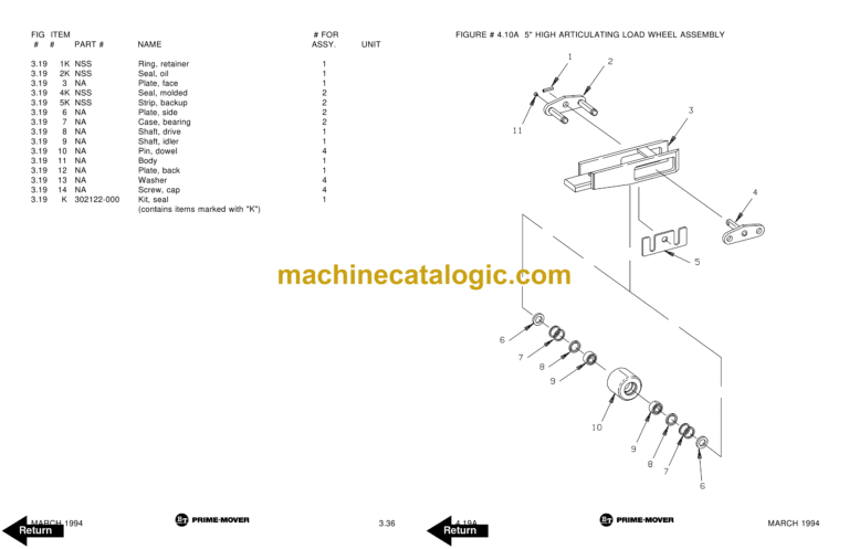
Figure # 4.10A 5″ High Articulating Load Wheel Assembly
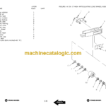
Figure # 4.11 4″ High Articulating Load Wheel Assembly
Figure # 4.11A 4″ High Articulating Load Wheel Assembly
Figure # 4.12 Caster Assembly
Figure # 4.13 Hand Lift/Lower and Speed Control for 3 Function Control
Section 5.0
Figure # 5.1 Two Stage Mast Installation
Figure # 5.2 Two Stage Inner Column Assembly
Figure # 5.3 Two Stage Outer Column Assembly
Figure # 5.4 Two Stage Cylinder Assembly
Figure # 5.5 Two Stage Reach Assembly
Figure # 5.6 Two Stage Reach Front Frame
Figure # 5.7 Two Stage Sideshifter Assembly
Figure # 5.8 Two Stage Fork Assembly
Figure # 5.9 Three Stage Mast Installation
Figure # 5.10 Three Stage Inner Column Assembly
Figure # 5.11 Three Stage Freelift Cylinder Installation
Figure # 5.12 Three Stage Intermediate Column Assembly
Figure # 5.13 Three Stage Outer Column Assembly
Figure # 5.14 Three Stage Reach Assembly
Figure # 5.15 Three Stage Reach Front Frame
Figure # 5.16 Three Stage Sideshifter Assembly
Figure # 5.17 Three Stage Fork Assembly
Section 6.0
Figure # 6.1 Remote Lift/Lower EV-100 LX SCR Electrical Schematic
Figure # 6.2 Remote Lift/Lower EV-100 LX SCR Electrical Schematic Symbols
Figure # 6.3 Remote Lift/Lower Wiring Harness Assembly
Figure # 6.4 Remote Lift/Lower Three Stage Mast Cable Assembly
Figure # 6.5 Remote Lift/Lower Reach and Platform Cable Assembly
Figure # 6.6 Remote Lift/Lower Power Component Wiring
Figure # 6.7 Remote Lift/Lower Connector Assembly
Figure # 6.8 Remote Lift/Lower Hydraulic Schematic
Figure # 6.9 Remote Lift/Lower Manlift Hydraulic Schematic Symbols
Figure # 6.10 Remote Lift/Lower Hydraulic Diagram
Figure # 6.11 Blocking Remote Lift/Lower Valve Assembly
Figure # 6.12 Remote Lift/Lower Valve Assembly
Figure # 6.13 Remote Lift/Lower Load Backrest Installation
Figure # 6.14 Remote Lift/Lower Contactor Assembly
Section 7.0
Figure # 7.1 Battery Lift Interrupt “E” EV-100LX SCR Electrical Schematic
Figure # 7.2 Battery Lift Interrupt “E” EV-100LX SCR Electrical Schematic Symbols
Figure # 7.3 Battery Lift Interrupt “EE” EV-100LX SCR Electrical Schematic
Figure # 7.4 Battery Lift Interrupt “EE” EV-100LX SCR Electrical Schematic Symbols
Figure # 7.5 Battery Lift Interrupt Installation
Section 10.0
Figure # 10.1 Special Tools and Lubrications
Numerical Index