Format: PDF (Printable Document)
File Language: English
Brand: BT
Model: SN20, SN30, SN40 Electric Stacker
Type of Document: Maintenance, Operator and Parts Manual
$ 70
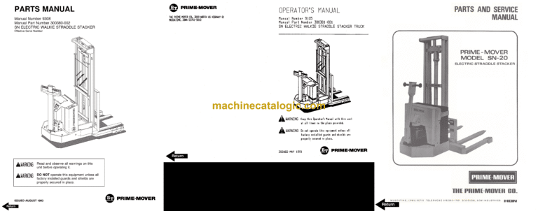
BT SN20, SN30, SN40 Electric Stacker Maintenance, Operator and Parts Manual
Front Cover
Parts Ordering Instructions
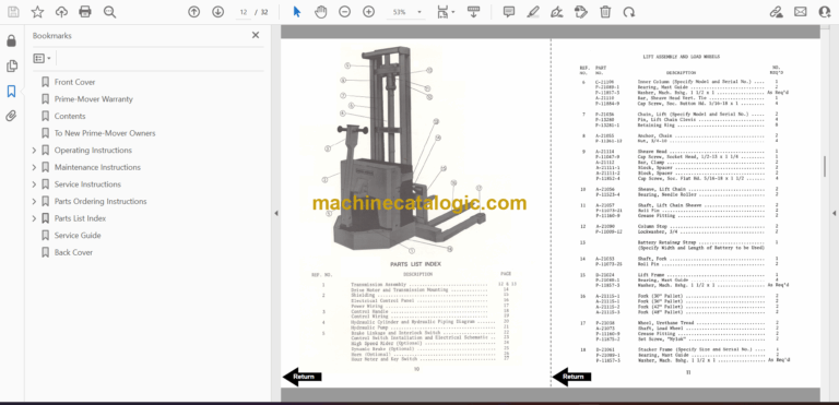
General Information
Alphabetical Index
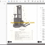
Figure # 0.1 Decals and Parts Assembly
Figure # 1.1 Transmission and Handle Assembly
Figure # 1.2 Twist Grip Resistor & Transistor Control Handle Assembly
Figure # 1.3 Thumb Control Resistor & Transistor Control Handle Assembly
Figure # 1.4 Transmission Assembly, Part # 1
Figure # 1.5 Transmission Assembly, Part # 2
Figure # 1.6 Drive Motor Assembly
Figure # 2.1 Resistor Electrical Schematic
Figure # 2.2 Resistor Electrical Schematic Symbols
Figure # 2.3 Resistor Control Wiring Harness Assembly
Figure # 2.4 Resistor Power Component Wiring
Figure # 2.5 Control Panel Assembly
Figure # 2.6 Second Speed Contactor Assembly
Figure # 2.7 Forward & Rearward Contactor Assembly
Figure # 2.8 Power Connector Assembly
Figure # 2.9 Bosch Hydraulic Pump Motor Assembly
Figure # 2.10 12 Volt Drive Motor Assembly
Figure # 2.11 24 Volt Drive Motor Assembly
Figure # 2.12 Pump Motor Assembly
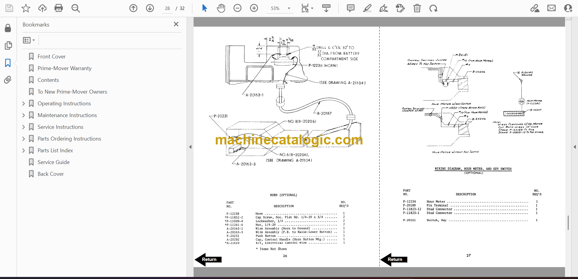
Figure # 2.13 Warning Light Assembly
Figure # 2.14 Transistor Electrical Schematic
Figure # 2.15 Transistor Electrical Schematic Symbols
Figure # 2.16 Transistor Control Wiring Harness Assembly
Figure # 2.17 Control Wiring Harness
Figure # 2.18 Control Panel Assembly
SN-20 Hydraulic Section
SN-30 Hydraulic Section
SN-40 Hydraulic Section
Figure # 4.1 Shielding Assembly
Figure # 4.2 Main Frame and Load Wheel Installation
Figure # 4.3 Caster Assembly
Figure # 4.4 Two/Three Spool Control Valve Mounting Assembly
Figure # 4.5 Pallet Centering Device
Figure # 5.1 SN-20/30 Two Stage Mast Installation
Figure # 5.2 SN-20/30 Two Stage Outer Column Assembly (Frame)
Figure # 5.3 SN-20/30 Two Stage Inner Column Assembly
Figure # 5.4 SN-20/30 Two Stage Mast Cylinder and Related Parts
Figure # 5.5 SN-20/30 Two Stage Mast Lift Frame and Load Backrest Assembly
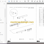
Figure # 5.6 SN-20/30 Two Stage Fork Assembly
Figure # 5.7 SN-20/30 Three Stage Mast Installation
Figure # 5.8 SN-20/30 Three Stage Mast Outer Column Assembly
Figure # 5.9 SN-20/30 Three Stage Mast Intermediate Column Assembly
Figure # 5.10 SN-20/30 Three Stage Mast Inner Column Assembly
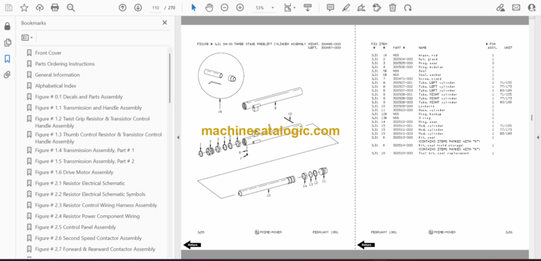
Figure # 5.11 SN-20/30 Three Stage Mast Freelift Cylinder and Related Parts
Figure # 5.12 SN-20/30 Three Stage Mast Lift Frame and Backrest Assembly
Figure # 5.13 SN-20/30 Three Stage Fork Assembly
Figure # 5.14 SN-40 Two Stage Mast Installation
Figure # 5.15 SN-40 Two Stage Mast Outer Column Assembly
Figure # 5.16 SN-40 Two Stage Mast Inner Column Assembly
Figure # 5.17 SN-40 Two Stage Mast Cylinder and Related Parts
Figure # 5.18 SN-40 Two Stage Mast Lift Frame and Load Backrest Assembly
Figure # 5.19 SN-40 Two Stage Fork Assembly
Figure # 5.20 SN-40 Three Stage Mast Installation
Figure # 5.21 SN-40 Three Stage Mast Outer Column Assembly
Figure # 5.22 SN-40 Three Stage Mast Intermediate Column Assembly
Figure # 5.23 SN-40 Three Stage Mast Inner Column Assembly
Figure # 5.24 SN-40 Three Stage Mast Freelift Cylinder Installation
Figure # 5.25 SN-40 Three Stage Mast Lift Frame and Load Backrest Assembly
Figure # 5.26 SN-40 Three Stage Fork Assembly
Figure # 10.1 Special Tools and Lubrications
Numerical Index
Back Cover
Front Cover
Important Notice
Foreword
Table of Contents
Drive Safely
Introduction
Preliminary Service
Operator
Operating Practices
Data Plate and Decals
Controls and Equipment
Before Operation Inspection
Operation
Parking
Load Operations
Loading and Unloading
Transporting the Unit
Battery Retainment/Care
Specifications and Lubrications
Service Intervals
Field Modifications
Back Cover
Front Cover
Prime-Mover Warranty
Contents
To New Prime-Mover Owners
Operating Instructions
Maintenance Instructions
Service Instructions
Parts Ordering Instructions
Parts List Index
Service Guide
Back Cover
—————————————-
BT SR30 Rider Truck Maintenance, Operator and Parts Manual
Front Cover
Parts Ordering Instructions
General Information
Alphabetical Index
Section 0.0
Section 1.0
Section 2.0
Section 3.0
Section 4.0
Section 5.0
Section 10.0
Numerical Index
Back Cover
Front Cover
Important Notice
Foreword
Table of Contents
Drive Safely
Introduction
Preliminary Service
Operator
Operating Practices
Data Plate and Decals
Controls and Equipment
Before Operation Inspection
Operation
Parking
Load Operations
Transporting the Unit
Battery Retainment/Care
Specifications and Lubrications
Service Intervals
Field Modifications
Back Cover
Manual Update Memo
Front Cover
Warranty
To New Owerners
Specifications
Operating Rules and Instructions
Periodic Maintenance Chart
Lubrication Chart
Maintenance Instructions
Service and Disassembly Instruction
Parts Ordering Instructions
Parts List and Service Reference Index
Shielding
Frame Assembly
22:1 Spur Gear Transmission
D-20513 12 Volt Drive Motor Assembly
D-20843 24 Volt Drive Motor Assembly
Control Handle Assembly
Electrical Schematic
Control Wiring
12 Volt Power Wiring Assembly
24 Volt Power Wiring Assembly
Electrical Control Panel
Square “D” Forward/Reverse and Speed Contactors
G.E. Forward/Reverse Contactor
G.E. 2ND Speed Contactor
Dynamic Brake
Control Switch Assembly
SN-20/30 & SN-20 24 Volt Hydraulic Piping Diagram
SN-30/40 24 Volt Hydraulic Piping Diagram
Reservoir Assembly
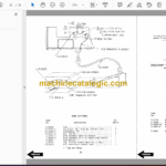
Manual Valve Wiring Diagram
Manual Control Valve Mounting/Piping
Valve Assembly
Manual Control Valve
Hydraulic Pump P-25428
Hydraulic Pump for P-25428
Motor for P-25428
Hydraulic Pump and Motor D-21421 & D-21422
Hydraulic Pump Motor for D-21421 $ D-21422
Lift Cylinder for White 3 Stage
White Masts – Three Stage
Lift Cylinder Assembly (Prime-Mover)
Prime-Mover Mast – 2 Stage
Gleason Hose Reel Assembly
Gleason Reel 35 Series
Reach Attachment
Service Guide
Back Cover