Format: PDF (Printable Document)
File Language: English
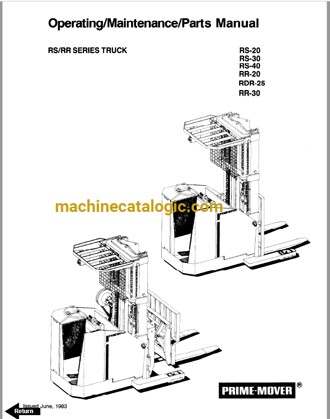
Brand: BT
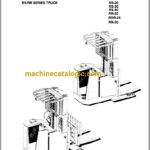
Model: RS20, RS30, RS40, RR-20, RDR25, RR30 Reach Truck
Type of Document: Maintenance, Operators and Parts Manual
$ 40
Front Cover
Warranty
New Owners
Contents
Preliminary Service
Operation Insutructions
Operating Rules and Instructions
Lubrication Chart
Maintenance Instructions
Service and Disassembly Instructions
Parts Ordering Instructions
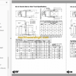
RS20 Specifications
RS30 Specifications
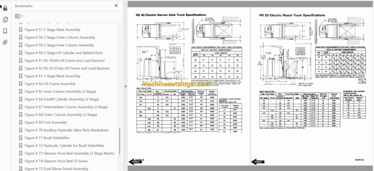
RS40 Specifications
RR20 Specifications
RR30 Specifications
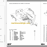
Figure # 1 Decal and Parts Assembly
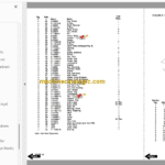
Figure # 2 Parts List and Service Reference Index
Figure # 3 Shielding Assembly
Figure # 4 Drive Mounting
Figure # 5 14:1 Transmission Assembly with MKU-4006
Drive Motor
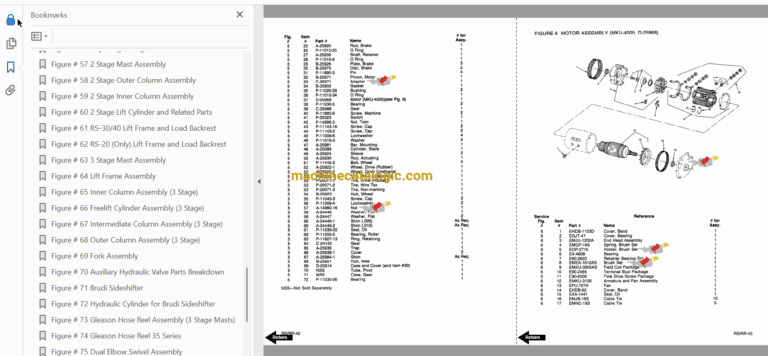
Figure # 6 Motor Assembly
Figure # 7 Brake Linkage
Figure # 8 Slave Cylinder Assembly
Figure # 9 Master Cylinder Assembly
Figure # 10 Steering Linkage
Figure # 11 Steering Assembly
Figure # 12 Power Steering Gear Box
Figure # 13 Torque Generator
Figure # 14 Forward Gear Reduction Steering Gear Box,
Reverse Chain Reduction Steering Gear Box
Figure # 15 GE Electrical Schematic – Model EV-I
Figure # 16 Electrical Schematic Symbols
Figure # 17 Wiring Harness Assembly
Figure # 18 Power Component Assembly
Figure # 19 SCR and Contactor Panel Assembly
Figure # 20 EV-I SCR Control
Figure # 21 Transformer Assembly
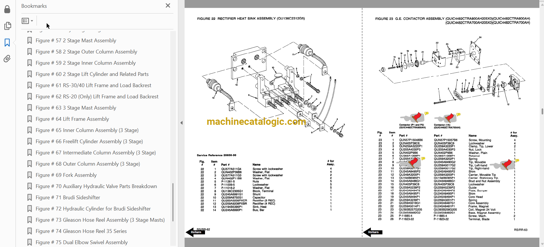
Figure # 22 Rectifier Heat Sink Assembly
Figure # 23 GE Contactor Assembly
Figure # 24 Power Steering Contactor Assembly
Figure # 25 GE Contactor Assembly
Figure # 26 Warning Light Assembly
Figure # 27 Connector Assembly
Figure # 28 Handle Assembly
Figure # 29 Master Control Switch Assembly
Figure # 30 Master Control Switch Assembly
Figure # 31 Hydraulic Schematic
Figure # 32 Hydraulic Schematic Symbols
Figure # 33 Hydraulic Assembly (2 Stage)
Figure # 34 Hydraulic Assembly – Part # 1
Figure # 35 Tilt Cylinder Assembly and Related Parts
Figure # 43 3 Stage Staging Cylinder Assembly
Figure # 44 Freelift Cylinder Assembly
Figure # 45 Hydraulic Assembly Part # 3
Figure # 46 Pump and Motor Assembly
Figure # 47 Motor Assembly
Figure # 48 Power Steering Pump Assembly
Figure # 50 Control Valve Assembly
Figure # 51 Control Valve Assembly
Figure # 52 Hydraulic Pump and Motor
Figure # 53 Pump Assembly
Figure # 54 Motor Assembly
Figure # 55 Motor Assembly
Figure # 56 Adjusting Linkage
Figure # 57 2 Stage Mast Assembly
Figure # 58 2 Stage Outer Column Assembly
Figure # 59 2 Stage Inner Column Assembly
Figure # 60 2 Stage Lift Cylinder and Related Parts
Figure # 61 RS-30/40 Lift Frame and Load Backrest
Figure # 62 RS-20 (Only) Lift Frame and Load Backrest
Figure # 63 3 Stage Mast Assembly
Figure # 64 Lift Frame Assembly
Figure # 65 Inner Column Assembly (3 Stage)
Figure # 66 Freelift Cylinder Assembly (3 Stage)
Figure # 67 Intermediate Column Assembly (3 Stage)
Figure # 68 Outer Column Assembly (3 Stage)
Figure # 69 Fork Assembly
Figure # 70 Auxiliary Hydraulic Valve Parts Breakdown
Figure # 71 Brudi Sideshifter
Figure # 72 Hydraulic Cylinder for Brudi Sideshifter
Figure # 73 Gleason Hose Reel Assembly (3 Stage Masts)
Figure # 74 Gleason Hose Reel 35 Series
Figure # 75 Dual Elbow Swivel Assembly
Figure # 76 Reach Attachment
Figure # 77 Reach Attachment
Figure # 78 Reach Attachment Hydraulic Assembly
Figure # 79 Reach Attachment Cylinder Assembly
Figure # 80 Load Wheel Assembly
Troubleshooting Hydraulic Gear Pump
Service Guide
Back Cover
