Format: PDF (Printable Document)
File Language: English
File Pages: 350
File Size: 74.07 MB (Speed Download Link)
Brand: Wacker Neuson
Model: WL32 Loader
Type of Document: Service Manual
$ 45
Contents
E Introduction
E.1 Notice on this service manual
E.2 Technical data
E.3 Tightening torques
E.4 Safety instructions
E.5 Special tools
B Operation
B.1 Overview of control elements
B.2 Indicator lights and warning lights (overview)
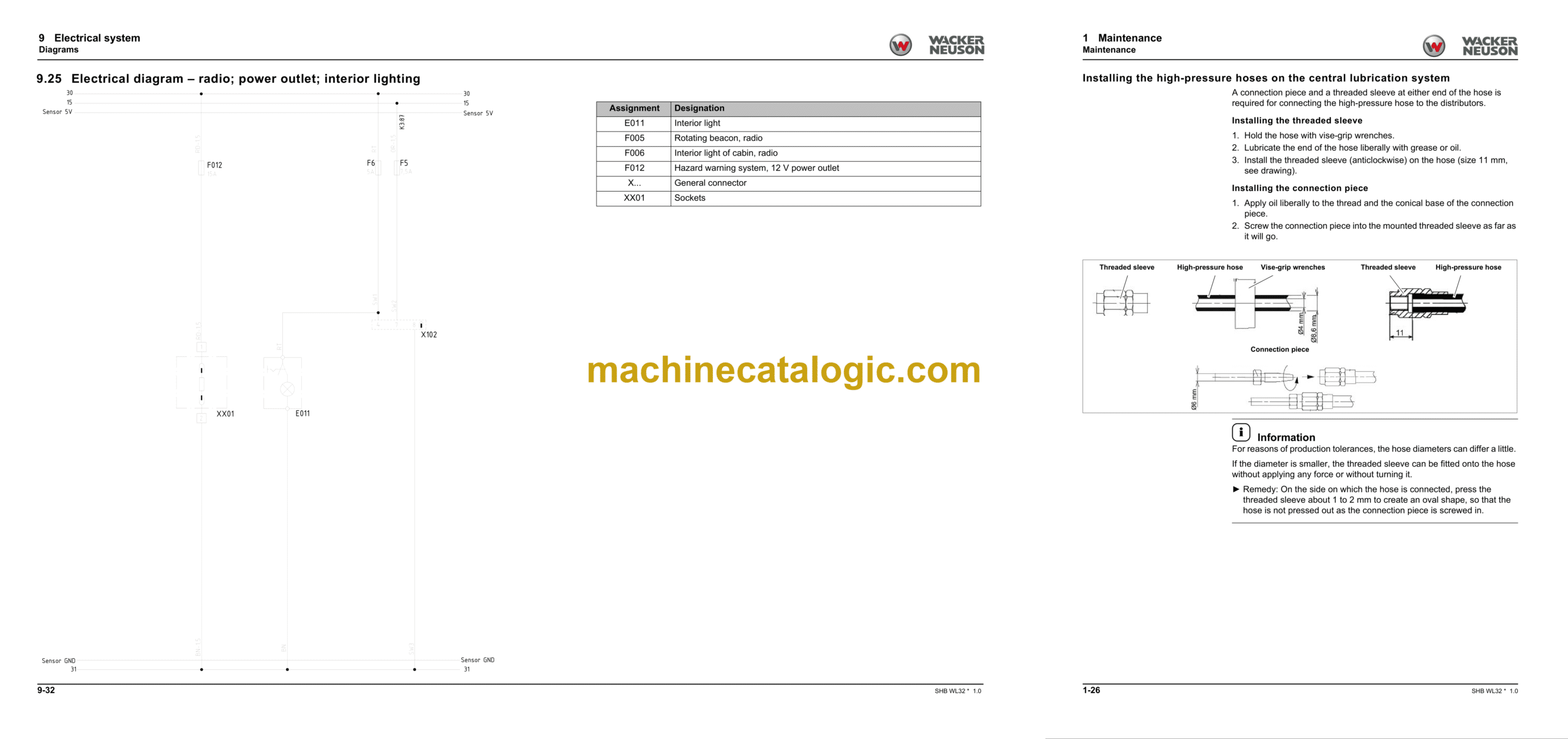
1 Maintenance
1.1 Information on maintenance
Responsibilities and prerequisites
Safety instructions
Battery master switch
1.2 Maintenance overview
Daily/weekly maintenance
Inspection schedules
Inspection intervals
1.3 Lubrication plan
1.4 Fluids and lubricants
1.5 Maintenance accesses
1.6 Cleaning and maintenance
1.7 Lubrication work
1.8 Fuel system
1.9 Engine lubrication system
1.10 Cooling system
1.11 Air filter
1.12 V-belt/toothed belt
1.13 Hydraulic system
1.14 Electrical system
1.15 Heating, ventilation and air conditioning system (option)
1.16 Washer system
1.17 Axles/traveling drive
1.18 Braking system
1.19 Tires
1.20 Maintenance and servicing work on attachments
1.21 Maintenance of options
1.22 Exhaust gas treatment
2 Engine
2.1 Complete component (36.3 kW engine)
2.2 Complete component (44.7 kW engine)
2.3 Alternator (44.7 kW)
2.4 Starter M001 (44.7 kW)
2.5 Diesel particulate filter (44.7 kW engine)
2.6 Removing/installing the fuel tank
3 Cooling
3.1 Removing/installing the coolant reservoir
3.2 Removing/installing the radiator
3.3 Removing/installing fan blades
4 Traveling drive
4.1 Traveling drive hose routing
4.2 Variable displacement pump P35
4.3 Variable displacement motor M20
4.4 Manifold
4.5 Hydraulic oil tank Z57
4.6 Removing/installing the cardan shaft
4.7 Removing/installing check valve V72
4.8 Troubleshooting
5 Axles
5.1 Front axle
5.2 Rear axle
5.3 Type label – front/rear axle
6 Brake
6.1 Removing/installing the brake pedal
6.2 Removing/installing the parking brake
6.3 Removing/installing the parking brake Bowden cable
6.4 Master brake cylinder
7 Steering system
7.1 Steering orbitrol S4
7.2 Removing/installing the steering wheel
7.3 Removing/installing the steering column
7.4 Removing/installing the steering column gas strut
7.5 Removing/installing steering cylinder A21
7.6 Checking the steering hydraulics
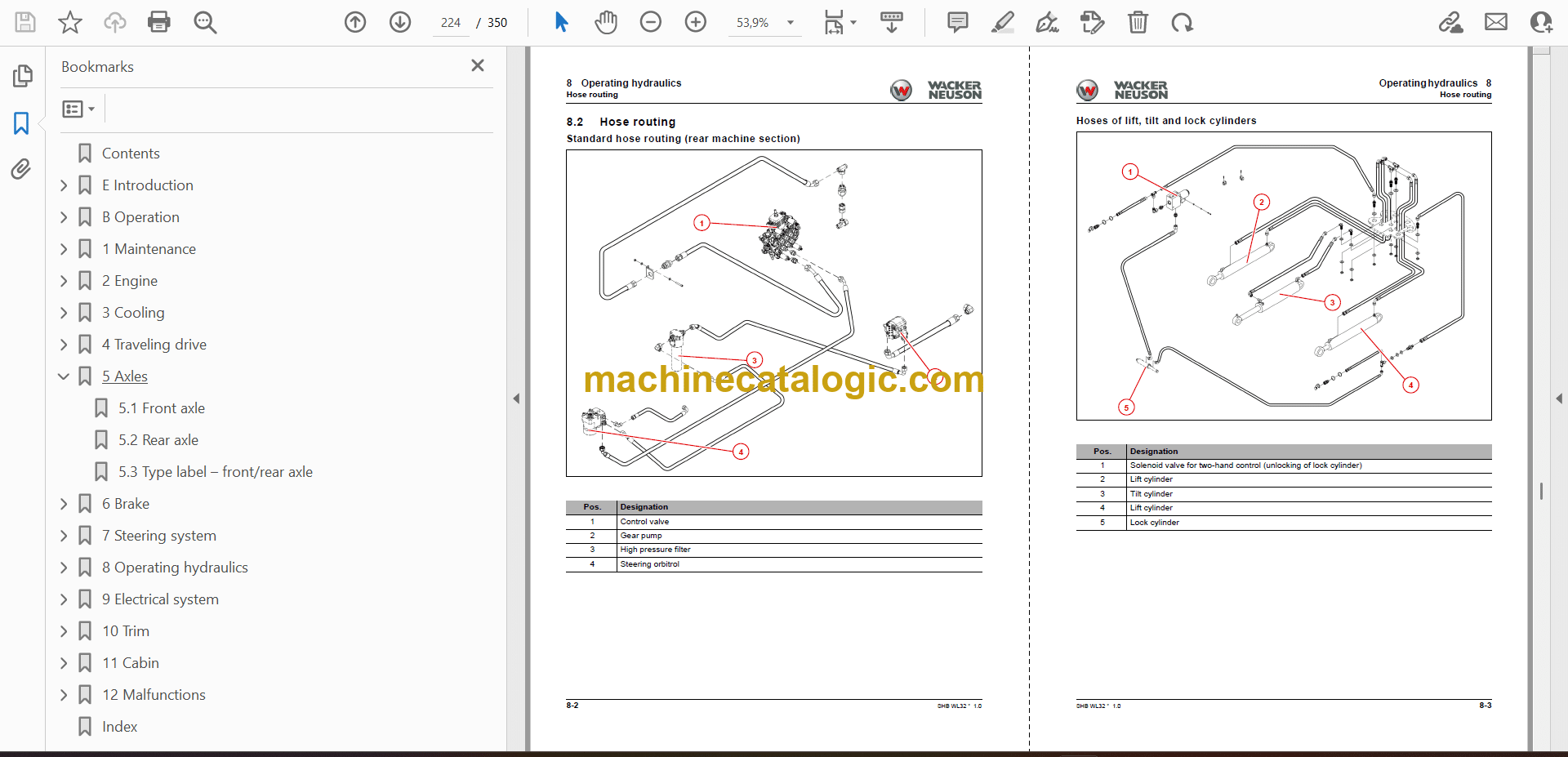
8 Operating hydraulics
8.1 Overview
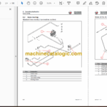
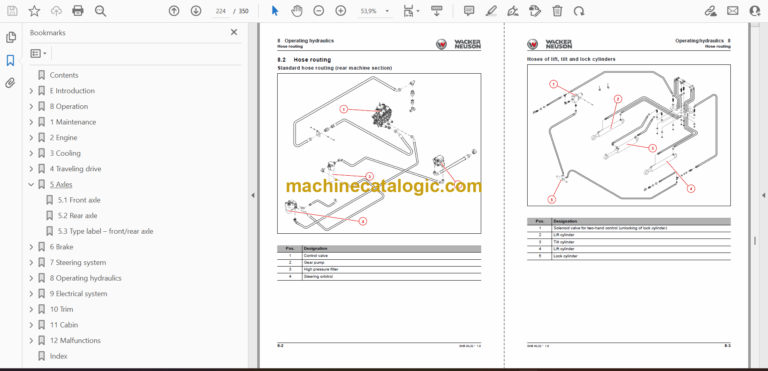
8.2 Hose routing
8.3 Gear pump P32
8.4 Removing/installing lock cylinder A4
8.5 Removing/installing the lock pin
8.6 Removing/installing the tilt cylinder
8.7 Removing/installing the loader unit
8.8 Removing/installing the lift cylinder
8.9 Removing/installing the reversing lever
8.10 Removing/installing solenoid valve V30
8.11 Removing/installing pressure relief valve V60
8.12 Removing/installing the quickhitch
8.13 Removing/installing the control valve
8.14 Designation of hydraulic components
8.15 Hydraulics diagram – HDS21/4 with HDS21/1 or 6/2 directional valve
8.16 Hydraulics diagram – HDS21/4 with HDS21/2
8.17 Hydraulics diagram – HDS21/3 with HDS21/1 or 6/2 directional valve
8.18 Hydraulics diagram – HDS21/3 with HDS21/2
8.19 Hydraulics diagram – HDS21/4 High Flow
9 Electrical system
9.1 Fuses
9.2 Removing/installing the machine control unit
9.3 Joystick
9.4 Removing/installing the battery master switch
9.5 Malfunctions of the machine electronics
9.6 Electrical diagram – power supply
9.7 Electrical diagram – control electronics power supply; joystick lighting
9.8 Electrical diagram – Perkins engine 404D-22
9.9 Electrical diagram – Perkins engine 404D-22
9.10 Electrical diagram – Perkins engine 404F-22
9.11 Electrical diagram – Perkins engine 404F-22
9.12 Electrical diagram – Ciam instrument
9.13 Electrical diagram – Bauser LED instrument
9.14 Electrical diagram – travel function
9.15 Electrical diagram – turn indicator system; horn
9.16 Electrical diagram – lights according to StVZO (German road traffic licensing regulations)
9.17 Electrical diagram – lights according to StVZO (German road traffic licensing regulations)
9.18 Electrical diagram – working lights; rotating beacon
9.19 Electrical diagram – air conditioning; seat
9.20 Electrical diagram – wiper/wash system
9.21 Electrical diagram – E connection (front & rear); Hydro Comfort; continuous operation of the 3rd control circuit
9.22 Electrical diagram – hydraulic system 1
9.23 Electrical diagram – hydraulic system 2
9.24 Electrical diagram – hydraulic system 3
9.25 Electrical diagram – radio; power outlet; interior lighting
9.26 Designation of electrical components
10 Trim
10.1 Removing/installing the engine cover
10.2 Removing/installing the floor panels
10.3 Removing/installing the trailer power outlet
10.4 Removing/installing the trailer coupling/chassis cover
10.5 Removing/installing the counterweight
11 Cabin
11.1 Removing/installing the operator seat
11.2 Removing/installing the indicating instrument
11.3 Removing/installing the starter
11.4 Removing/installing the 12 V connector
11.5 Removing/installing the control lever console
11.6 Radio
11.7 Removing/installing the armrest
11.8 Removing/installing the heating
11.9 Removing/installing the cabin
11.10 Removing/installing the base plate
12 Malfunctions
12.1 Towing a machine
12.2 Error code lists
Index

