Format: PDF (Printable Document)
File Language: English
File Pages: 438
File Size: 54.61 MB (Speed Download Link)
Brand: Wacker Neuson
Model: WL20e Wheel Loader
Type of Document: Service Manual
$ 45
Contents
E Introduction
E.1 Notice on this service manual
E.2 Technical data
E.3 Tightening torques
E.4 Safety instructions
E.5 Special tools
B Operation
B.1 Overview of control elements
1 Maintenance
1.1 Information on maintenance
1.2 Maintenance overview
1.3 Fluids and lubricants
1.4 Maintenance accesses
1.5 Cleaning and maintenance
1.6 Lubrication work
1.7 Hydraulic system
1.8 Electrical system
1.9 Exide battery
1.10 AGM battery
1.11 Axles/traveling drive
1.12 Brake system
1.13 Service brake
1.14 Parking brake
1.15 Tires
1.16 Maintenance and servicing work on attachments
1.17 Maintenance of options
1.18 Electrical control procedures according to DIN VDE 0701 / 0702
2 Engine
2.1 Hydraulic motor M030
2.2 Accelerator pedal B054
3 Traveling drive
3.1 Cardan shaft
3.2 Transfer gearbox
4 Axles
4.1 Front axle
4.2 Rear axle
5 Brakes
5.1 Brake pedal
5.2 Master brake cylinder
5.3 Parking brake
6 Steering system
6.1 Steering orbitrol S3
6.2 Steering column gas spring
6.3 Steering column
6.4 Steering cylinder A16
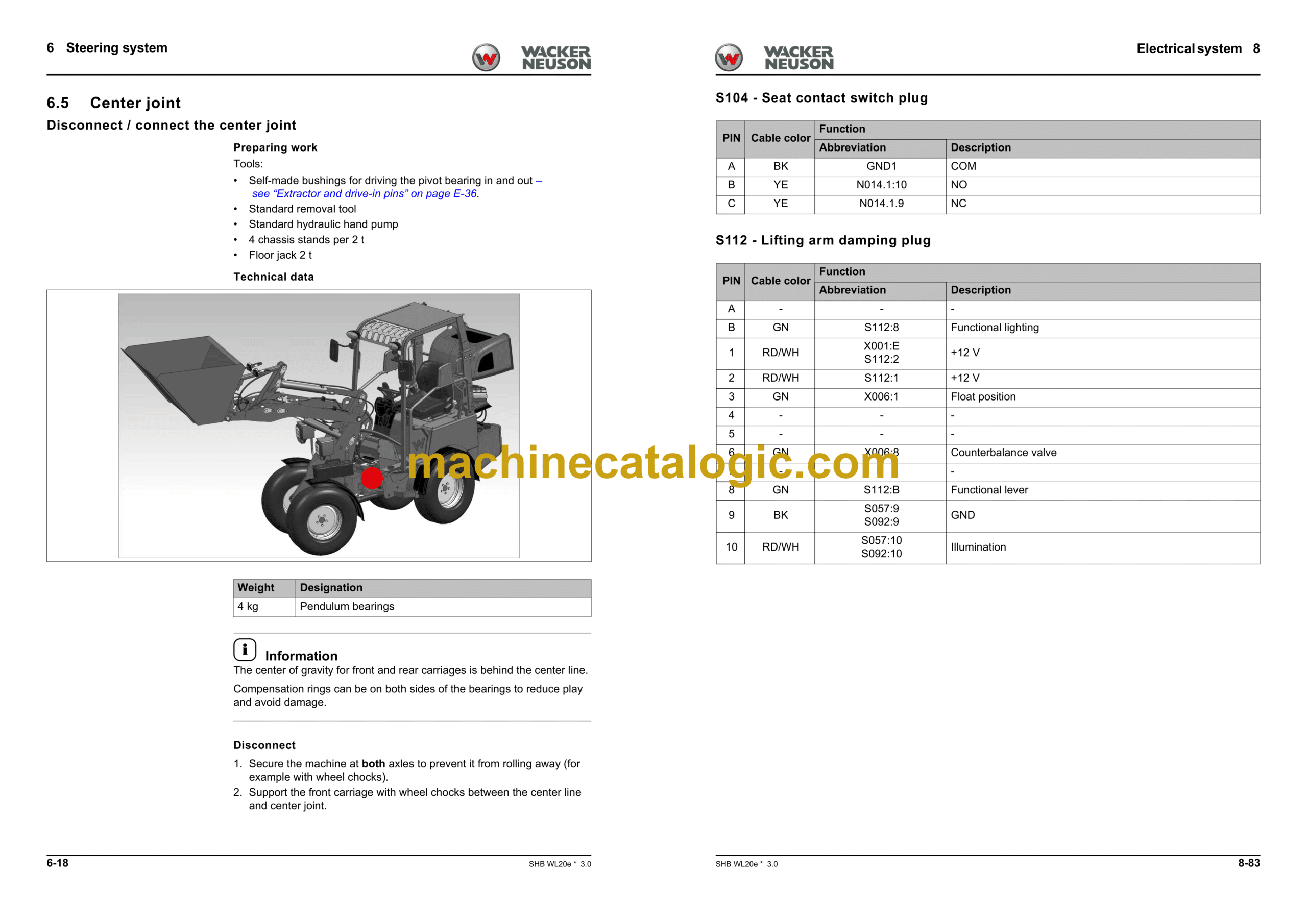
6.5 Center joint
6.6 Bearings in the pendulum bearing
6.7 Lower bearing
7 Hydraulic system
7.1 Control valve
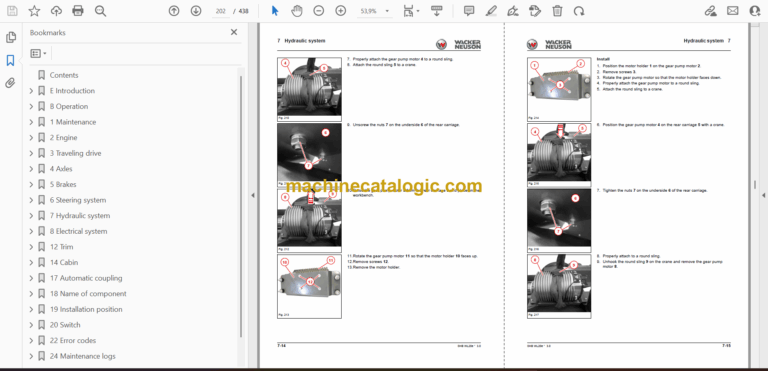
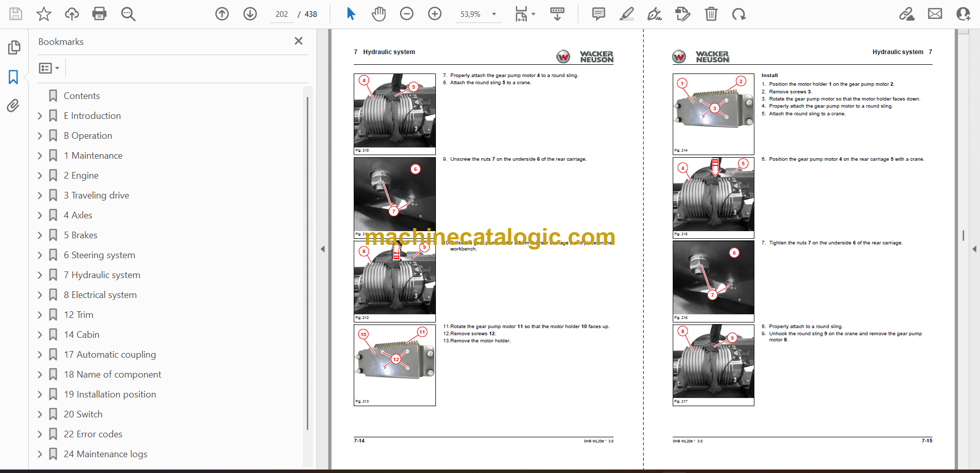
7.2 Gear pump motor M031
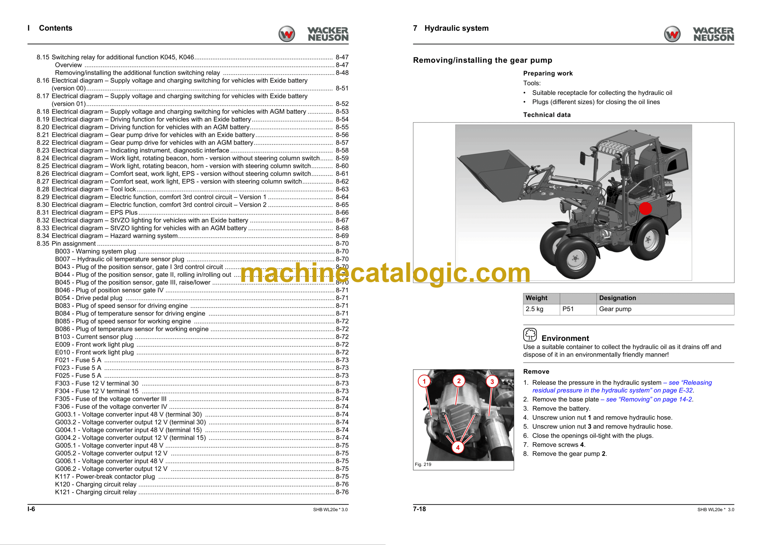
7.3 Gear pump P51
7.4 Lock cylinder A4
7.5 Lock pins
7.6 Mast
7.7 Lifting cylinder A11, A36, A37
7.8 Tilt cylinder A45, A46, A47, A48
7.9 Reversing lever
7.10 Bearings on the pull rod
7.11 Hydraulic cylinder pivot bearing
7.12 Hydraulic cylinder bearing bush
7.13 Hydraulic lines
7.14 Designation of hydraulic components
7.15 Hydraulics Diagram – Vehicle without options
7.16 Hydraulics Diagram – Vehicle with optional lock cylinder
7.17 Hydraulics Diagram – Vehicle with optional 3rd control circuit Comfort
7.18 Hydraulics Diagram – Vehicle with optional Return without pressure
7.19 Hydraulics Diagram – Vehicle with optional Floating position
7.20 Hydraulics Diagram – Vehicle with optional hydraulic cylinder with counterbalance valve
7.21 Hydraulics Diagram – Vehicle with 3rd control circuit and all possible options
7.22 Hydraulics Diagram – Vehicle with rear hydraulic connection
7.23 Hydraulics Diagram – Vehicle with 4th control circuit and all options
7.24 Hydraulics Diagram – Steering system
7.25 Hydraulics Diagram – Lift cylinder
7.26 Hydraulics Diagram – Tilt cylinder
7.27 Hydraulics Diagram – EPS Plus
7.28 Hydraulics diagram – Differential lock
8 Electrical system
8.1 Overview
8.2 Fuses, relay
8.3 Joystick
8.4 Indicating instrument P011
8.5 Main contactor K117
8.6 Secondary contactor K131
8.7 Twin inverter N030
8.8 Voltage converter G003, G004, G005
8.9 Control unit ECU N014
8.10 Headlight with blinker
8.11 Tail light with blinker
8.12 Work light E007/E009/E010
8.13 Hydraulic oil temperature sensor B007
8.14 Reverse warning system B018
8.15 Switching relay for additional function K045, K046
8.16 Electrical diagram – Supply voltage and charging switching for vehicles with Exide battery (version 00)
8.17 Electrical diagram – Supply voltage and charging switching for vehicles with Exide battery (version 01)
8.18 Electrical diagram – Supply voltage and charging switching for vehicles with AGM battery
8.19 Electrical diagram – Driving function for vehicles with an Exide battery
8.20 Electrical diagram – Driving function for vehicles with an AGM battery
8.21 Electrical diagram – Gear pump drive for vehicles with an Exide battery
8.22 Electrical diagram – Gear pump drive for vehicles with an AGM battery
8.23 Electrical diagram – Indicating instrument, diagnostic interface
8.24 Electrical diagram – Work light, rotating beacon, horn – version without steering column switch
8.25 Electrical diagram – Work light, rotating beacon, horn – version with steering column switch
8.26 Electrical diagram – Comfort seat, work light, EPS – version without steering column switch
8.27 Electrical diagram – Comfort seat, work light, EPS – version with steering column switch
8.28 Electrical diagram – Tool lock
8.29 Electrical diagram – Electric function, comfort 3rd control circuit – Version 1
8.30 Electrical diagram – Electric function, comfort 3rd control circuit – Version 2
8.31 Electrical diagram – EPS Plus
8.32 Electrical diagram – StVZO lighting for vehicles with an Exide battery
8.33 Electrical diagram – StVZO lighting for vehicles with an AGM battery
8.34 Electrical diagram – Hazard warning system
8.35 Pin assignment
8.36 Plug
12 Trim
12.1 Engine cover
12.2 Back-up stop pad
12.3 Tailgate
12.4 Cover box
12.5 Front mudguard
12.6 Steering column cover plate
12.7 Rear mudguard
14 Cabin
14.1 Base plate
14.2 Operator’s seat
14.3 Seat belt
14.4 Operator’s canopy
14.5 Seat belt buckle
14.6 Armrest
14.7 Fold-down operator’s canopy
14.8 Restraining bars
14.9 Steering wheel
14.10 Document box
17 Automatic coupling
17.1 Self-securing coupling
18 Name of component
18.1 Designation of electrical components
19 Installation position
19.1 Hydraulic system
19.2 Electrical system
20 Switch
20.1 Overview of switch assignment
22 Error codes
22.1 Error code table
24 Maintenance logs
24.1 Grounded conductor / insulation resistance measurement
24.2 Measurement at the battery cells
Index


