Format: PDF (Printable Document)
File Language: English
File Pages: 1048
File Size: 53.49 MB (Speed Download Link)
Brand: Wacker Neuson
Model: 4507, KT457 5007, KT507, 5507, KT557, 4209, KT429, 5509, KT559 Telehandlers
Type of Document: System Manual
$ 45
System manual
E Introduction
E.1 Notes on system manual
E.2 Safety instructions
E.3 Symbol and abbreviations
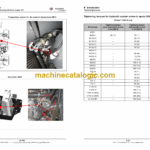
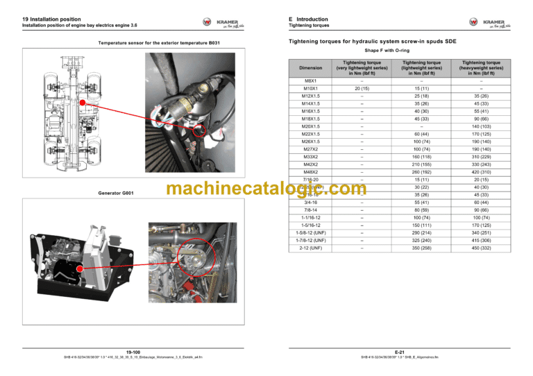
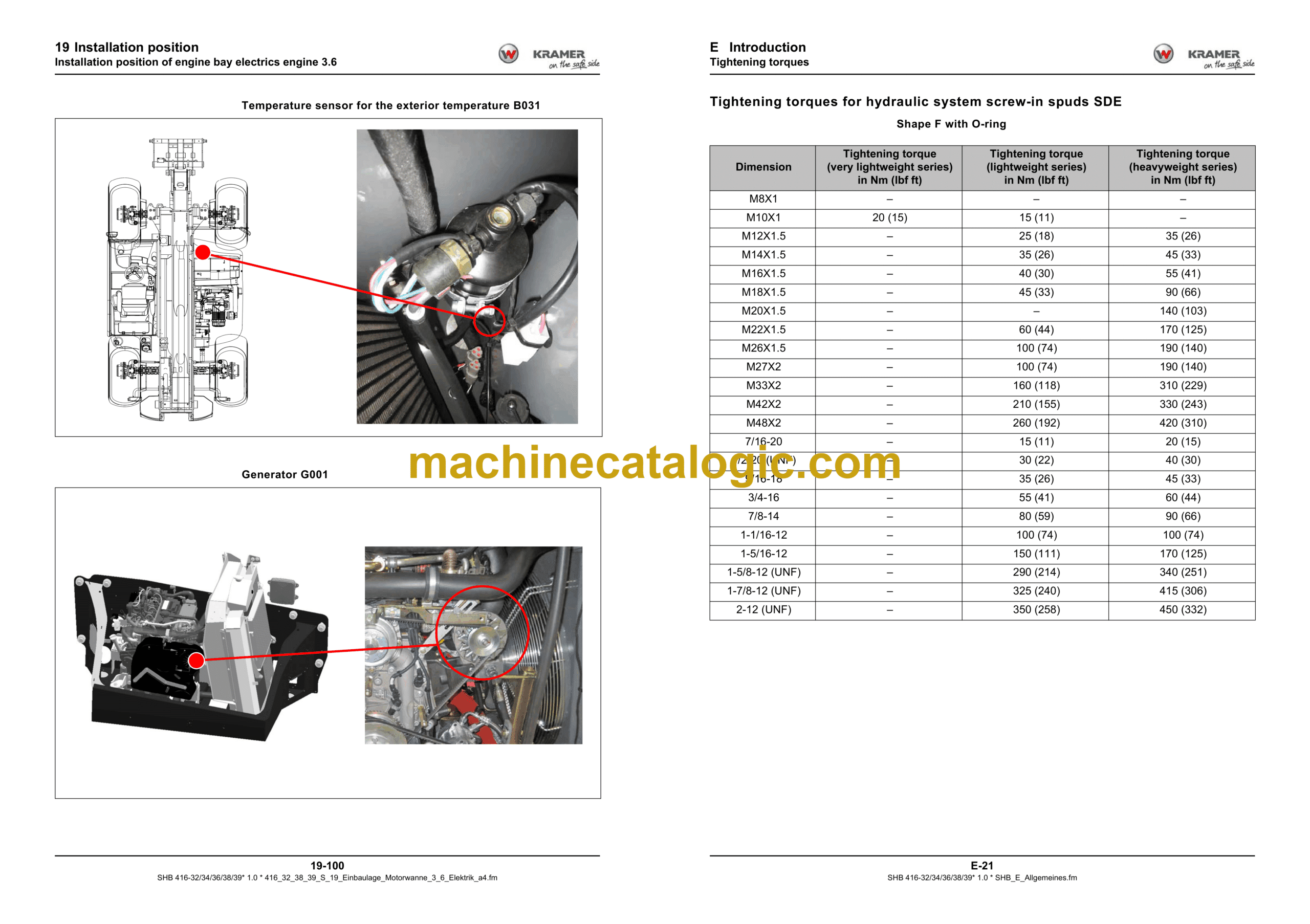
E.4 Tightening torques
2 Engine
2.1 Overview of components TCD 3.6
2.2 Lubricant oil system TCD 3.6
2.3 Fuel system TCD 3.6
2.4 Cooling system TCD 3.6
2.5 Turbocharging TCD 3.6
2.6 Exhaust gas recirculation EGR TCD 3.6
2.7 Electric components TCD 3.6
2.8 Overview of components TCD 4.1
2.9 Lubricant oil system TCD 4.1
2.10 Fuel system TCD 4.1
2.11 Cooling circuit TCD 4.1
2.12 Turbocharging TCD4.1
2.13 Exhaust gas recirculation EGR TCD 4.1
2.14 Electric components TCD 4.1
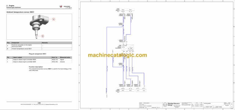
2.15 Exhaust-gas treatment
2.16 Exhaust system only for EDG
2.17 Starting the engine
2.18 Diesel engine monitoring
2.19 Diesel engine monitoring components
2.20 Control of EAT system
2.21 Heating circuit of EAT system
3 Cooling
3.1 Cooling control
3.2 Components of the component control
3.3 Functional description of cooling components
3.4 Cooling component description
3.5 Check / adjust cooling
4 Traveling drive
4.1 Drive control
4.2 Function description of travelling drive
4.3 Drive component description
4.4 Drive system with H1P and ICVD
4.5 Checking / adjusting ICVD high speed gearbox
4.6 Error descriptions
4.7 Drive system with H1P and P370
4.8 Adjustment work for drive system
4.9 Error descriptions
6 Brakes
6.1 Brake control
6.2 Trailer compressed air brake control
6.3 Functional description of the braking system components
6.4 Description of brake system elements
6.5 Element description for the compressed air system
6.6 Braking system test logs
6.7 Trailer brake test log
6.8 Compressed air brake system test log
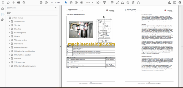
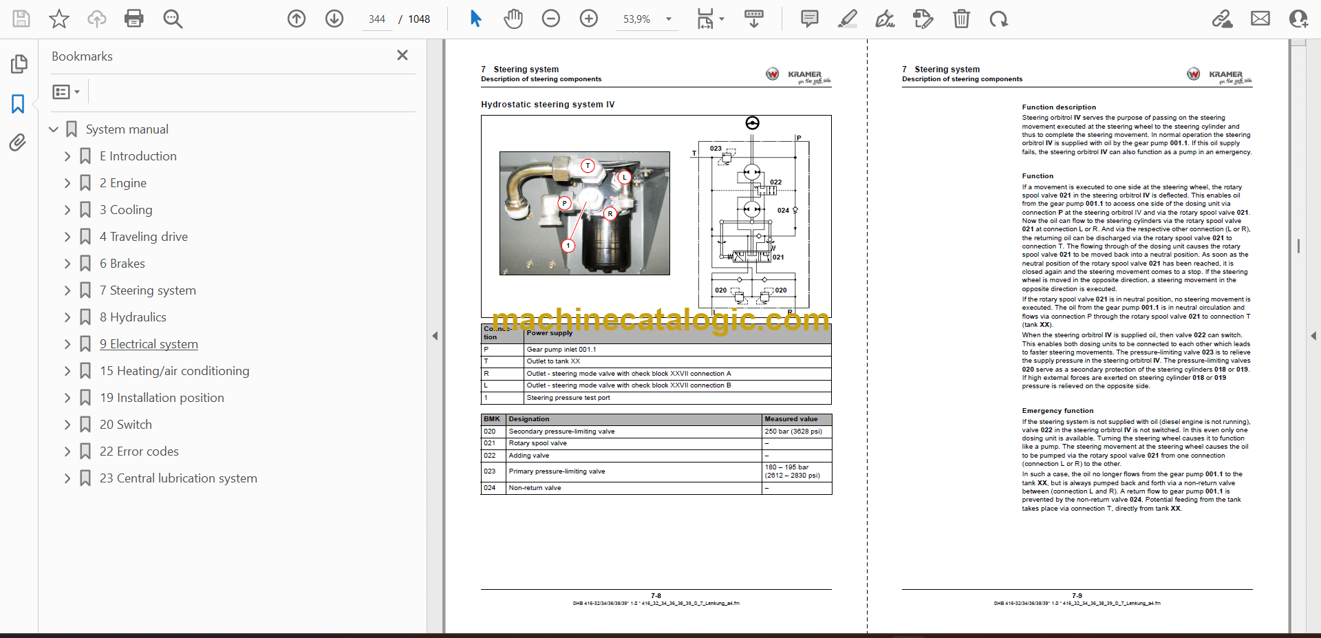
7 Steering system
7.1 Steering system actuation
7.2 Function description: steering system
7.3 Description of steering components
7.4 Check / adjust steering system
8 Hydraulics
8.1 Lifting cylinder / load stabilizer actuation
8.2 Control of the overload control
8.3 Tilt ram control
8.4 Bucket repositioning control
8.5 3rd control circuit (control)
8.6 Control of the 3rd control circuit with changeover valve
8.7 Tipper control
8.8 Control of the tipper/auto-hitch
8.9 Adjust the sensor plate sensor S137
8.10 Rear additional control circuit actuation
8.11 Actuation of additional control circuit, large, front
8.12 Control of the leveling/oscillating-axle interlock model 416-36
8.13 Control of the leveling and tipper model 416-36
8.14 Control of the leveling, tipper, hitch model 416-36
8.15 Hydraulics component description
8.16 Check / adjust work hydraulics
8.17 Checking secondary valves
8.18 Hydraulic diagrams
9 Electrical system
9.1 CAN signals component overview
9.2 Inputs/outputs for traction electronics N001
9.3 Frame controller N004 inputs / outputs
9.4 Inputs/outputs for diesel engine electronics N005
9.5 Controller N015 for cab inputs/outputs
9.6 Inputs/outputs for additional controller N016
9.7 Telematic module N018 inputs/outputs
9.8 Drive interlock N021 inputs/outputs
9.9 Oil volume setting N023 inputs/outputs
9.10 Inputs/outputs for steering electronics D001
9.11 Display P014 inputs/outputs
9.12 Fuses, relay
9.13 Safe load indicator in the display P014
9.14 Calibrating the safe load indicator
9.15 Basic setting of the travel sensor B028
9.16 Camera (front)
9.17 Rear camera
9.18 Functional descriptions of electric components
9.19 Diagrams
15 Heating/air conditioning
15.1 Control of heating, air conditioning
15.2 Safety instructions for the air-conditioning system
19 Installation position
19.1 Hydraulics
19.2 Installation position of electrical system, cab
19.3 Installation position of electrical system, frame
19.4 Installation position of engine bay electrics engine 3.6
19.5 Installation position of engine bay electrics engine 4.1
19.6 Installation position of the compressed air system
20 Switch
20.1 Switch assignment with symbols and installation location
22 Error codes
22.1 Error code list
23 Central lubrication system
23.1 Central lubrication system