Format: PDF (Printable Document)
File Language: English
File Pages: 385
File Size: 30.74 MB (Speed Download Link)
Brand: Wacker Neuson
Model: 6503 Mobile Excavator
Type of Document: Service Manual
$ 45
Operation
Important information on this service manual …………………………………………………. 1-1
Identification of warnings and dangers ………………………………………………………….. 1-2
Designated use and exemption from liability ………………………………………………….. 1-3
Type labels and component numbers ……………………………………………………………. 1-4
Machine overview ………………………………………………………………………………………. 1-6
Cab overview …………………………………………………………………………………………….. 1-7
Up to serial no. AD07227 ………………………………………………………………………. 1-7
From serial no. AH00708 ……………………………………………………………………….. 1-8
Cab (legend) ……………………………………………………………………………………………… 1-9
Instrument panel overview …………………………………………………………………………. 1-10
Up to serial no. AD07227 …………………………………………………………………….. 1-10
From serial no. AH00708 ……………………………………………………………………… 1-11
Instrument panel (legend) ………………………………………………………………………….. 1-12
Engine compartment overview up to serial no. AD07227 ……………………………….. 1-13
Engine compartment overview from serial no. AH00708 ………………………………… 1-14
Chassis overview ……………………………………………………………………………………… 1-15
Tilting the cab ………………………………………………………………………………………….. 1-16
Summer/winter operation …………………………………………………………………………… 1-18
Pedal for auxiliary hydraulics/swivelling and rotating the boom ……………………….. 1-19
Battery master switch ……………………………………………………………………………….. 1-19
Specifications
Chassis …………………………………………………………………………………………………….. 2-1
Engine ………………………………………………………………………………………………………. 2-1
Fuel injection pump ………………………………………………………………………………. 2-3
Capacities ……………………………………………………………………………………………. 2-3
Tightening torques ………………………………………………………………………………… 2-3
Hydraulic system ……………………………………………………………………………………….. 2-4
Auxiliary hydraulics oil flow* …………………………………………………………………… 2-5
Screwable hose burst valve ……………………………………………………………………. 2-5
Undercarriage and swivel unit ……………………………………………………………………… 2-5
Stabiliser blade ………………………………………………………………………………………….. 2-5
Electric system …………………………………………………………………………………………… 2-5
Fuse box in instrument panel (up to AD07227) …………………………………………. 2-6
Main fuse box with relays under the cab (up to AD07227) ………………………….. 2-6
Relays up to serial no. AD07227 …………………………………………………………….. 2-7
Fuse box in instrument panel (from AH00708) ………………………………………….. 2-7
Main fuse box with relays from serial no. AH00708 …………………………………… 2-8
Noise levels ………………………………………………………………………………………………. 2-8
Vibration ……………………………………………………………………………………………………. 2-8
Coolant compound table ……………………………………………………………………………… 2-8
Tyres ………………………………………………………………………………………………………… 2-9
Model-specific tightening torques …………………………………………………………………. 2-9
General tightening torques ………………………………………………………………………….. 2-9
Tightening torques for hydraulic screw connections (dry assembly) …………….. 2-9
Tightening torques for high-resistance screw connections ………………………… 2-11
Dimensions model 6503 ……………………………………………………………………………. 2-12
Dimensions model 6503 WD with triple articulation boom (option) ………………….. 2-13
Lift capacity table 6503 WD ……………………………………………………………………….. 2-15
Lift capacity table 6503 with twin tyres (option) …………………………………………….. 2-16
Lift capacity table 6503 with triple articulation boom (option) ………………………….. 2-17
Lift capacity table 6503 with twin tyres (option) and triple articulation boom (option) ….
Lift capacity table 6503 with long stick (option) ……………………………………………… 2-19
Lift capacity table 6503 with long stick (option) and twin tyres (option) …………….. 2-20
Lift capacity table 6503 with long stick (option) and triple articulation boom (option) ….
2-21
Lift capacity table 6503 with long stick (option), twin tyres (option) and triple articulation
boom (option) …………………………………………………………………………………………… 2-22
Kinematics ………………………………………………………………………………………………. 2-23
Attachments …………………………………………………………………………………………….. 2-23
Maintenance
Fluids and lubricants …………………………………………………………………………………… 3-1
Additional oil change and filter replacement (hydraulics) ……………………………. 3-2
Maintenance label ………………………………………………………………………………………. 3-3
Explanation of symbols on the maintenance label ……………………………………… 3-3
Maintenance plan (overview) ……………………………………………………………………….. 3-5
Service package ………………………………………………………………………………………… 3-9
Up to serial no. AD07227 ……………………………………………………………………….. 3-9
From serial no. AH00708 ……………………………………………………………………….. 3-9
Introduction ……………………………………………………………………………………………….. 3-9
Fuel system ……………………………………………………………………………………………… 3-10
Specific safety instructions …………………………………………………………………… 3-10
Refuelling …………………………………………………………………………………………… 3-10
Stationary fuel pumps ………………………………………………………………………….. 3-11
Diesel fuel specification ……………………………………………………………………….. 3-11
Bleeding the fuel system ………………………………………………………………………. 3-11
Emptying the fuel tank …………………………………………………………………………. 3-12
Fuel prefilter with water separator …………………………………………………………. 3-12
Replacing the fuel filter ………………………………………………………………………… 3-13
Engine lubrication system ………………………………………………………………………….. 3-14
Checking the oil level …………………………………………………………………………… 3-14
Filling up engine oil ……………………………………………………………………………… 3-15
Changing engine oil …………………………………………………………………………….. 3-16
Replacing the engine oil filter cartridge …………………………………………………… 3-17
Cooling system ………………………………………………………………………………………… 3-18
Specific safety instructions …………………………………………………………………… 3-18
Checking/filling up coolant ……………………………………………………………………. 3-19
Draining coolant ………………………………………………………………………………….. 3-20
Air filter ……………………………………………………………………………………………………. 3-21
Replacing the filter ………………………………………………………………………………. 3-22
Functional check once a week of the dust valve ……………………………………… 3-23
V-belt ………………………………………………………………………………………………………. 3-24
Checking V-belt tension ……………………………………………………………………….. 3-24
Retightening the V-belt ………………………………………………………………………… 3-25
Checking the V-belt of the air conditioning system …………………………………… 3-26
Tightening the V-belt of the air conditioning system …………………………………. 3-26
Pressure check ………………………………………………………………………………………… 3-27
General ……………………………………………………………………………………………… 3-27
Checking pilot control pressure …………………………………………………………….. 3-27
Pressure check of variable displacement pump P1 ………………………………….. 3-28
Pressure check of variable displacement pump P2 ………………………………….. 3-29
Pressure check of gear pump P3 ………………………………………………………….. 3-30
Secondary pressure limiting valve of the gear motor ………………………………… 3-31
Measuring ports: overview ……………………………………………………………………. 3-31
Primary pressure limiting valves ……………………………………………………………. 3-31
SERV-HB 6503 EN – Edition 2.0 * 6503s11IVZ.fm I-3
table of contents
Test report ………………………………………………………………………………………………. 3-32
Hydraulic system ……………………………………………………………………………………… 3-34
Specific safety instructions …………………………………………………………………… 3-34
…………………………………………………………………………………………………………. 3-34
Checking the hydraulic oil level …………………………………………………………….. 3-35
Filling up hydraulic oil ………………………………………………………………………….. 3-36
Replacing hydraulic oil …………………………………………………………………………. 3-37
Monitoring the hydraulic oil reflux filter …………………………………………………… 3-37
Checking hydraulic pressure lines …………………………………………………………. 3-38
Lubrication work ……………………………………………………………………………………….. 3-39
Stabiliser blade …………………………………………………………………………………… 3-39
Lubrication points on the swivelling console ……………………………………………. 3-39
Boom lubrication points ……………………………………………………………………….. 3-40
Lubrication points on the stick ………………………………………………………………. 3-40
Lubrication strip ………………………………………………………………………………….. 3-41
Ring gear …………………………………………………………………………………………… 3-41
Maintenance of attachments ………………………………………………………………… 3-41
Electric system …………………………………………………………………………………………. 3-42
Specific safety instructions …………………………………………………………………… 3-42
Service and maintenance work at regular intervals ………………………………….. 3-42
Instructions concerning specific components ………………………………………….. 3-43
Alternator …………………………………………………………………………………………… 3-43
Battery ………………………………………………………………………………………………. 3-44
Jump-starting the engine ……………………………………………………………………… 3-44
Cab ………………………………………………………………………………………………………… 3-45
Replacing the cab filter ………………………………………………………………………… 3-45
General maintenance work ………………………………………………………………………… 3-46
Cleaning ……………………………………………………………………………………………. 3-46
General instructions for all areas of the machine …………………………………….. 3-46
Inside the cab …………………………………………………………………………………….. 3-47
Exterior of the machine ………………………………………………………………………… 3-47
Engine compartment …………………………………………………………………………… 3-48
Screw connections and attachments ……………………………………………………… 3-48
Pivots and hinges ……………………………………………………………………………….. 3-48
Engine
Engine 4TNV98-VNS (American Tier 2 up to serial no. AD07227) ……………………. 4-1
Fuel system ………………………………………………………………………………………………. 4-3
Removing the valve cover …………………………………………………………………………… 4-4
Checking and adjusting valve clearance ……………………………………………………….. 4-4
Checking valve clearance ………………………………………………………………………. 4-4
Setting zero play of the valve bridge ……………………………………………………….. 4-5
Setting valve clearance …………………………………………………………………………. 4-5
Tightening order for cylinder head bolts ………………………………………………………… 4-6
Checking the injection nozzles …………………………………………………………………….. 4-7
Pressure check …………………………………………………………………………………….. 4-7
Checking the nozzle jet ……………………………………………………………………………….. 4-7
Injection time ……………………………………………………………………………………………… 4-8
Checking injection time ………………………………………………………………………….. 4-8
Setting injection time …………………………………………………………………………….. 4-9
Replacement of fuel injection pump ………………………………………………………… 4-9
Adjusting engine revs ………………………………………………………………………………… 4-11
Compression ……………………………………………………………………………………………. 4-11
Checking the coolant thermostat ………………………………………………………………… 4-12
Checking the thermal switch ………………………………………………………………………. 4-12
Oil pressure switch ……………………………………………………………………………………. 4-13
Checking the coolant circuit ……………………………………………………………………….. 4-13
Engine 4TNV98-ZVNS from serial no. AH00708 ………………………………………….. 4-14
Fuel system ……………………………………………………………………………………………… 4-16
Removing the valve cover ………………………………………………………………………….. 4-17
Checking and adjusting valve clearance ………………………………………………………. 4-17
Checking valve clearance …………………………………………………………………….. 4-17
Setting zero play of the valve bridge ………………………………………………………. 4-18
Setting valve clearance ………………………………………………………………………… 4-18
Tightening order for cylinder head bolts ……………………………………………………….. 4-19
Checking the injection nozzles ……………………………………………………………………. 4-20
Pressure check …………………………………………………………………………………… 4-20
Checking the nozzle jet ……………………………………………………………………………… 4-20
Injection time ……………………………………………………………………………………………. 4-21
Checking injection time ………………………………………………………………………… 4-21
Setting injection time ……………………………………………………………………………. 4-22
Replacement of fuel injection pump ……………………………………………………….. 4-23
Compression ……………………………………………………………………………………………. 4-24
Checking the coolant thermostat ………………………………………………………………… 4-24
Checking the thermal switch ………………………………………………………………………. 4-25
Oil pressure switch ……………………………………………………………………………………. 4-25
Checking the coolant circuit ……………………………………………………………………….. 4-25
Engine trouble ………………………………………………………………………………………….. 4-26
Electronic engine control (E-ECU) ………………………………………………………………. 4-28
Features …………………………………………………………………………………………….. 4-28
Engine error codes ……………………………………………………………………………………. 4-29
Error diagnosis …………………………………………………………………………………………. 4-33
E-ECU connector assignment ………………………………………………………………. 4-33
Important information on the ECU maintenance wiring harness ………………… 4-34
Flash code 7 – proportional injection pump solenoid (control rack) …………….. 4-35
Related DTC (Diagnostic Trouble Codes) ………………………………………………. 4-35
Diagnosis description …………………………………………………………………………… 4-37
Flash code 5 – manual throttle ……………………………………………………………… 4-39
Related DTC ………………………………………………………………………………………. 4-39
Work description …………………………………………………………………………………. 4-41
Flash code 4-1 ECU internal …………………………………………………………………. 4-42
Related DTC ………………………………………………………………………………………. 4-42
Work description …………………………………………………………………………………. 4-43
Flash code 4-1 ECU temperature sensor and 2-5 ECU temperature rise alarm …..
4-44
Related DTC ………………………………………………………………………………………. 4-44
Work description …………………………………………………………………………………. 4-45
Flash code 4 coolant temperature sensor and 3-6 coolant temperature rise alarm
4-46
Related DTC ………………………………………………………………………………………. 4-46
Work description …………………………………………………………………………………. 4-48
Flash code 2-4 – sensor 5 V …………………………………………………………………. 4-50
Related DTC ………………………………………………………………………………………. 4-50
Work description …………………………………………………………………………………. 4-51
Flash code 2-3 – power supply voltage ………………………………………………….. 4-53
(1) P0562/1: power supply voltage error (voltage too low) ………………………… 4-53
DTC detection conditions ……………………………………………………………………… 4-53
Troubleshooting ………………………………………………………………………………….. 4-53
SERV-HB 6503 EN – Edition 2.0 * 6503s11IVZ.fm I-5
table of contents
Diagnosis description ………………………………………………………………………….. 4-53
(2) P0563/0: power supply voltage error (voltage too high) ……………………….. 4-54
DTC detection conditions …………………………………………………………………….. 4-54
Troubleshooting ………………………………………………………………………………….. 4-54
Diagnosis description ………………………………………………………………………….. 4-54
Flash code 6 – revs sensor ………………………………………………………………….. 4-55
Work description …………………………………………………………………………………. 4-57
Flash code 1-1 – backup revs sensor …………………………………………………….. 4-58
Related DTC ………………………………………………………………………………………. 4-58
Work description …………………………………………………………………………………. 4-60
Flash code 9 – overspeed error …………………………………………………………….. 4-61
(1) P0219/0: overspeed error ……………………………………………………………….. 4-61
DTC detection conditions …………………………………………………………………….. 4-61
Troubleshooting ………………………………………………………………………………….. 4-61
Diagnosis description ………………………………………………………………………….. 4-61
Flash code 1-7 – proportional solenoid relay of the injection pump (control rack) ..
4-62
Related DTC ………………………………………………………………………………………. 4-62
Work description …………………………………………………………………………………. 4-64
Flash code 1-5 – preheating relay …………………………………………………………. 4-66
Related DTC ………………………………………………………………………………………. 4-66
Work description …………………………………………………………………………………. 4-67
Flash code 1-4 – CSD (cold start device) solenoid coil …………………………….. 4-70
Related DTC ………………………………………………………………………………………. 4-70
Work description …………………………………………………………………………………. 4-71
Flash code 1-3 – EGR (exhaust gas recirculation) valve ………………………….. 4-73
Related DTC ………………………………………………………………………………………. 4-73
Work description …………………………………………………………………………………. 4-75
Flash code 2-1 – oil pressure switch and 3-1 – oil pressure drop error ……….. 4-77
Related DTC ………………………………………………………………………………………. 4-77
Work description …………………………………………………………………………………. 4-79
Flash code 8 – proportional injection pump solenoid (control rack) ……………. 4-81
Related DTC ………………………………………………………………………………………. 4-81
Work description …………………………………………………………………………………. 4-83
Flash code 1-6 – main relay …………………………………………………………………. 4-85
Related DTC ………………………………………………………………………………………. 4-85
Work description …………………………………………………………………………………. 4-87
Flash code 1-2 – CAN (Controller Area Network) communication ……………… 4-89
Related DTC ………………………………………………………………………………………. 4-89
Work description …………………………………………………………………………………. 4-90
Automatic revs setting ………………………………………………………………………………. 4-91
How it works ………………………………………………………………………………………. 4-91
Undercarriage
Hydraulic motor ………………………………………………………………………………………….. 5-1
Hydraulic motor diagram ……………………………………………………………………….. 5-2
Travelling drive ………………………………………………………………………………………….. 5-3
Steering axle ……………………………………………………………………………………………… 5-4
Oil change …………………………………………………………………………………………………. 5-5
Lubrication ………………………………………………………………………………………………… 5-5
Checks ……………………………………………………………………………………………………… 5-6
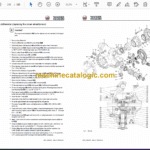
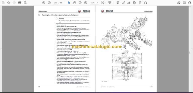
Replacing the differential …………………………………………………………………………….. 5-7
Repairing the differential (replacing the crown wheel/pinion) ……………………………. 5-9
Determining the thickness of the spacer (4/11) …………………………………………….. 5-11
Spacer ………………………………………………………………………………………………. 5-11
Determining the thickness of the spacer (4/36) (setting the contact pattern) ……… 5-12
Adjusting the pinion bearing ……………………………………………………………………….. 5-12
Adjusting the crown wheel bearing ……………………………………………………………… 5-12
Checking the contact pattern ……………………………………………………………………… 5-12
Replacing the differential case ……………………………………………………………………. 5-14
Planetary cage …………………………………………………………………………………………. 5-15
Replacing the complete planetary cage ……………………………………………………….. 5-16
Replacing the sun gear shaft ……………………………………………………………………… 5-16
Replacing the planetary gears ……………………………………………………………………. 5-16
Replacing planetary pins ……………………………………………………………………………. 5-17
Replacing the ring gear carrier ……………………………………………………………………. 5-17
Replacing the wheel bearings …………………………………………………………………….. 5-18
Adjusting the wheel bearings ……………………………………………………………………… 5-18
Replacing the double cardan shaft ……………………………………………………………… 5-19
Replacing the bearing sleeves ……………………………………………………………………. 5-20
Installing kingpins ……………………………………………………………………………………… 5-21
Determining the thickness of the bearing washers ………………………………………… 5-22
Replacing the steering ram ………………………………………………………………………… 5-23
Replacing the track rod ……………………………………………………………………………… 5-23
Adjusting the track ……………………………………………………………………………………. 5-24
Friction readjustment ………………………………………………………………………………… 5-24
Replacing brake shoes ……………………………………………………………………………… 5-25
Replacing a complete wheel cylinder …………………………………………………………… 5-26
Rigid planetary axle ………………………………………………………………………………….. 5-27
Transfer gearbox Vg1 ……………………………………………………………………………….. 5-29
Oil change ……………………………………………………………………………………………….. 5-29
Replacing the rotary shaft lip seals on the cardan flange (hydraulic motor side) … 5-31
Replacing the rotary shaft lip seals on the cardan flange (brake side) ……………… 5-31
Replacing the drive pinion and the bearing …………………………………………………… 5-32
Replacing the wheel unit and the bearings …………………………………………………… 5-33
Replacing spur gears and bearings …………………………………………………………….. 5-34
Replacing the switch cylinder ……………………………………………………………………… 5-35
Replacing the gearshift shaft, the shift fork and the sliding sleeve …………………… 5-35
Replacing the brake drum ………………………………………………………………………….. 5-36
Replacing brake shoes ……………………………………………………………………………… 5-36
Parking brake/oscillating axle interlock ………………………………………………………… 5-38
Oscillating axle check valve ……………………………………………………………………….. 5-39
Tyres ………………………………………………………………………………………………………. 5-40
Inspection work …………………………………………………………………………………… 5-40
Wheel change …………………………………………………………………………………….. 5-40
Hydraulic system
Hydraulic pump PVD-3B-56P-21G5-4626F ……………………………………………………. 6-1
Pump unit: exploded view ………………………………………………………………………. 6-3
Pilot oil supply unit ………………………………………………………………………………… 6-4
Main valve block with 3rd control circuit and triple articulation boom …………………. 6-5
Ports …………………………………………………………………………………………………… 6-5
Pressure limiting valves …………………………………………………………………………. 6-6
Pump assignment …………………………………………………………………………………. 6-7
Drive counterbalancing system …………………………………………………………………….. 6-8
Pump assignment for drive counterbalancing ……………………………………………. 6-8
Drive counterbalancing diagram ……………………………………………………………… 6-9
SERV-HB 6503 EN – Edition 2.0 * 6503s11IVZ.fm I-7
table of contents
Regeneration – stick section ………………………………………………………………………. 6-10
Bucket pre-tension ……………………………………………………………………………………. 6-10
Boom raise summation ……………………………………………………………………………… 6-11
Check valve (load retaining valve) ………………………………………………………………. 6-12
Flow rate adjustment of auxiliary hydraulics …………………………………………………. 6-13
Pilot valves ………………………………………………………………………………………………. 6-14
Joystick ……………………………………………………………………………………………… 6-14
Joystick legend …………………………………………………………………………………… 6-15
Pilot valve (driving) ……………………………………………………………………………… 6-16
Pilot valve for auxiliary hydraulics ………………………………………………………….. 6-17
Steering unit ………………………………………………………………………………………. 6-18
Steering system and priority valve …………………………………………………………. 6-20
Valves …………………………………………………………………………………………………….. 6-21
7/2 directional valve (changeover valve) ………………………………………………… 6-21
Shuttle valve block ………………………………………………………………………………. 6-22
Changeover valve for SAE/ISO controls (option) …………………………………….. 6-23
Swivel unit ……………………………………………………………………………………………….. 6-24
Multidisc brake function ……………………………………………………………………….. 6-25
Swivel joint ………………………………………………………………………………………………. 6-29
Breather filter …………………………………………………………………………………………… 6-30
Service brake valve ………………………………………………………………………………….. 6-31
Pressure accumulator charge valve ……………………………………………………………. 6-32
Troubleshooting in the hydraulic system ……………………………………………………… 6-33
Hydraulics diagram A4 ………………………………………………………………………………. 6-34
Hydraulics diagram (legend) ………………………………………………………………………. 6-35
Hydraulics diagram A3 ………………………………………………………………………………. 6-36
Options diagrams 1 from serial no. AH00708 ……………………………………………….. 6-37
Options diagrams 2 from serial no. AH00708 ……………………………………………….. 6-38
Electric system
Ohm’s Law (current, voltage, resistance); power …………………………………………….. 7-1
Measuring equipment, measuring methods ……………………………………………………. 7-1
Cable colour coding ……………………………………………………………………………………. 7-3
Relays ………………………………………………………………………………………………………. 7-3
Use, mode of function ……………………………………………………………………………. 7-3
Electric units ……………………………………………………………………………………………… 7-4
Fuse box on the instrument panel up to serial no. AD07227 …………………………….. 7-4
Main fuse box with relays up to serial no. AD07227 ………………………………………… 7-4
Relays up to serial no. AD07227 ………………………………………………………………….. 7-5
Fuse box on the instrument panel (from serial no. AH00708) …………………………… 7-5
Main fuse box with relays from serial no. AH00708 …………………………………………. 7-6
ECU from serial no. AH00708 ……………………………………………………………………… 7-6
Joystick tip switches …………………………………………………………………………………… 7-7
Joystick (left) ………………………………………………………………………………………… 7-7
Joystick (right) ……………………………………………………………………………………… 7-7
Instrument panel overview …………………………………………………………………………… 7-8
Switches: overview …………………………………………………………………………………….. 7-9
Up to serial no. AD07227 ………………………………………………………………………. 7-9
From serial no. AH00708 ……………………………………………………………………….. 7-9
Alternator ………………………………………………………………………………………………… 7-10
Starter …………………………………………………………………………………………………….. 7-10
Wiring diagram up to serial no. AD07227 (legend) ………………………………………… 7-12
Wiring diagram up to serial no. AD07227 …………………………………………………….. 7-13
Wiring diagram from serial no. AH00708 (legend) …………………………………………. 7-14
Wiring diagram 1 from serial no. AH00708 …………………………………………………… 7-15
Wiring diagram 2 from serial no. AH00708 …………………………………………………… 7-16
Wiring diagram 3 from serial no. AH00708 …………………………………………………… 7-17
Wiring diagram for machines with road travel certification (legend) …………………. 7-18
Wiring diagram for machines with road travel certification ………………………………. 7-19
Engine wiring harness up to serial no. AD07227 (legend) ………………………………. 7-20
Engine wiring harness up to serial no. AD07227 …………………………………………… 7-21
Engine wiring harness from serial no. AH00708 (legend) ……………………………….. 7-22
Engine wiring harness 1000173970 from serial no. AH00708 …………………………. 7-23
Switches wiring harness up to serial no. AD07227 (legend) ……………………………. 7-24
Switches wiring harness up to serial no. AD07227 ………………………………………… 7-26
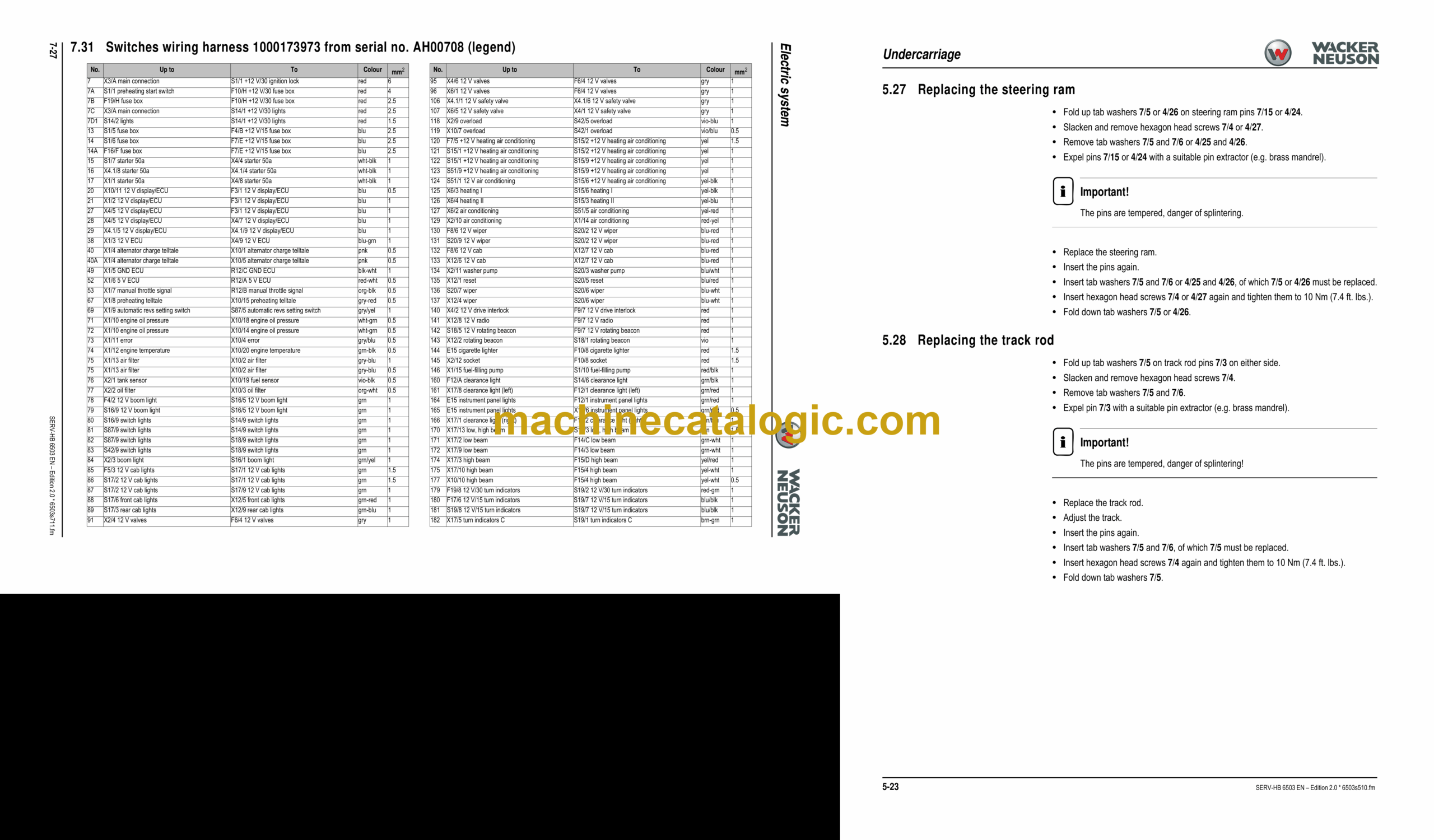
Switches wiring harness 1000173973 from serial no. AH00708 (legend) …………. 7-27
Switches wiring harness 1000173973 from serial no. AH00708 ………………………. 7-29
Cab wiring harness up to serial no. AD07227 (legend) ………………………………….. 7-30
Cab wiring harness up to serial no. AD07227 ……………………………………………….. 7-31
Cab wiring harness 1000174373 from serial no. AH00708 (legend) ………………… 7-32
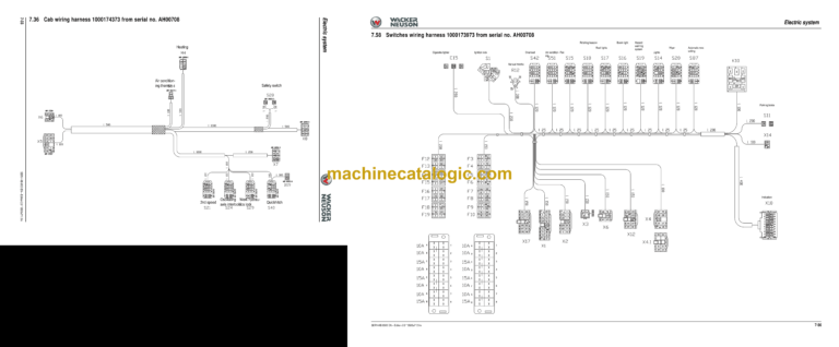
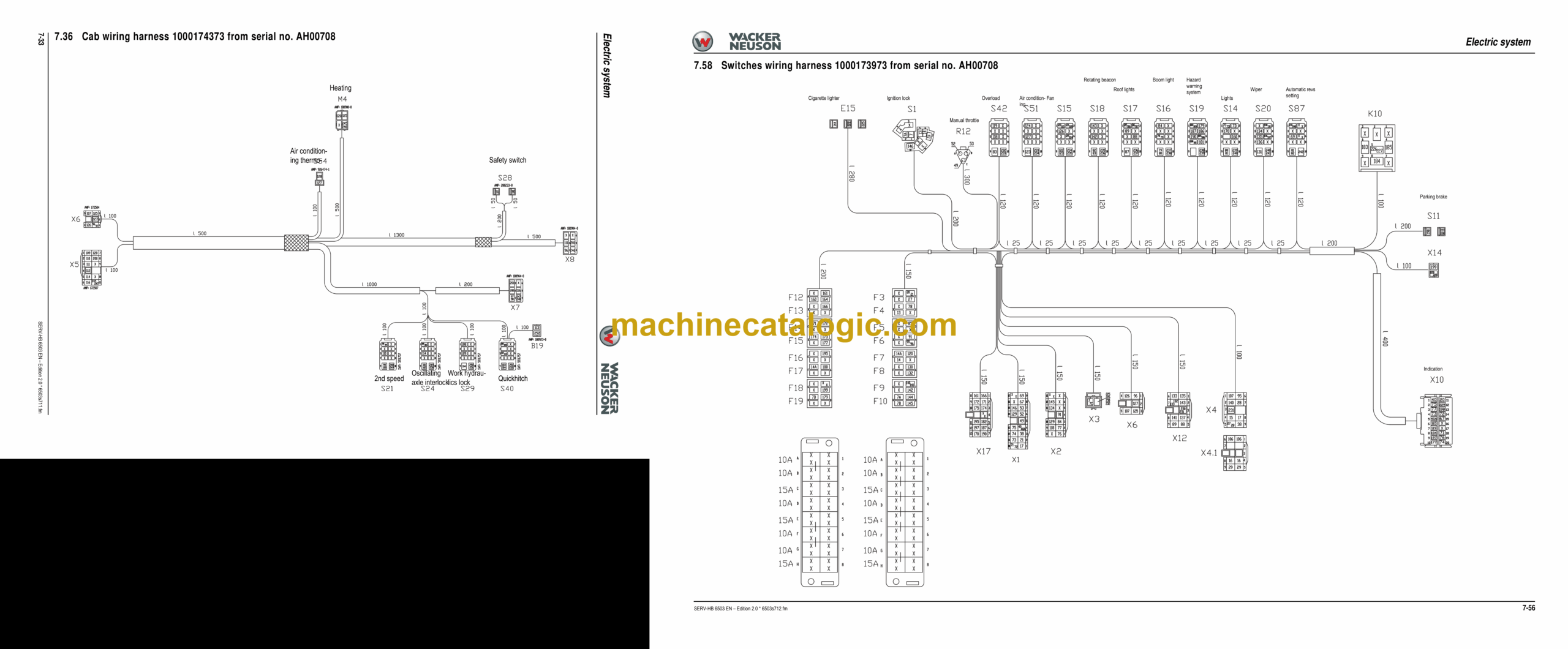
Cab wiring harness 1000174373 from serial no. AH00708 …………………………….. 7-33
Lights wiring harness up to serial no. AD07227 (legend) ……………………………….. 7-34
Lights wiring harness up to serial no. AD07227 …………………………………………….. 7-35
Chassis wiring harness 1000174374 from serial no. AH00708 (legend) …………… 7-36
Chassis wiring harness from serial no. AH00708 (legend) ……………………………… 7-37
Rear lights wiring harness (legend) …………………………………………………………….. 7-38
Rear lights wiring harness ………………………………………………………………………….. 7-39
Wiring diagram up to serial no. AD07227 (legend) ………………………………………… 7-41
Wiring diagram up to serial no. AD07227 …………………………………………………….. 7-42
Wiring diagram from serial no. AH00708 (legend) …………………………………………. 7-43
Wiring diagram 1 from serial no. AH00708 …………………………………………………… 7-44
Wiring diagram 2 from serial no. AH00708 …………………………………………………… 7-45
Wiring diagram 3 from serial no. AH00708 …………………………………………………… 7-46
Wiring diagram for machines with road travel certification A3 (legend) …………….. 7-47
Wiring diagram for machines with road travel certification A3 …………………………. 7-48
Engine wiring harness up to serial no. AD07227 (legend) ………………………………. 7-49
Engine wiring harness up to serial no. AD07227 …………………………………………… 7-50
Engine wiring harness from serial no. AH00708 (legend) ……………………………….. 7-51
Engine wiring harness 1000173970 from serial no. AH00708 …………………………. 7-52
Switches wiring harness up to serial no. AD07227 (legend) ……………………………. 7-53
Switches wiring harness up to serial no. AD07227 ………………………………………… 7-54
Switches wiring harness 1000173973 from serial no. AH00708 (legend) …………. 7-55
Switches wiring harness 1000173973 from serial no. AH00708 ………………………. 7-56
Cab wiring harness up to serial no. AD07227 (legend) ………………………………….. 7-57
Cab wiring harness up to serial no. AD07227 ……………………………………………….. 7-58
Cab wiring harness 1000174373 from serial no. AH00708 (legend) ………………… 7-59
Cab wiring harness 1000174373 from serial no. AH00708 …………………………….. 7-60
Lights wiring harness up to serial no. AD07227 (legend) ……………………………….. 7-61
Lights wiring harness up to serial no. AD07227 …………………………………………….. 7-62
Chassis wiring harness 1000174374 from serial no. AH00708 (legend) …………… 7-63
Chassis wiring harness from serial no. AH00708 (legend) ……………………………… 7-64
Rear lights wiring harness A3 …………………………………………………………………….. 7-65
Options
Air conditioning ………………………………………………………………………………………….. 8-1
Specific safety instructions …………………………………………………………………….. 8-1
SERV-HB 6503 EN – Edition 2.0 * 6503s11IVZ.fm I-9
table of contents
Specifications ………………………………………………………………………………………. 8-1
Installation: overview …………………………………………………………………………….. 8-2
Components ………………………………………………………………………………………… 8-3
Filling up the air conditioning system ……………………………………………………….. 8-5
Maintenance ………………………………………………………………………………………… 8-6
Troubleshooting ……………………………………………………………………………………. 8-7
Air-suspension seat ……………………………………………………………………………………. 8-9
Connections …………………………………………………………………………………………. 8-9
Long stick ………………………………………………………………………………………………….. 8-9
Specifications ………………………………………………………………………………………. 8-9
Control circuit (pipework) connections for grab ………………………………………………. 8-9
3rd control circuit connections ……………………………………………………………………. 8-10
Auxiliary hydraulics connections …………………………………………………………………. 8-10
Quickhitch couplings ……………………………………………………………………………. 8-11
Attachments ……………………………………………………………………………………….. 8-11
Fuel-filling pump ………………………………………………………………………………………. 8-12
Connections up to serial no. AD07227 …………………………………………………… 8-13
Central lubrication system …………………………………………………………………………. 8-14
Position ……………………………………………………………………………………………… 8-14
Ports …………………………………………………………………………………………………. 8-14
Function …………………………………………………………………………………………….. 8-15
Adjusting breaks and lubrication times …………………………………………………… 8-16
Repair in case of clogging ……………………………………………………………………. 8-16
Service valve …………………………………………………………………………………………… 8-18
Function …………………………………………………………………………………………….. 8-18
Safe load indicator D (safety valve for boom) ……………………………………………….. 8-19
Position ……………………………………………………………………………………………… 8-19
Setting the pressure switch ………………………………………………………………….. 8-19
Function …………………………………………………………………………………………….. 8-20
Diagram …………………………………………………………………………………………….. 8-20
Safe load indicator F (safety valves for boom and stick) ………………………………… 8-21
Position ……………………………………………………………………………………………… 8-21
Setting the pressure switch ………………………………………………………………….. 8-21
Function …………………………………………………………………………………………….. 8-22
Diagram …………………………………………………………………………………………….. 8-22
3rd control circuit ……………………………………………………………………………………… 8-24
Function …………………………………………………………………………………………….. 8-24
Diagram …………………………………………………………………………………………….. 8-24
Triple articulation boom …………………………………………………………………………….. 8-25
Function …………………………………………………………………………………………….. 8-25
Diagram …………………………………………………………………………………………….. 8-25
Proportional controls for auxiliary hydraulics ………………………………………………… 8-26
Function …………………………………………………………………………………………….. 8-26
Diagram …………………………………………………………………………………………….. 8-26
Auxiliary hydraulics shock cartridge …………………………………………………………….. 8-27
3rd control circuit shock cartridge ……………………………………………………………….. 8-28
Drive interlock (antitheft protection) …………………………………………………………….. 8-29
Position ……………………………………………………………………………………………… 8-29
Disabling the drive interlock ………………………………………………………………….. 8-29
Enabling the drive interlock ………………………………………………………………….. 8-29
Programming ……………………………………………………………………………………… 8-29
Quickhitch ……………………………………………………………………………………………….. 8-31
Proportional controls …………………………………………………………………………………. 8-32
Function …………………………………………………………………………………………….. 8-32
Ports …………………………………………………………………………………………………. 8-32
Overview ……………………………………………………………………………………………. 8-33
Wiring harness ……………………………………………………………………………………. 8-34
Control unit ………………………………………………………………………………………… 8-34
Control valve plug assignment ………………………………………………………………. 8-35
Safety features ……………………………………………………………………………………. 8-36
Measures to be taken in case of malfunctions …………………………………………. 8-36
Diagnosis display ………………………………………………………………………………… 8-36


