Format: PDF (Printable Document)
File Language: English
File Pages: 270
File Size: 18.51 MB (Speed Download Link)
Brand: Wacker Neuson
Model: EZ53 Tracked Excavator
Type of Document: Service Manual
$ 45
Service manual
1 Operation
1.1 Information on this service manual
1.2 Identification of warnings and dangers
1.3 Designated use and exemption from liability
1.4 Labels
1.5 Machine overview
1.6 Engine compartment (overview)
1.7 Chassis overview
1.8 Raising the cabin
1.9 Towing the machine
1.10 Fire extinguisher
2 Technical data
2.1 Chassis
2.2 Engine
2.3 Hydraulic system
2.4 Travel gear and swivel unit
2.5 Maximum speed
2.6 Traveling drive
2.7 Tracks
2.8 Stabilizer blade
2.9 Electrical system
2.10 Noise levels
2.11 Vibration
2.12 Coolant compound table
2.13 Weight indications
2.14 Hose identification code
2.15 Tightening torques
2.16 Model EZ53 dimensions
2.17 Model EZ53 dimensions VDS
2.18 Lift capacity tables
2.19 Kinematics
2.20 Measuring live ring tolerance
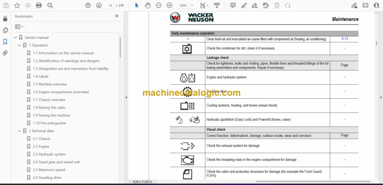
3 Maintenance
3.1 Fluids and lubricants
3.2 Maintenance overview
3.3 Introduction
3.4 Safety-relevant parts
3.5 Fuel system
3.6 Engine lubrication system
3.7 Cooling system
3.8 Air filter
3.9 Washer system
3.10 V-belt
3.11 Air conditioning
3.12 Replace the crankcase breather filter
3.13 Replace the fuel-burner glow plug
3.14 Pressure check
3.15 Test report
3.16 Hydraulic system
3.17 Traveling drive
3.18 Tracks
3.19 Overview of lubrication points
3.20 Electrical system
3.21 Battery
3.22 Cabin
3.23 General maintenance
4 Engine
4.1 Perkins 404F-22T Tier IV/404D-22T Tier III
5 Hydraulic system
5.1 Hydraulic pump PVD-3B-56BCP-21G5-5688A
5.2 Main valve block
5.3 Drive counterbalancing system
5.4 Regeneration – stick section
5.5 Bucket pre-tension
5.6 Flow rate adjustment of auxiliary hydraulics
5.7 Pilot valves
5.8 Valves
5.9 Traveling drive
5.10 Swivel unit
5.11 Swivel joint
5.12 Breather filter
5.13 Malfunctions of the hydraulic system
6 Electrical system
6.1 Ohmic law (current, voltage, resistance); Power
6.2 Measuring equipment, measuring methods
6.3 Cable color coding
6.4 Relays
6.5 Electric units
6.6 Alternator
6.7 Starter
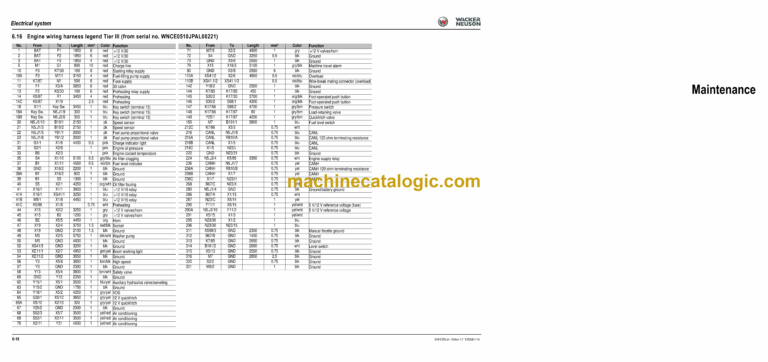
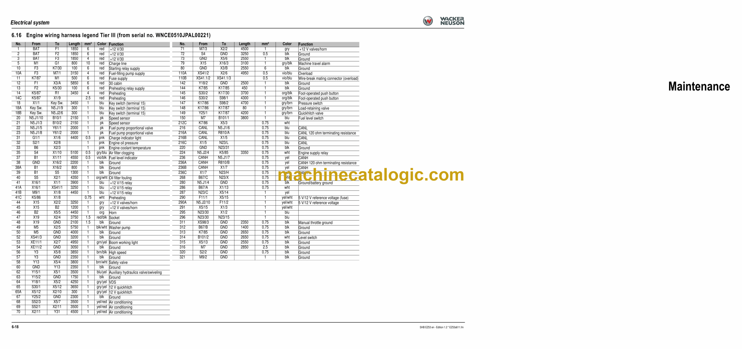
Wiring harnesses
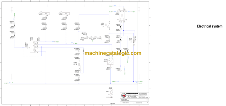
Diagrams
8 Options
8.1 Air conditioning
8.2 Air-suspension seat
8.3 Counterweight
8.4 Long stick
8.5 Control circuit (pipework) connections for grab
8.6 3rd control circuit connections
8.7 Connections for auxiliary hydraulics
8.8 Vantage fuel-filling pump
8.9 Service valve
8.10 Safe load indicator Basic
8.11 Safe load indicator “Advanced”
8.12 Safe load indicator pressure switch
8.13 3rd control circuit
8.14 Electric auxiliary hydraulics
8.15 Auxiliary hydraulics shock cartridge
8.16 3rd control circuit shock cartridge
8.17 Immobilizer
8.18 Proportional controls
8.19 Telematic
Elektroschaltplan_1000353752 EZ53_T3_01.pdf
Stromlaufplan
0 | EZ53 Tier3
1 | EZ53 Tier3
2 | EZ53 Tier3
3 | EZ53 Tier3
5 | EZ53 Tier3
6 | EZ53 Tier3
7 | EZ53 Tier3
8 | EZ53 Tier3
9 | EZ53 Tier3
10 | EZ53 Tier3
11 | EZ53 Tier3
12 | EZ53 Tier3
13 | EZ53 Tier3
Elektroschaltplan_1000345249 EZ53_T4_03.pdf
Stromlaufplan
0 | EZ53 TierIV
1 | EZ53 TierIV
2 | EZ53 TierIV
3 | EZ53 TierIV
4 | EZ53 TierIV
5 | EZ53 TierIV
6 | EZ53 TierIV
7 | EZ53 TierIV
8 | EZ53 TierIV
9 | EZ53 TierIV
10 | EZ53 TierIV
11 | EZ53 TierIV
12 | EZ53 TierIV
13 | EZ53 TierIV
