Format: PDF (Printable Document)
File Language: English
File Pages: 916
File Size: 16.46 MB (Speed Download Link)
Brand: Wacker Neuson
Model: 8075, 8075L, 8085, 8085L, 8095, 8095L Wheel Loader
Type of Document: System Handbook
$ 45
System Handbook
Table of contents
2 Engine
2.1 Technical data, overview of components
2.2 Overview of Deutz TCD 2.9 diesel motor
2.3 Deutz TCD 2.9 lubricant oil system
2.4 Deutz TCD 2.9 fuel system
2.5 Deutz TCD 2.9 cooling system
2.6 Deutz TCD 2.9 exhaust system
2.7 Electrical components TCD 2.9
2.8 Overview of Yanmar 4TNV88 diesel motor
2.9 Yanmar 4TNV88 lubricant oil system
2.10 Yanmar 4TNV88 fuel system
2.11 Yanmar 4TNV88 cooling system
2.12 Starting the diesel engine
2.13 Diesel engine monitoring
3 Cooling
3.1 Cooling test report
4 Power train
4.1 Drive control, variable displacement motor
4.2 Functional description – variable displacement motor drive VIII
4.3 Description: Controls for variable displacement motor
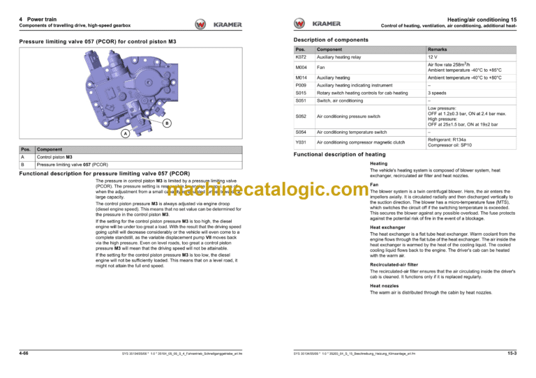
4.4 Components of travelling drive, variable displacement motor
4.5 Checking and making adjustments
4.6 Test report type 351-04 (20 km/h)
4.7 Test report type 351-05 (20 km/h)
4.8 Test report type 351-06 (20 km/h)
4.9 Checking and adjustment instructions / 20 km/h
4.10 Control of travelling drive, high-speed gearbox
4.11 Functional description of travelling drive, variable displacement motor
4.12 Description: Controls for high-speed gearbox
4.13 Components of travelling drive, high-speed gearbox
4.14 Monitoring and adjusting the high-speed gearbox
4.15 Test and adjustment instructions for 30 and 40 km/h version
6 Brakes
6.1 Vehicle brake control
6.2 Control of hydraulic trailer brake
6.3 Test report for brake system
7 Steering
7.1 Steering system control (20 km/h)
7.2 Steering system control (40 km/h)
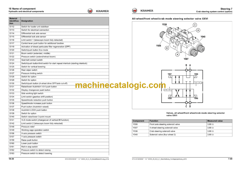
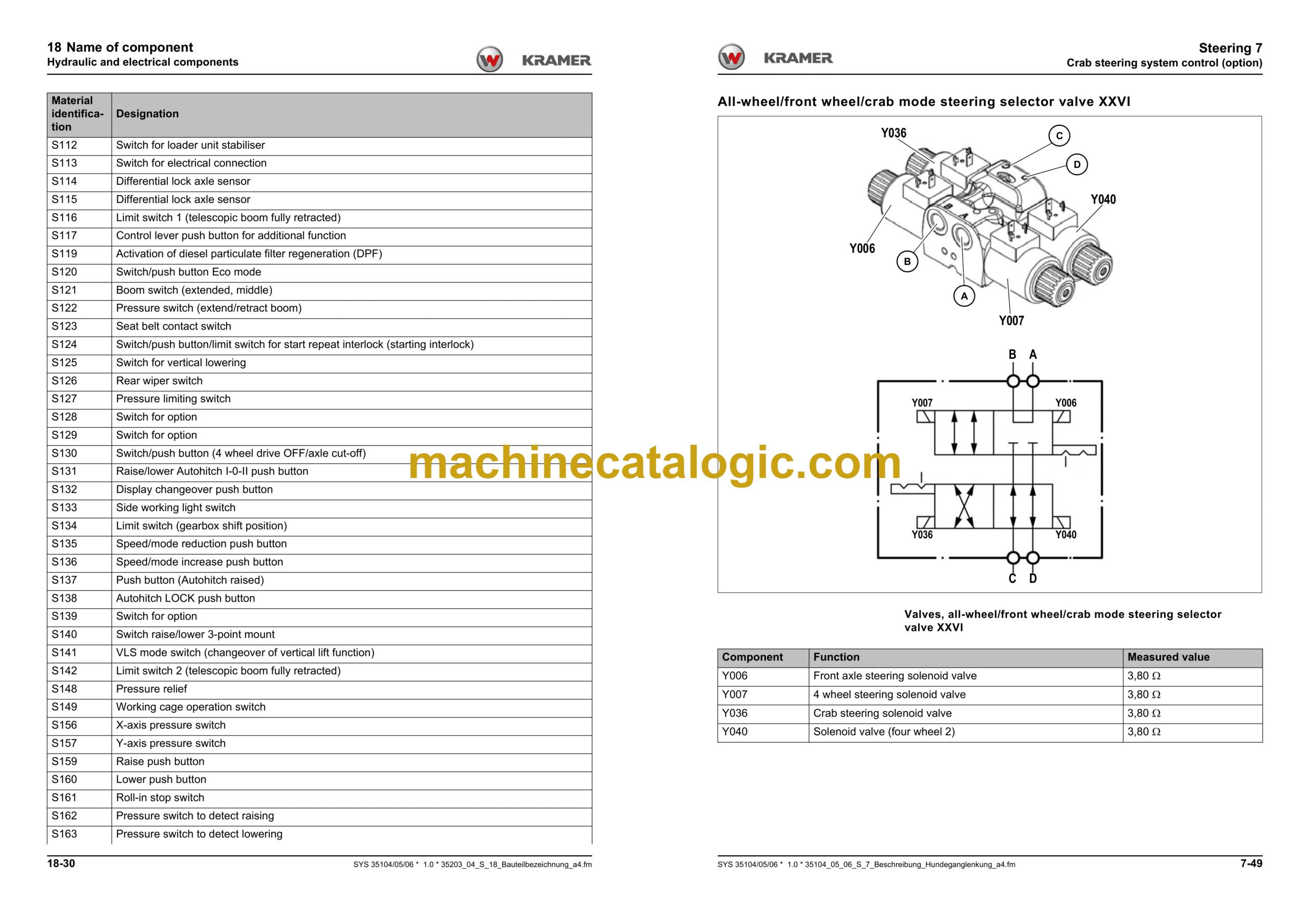
7.3 Crab steering system control (option)
7.4 Test report: steering
8 Hydraulics
8.1 Lifting cylinder control
8.2 Control for lifting cylinder with hose burst valve (option)
8.3 Control for lifting cylinder with load stabiliser (option)
8.4 Lifting cylinder with load stabiliser and hose burst valve (option)
8.5 Tilt ram control
8.6 Control for tilt ram lock
8.7 3rd control circuit (control)
8.8 Auxiliary control circuit 115 + 40 litres rear with tipping trailer
8.9 Throttle valve control
8.10 Checking and making adjustments
8.11 Work hydraulics test report
8.12 Checking and adjustment instructions for working hydraulics
8.13 Hydraulic circuit diagram for control unit
8.14 Hydraulic circuit diagram for travelling drive 20 km/h
8.15 Hydraulic circuit diagram for travelling drive 40 km/h
8.16 Hydraulic circuit diagram for brake
8.17 Hydraulic circuit diagram for steering
8.18 Hydraulic circuit diagram for working hydraulics
9 Electrical system
9.1 CAN signals
9.2 Inputs/outputs for traction electronics N001
9.3 Inputs/outputs MVCU N004
9.4 Inputs/outputs for diesel engine electronics N005
9.5 Inputs for indicating instrument P014
9.6 Inputs/outputs for steering electronics D001
9.7 Fuses, relays, colour coding, circuits
9.8 Indicators (electrical diagram)
9.9 Working lights (electrical diagram)
9.10 Lights (electrical diagram)
9.11 Brakes (electrical diagram)
9.12 CAN, diagnostics and supply (electrical diagram)
9.13 Deutz diesel engine (electrical diagram)
9.14 Differential lock (electrical diagram)
9.15 Throttle (electrical diagram)
9.16 Pressure relief (electrical diagram)
9.17 Drive (electrical diagram)
9.18 Driver’s seat (electrical diagram)
9.19 Front socket (electrical diagram)
9.20 Manual throttle (electrical diagram)
9.21 Heating/air conditioning (electrical diagram)
9.22 Hydraulic trailer brake (electrical diagram)
9.23 Tilt cylinder lock/load stabiliser (electrical diagram)
9.24 Deutz fuel preheater (electrical diagram)
9.25 Cooling/reversing (electrical diagram)
9.26 Steering system (electrical diagram)
9.27 Multimedia (electrical diagram)
9.28 Reversing warning system (electrical diagram)
9.29 Rotating beacon (electrical diagram)
9.30 Bucket repositioning (electrical diagram)
9.31 Window heating (electrical diagram)
9.32 Float position (electrical diagram)
9.33 Searchlight (electrical diagram)
9.34 Telematics (electrical diagram)
9.35 Monitoring elements (electrical diagram)
9.36 Washer system (electrical diagram)
9.37 12 V power outlet (electrical diagram)
9.38 Auxiliary circuits (electrical diagram)
15 Heating/air conditioning
15.1 Control of heating, ventilation, air conditioning, additional heating
18 Name of component
18.1 Hydraulic and electrical components
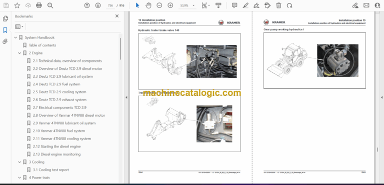
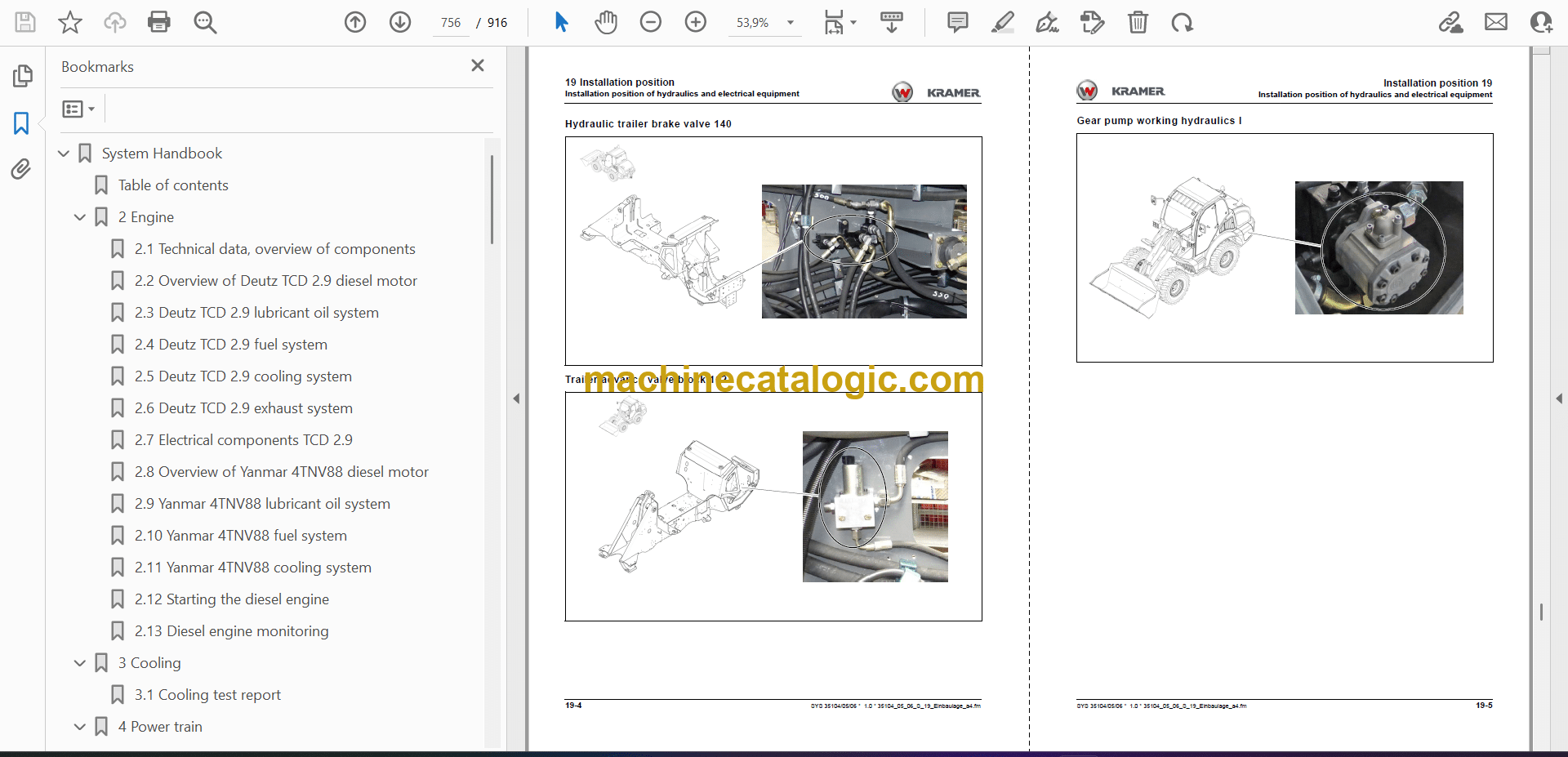
19 Installation position
19.1 Installation position of hydraulics and electrical equipment
20 Switch
20.1 Switch assignment, installation point
22 Error code
22.1 Error codes for drive electronics N001
22.2 Error codes for MVCU N004
22.3 Error code for diesel engine electronics N005
