Format: PDF (Printable Document)
File Language: English
File Pages: 216
File Size: 15.09 MB (Speed Download Link)
Brand: Wacker Neuson
Model: 38Z3 Tracked Excavator
Type of Document: Service Manual
$ 45
1 Operation
1.1 Notices on this service manual
1.2 Identification of warnings and dangers
1.3 Designated use and exemption from liability
1.4 Type labels and component numbers
1.5 Machine overview
1.6 Cab overview
1.7 Cab (legend)
1.8 Instrument panel overview (up to serial no. AE02803)
1.9 Instrument panel legend
1.10 Instrument panel overview (from serial no. AG00573)
1.11 Instrument panel legend
1.12 Engine compartment overview (Tier 2 up to AE02803)
1.13 Engine compartment overview (Tier 3A from AG00573)
1.14 Chassis overview
1.15 Raising/lowering the cab
2 Specifications
2.1 Chassis
2.2 Engine
2.3 Hydraulic system
2.4 Travel gear and swivel unit
2.5 Stabilizer blade
2.6 Electrical system
2.7 Noise levels
2.8 Vibration
2.9 Coolant compound table
2.10 Model-specific tightening torques
2.11 General tightening torques
2.12 Dimensions model 38Z3
2.13 Lift capacity table 38Z3
2.14 Kinematics
2.15 Attachments
3 Maintenance
3.1 Fluids and lubricants
3.2 Maintenance label
3.3 Maintenance plan (overview)
3.4 Introduction
3.5 Fuel system
3.6 Engine lubrication system
3.7 Cooling system
3.8 Air filter
3.9 V-belt
3.10 Pressure check
3.11 Test report
3.12 Hydraulic system
3.13 Travelling drive
3.14 Tracks
3.15 Lubrication work
3.16 Electrical system
3.17 Cab
3.18 General maintenance work
4 Engine
4.1 Engine 3TNV88-PNS (up to serial no. AE02803)
4.2 Fuel system
4.3 Checking and adjusting valve clearance
4.4 Tightening order for cylinder head bolts
4.5 Checking the injection nozzles
4.6 Checking the nozzle jet
4.7 Injection time
4.8 Adjusting engine speed
4.9 Compression
4.10 Checking the coolant thermostat
4.11 Checking the thermal switch
4.12 Oil pressure switch
4.13 Checking the coolant circuit
4.14 Engine 3TNV88-BPNS (from serial no. AG00573)
4.15 Fuel system
4.16 Removing the valve cover
4.17 Checking and adjusting valve clearance
4.18 Tightening order for cylinder head bolts
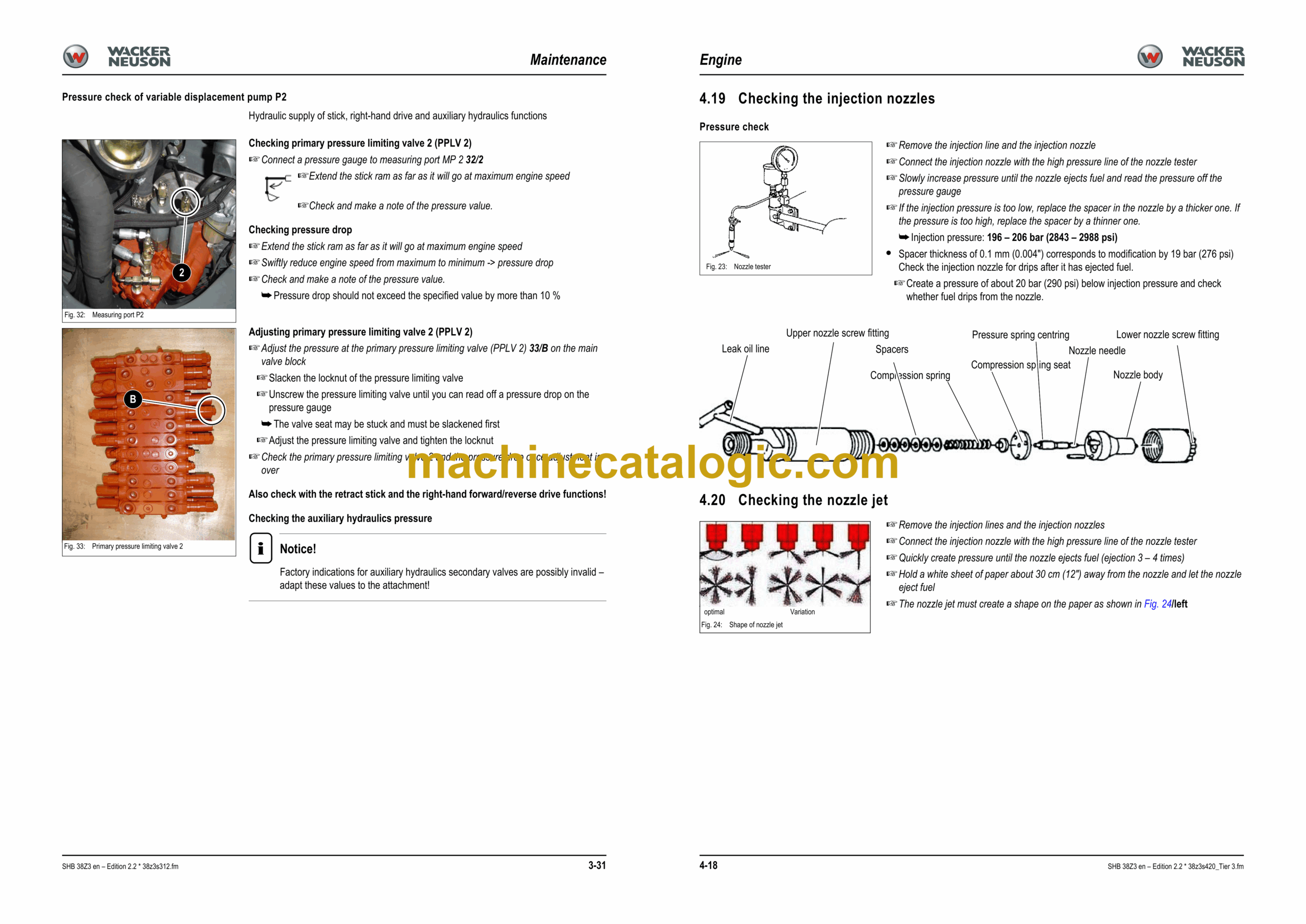
4.19 Checking the injection nozzles
4.20 Checking the nozzle jet
4.21 Injection time
4.22 Adjusting engine speed
4.23 Compression
4.24 Checking the coolant thermostat
4.25 Checking the thermal switch
4.26 Oil pressure switch
4.27 Checking the coolant circuit
4.28 Engine trouble
5 Hydraulic system
5.1 Hydraulic pump PVD-1B-32BP-11G5-4904A
5.2 Main valve block
5.3 Drive counterbalancing system
5.4 Regeneration – stick section
5.5 Bucket pre-tension
5.6 Flow rate adjustment of auxiliary hydraulics
5.7 Pilot valves
5.8 Valves
5.9 Travelling drive up to no. AE00854
5.10 Travelling drive starting no. AE00855
5.11 Swivel unit
5.12 Swivel joint
5.13 Breather filter
5.14 Troubleshooting in the hydraulic system
5.15 Hydraulics diagram A4
5.16 Hydraulics diagram (legend)
5.17 Hydraulics diagram 38Z3 A3
5.18 Options diagram 1
5.19 Options diagram 2
5.20 Main valve block diagram 38Z3 A3
6 Electrical system
6.1 Ohm’s Law (current, voltage, resistance); power
6.2 Measuring equipment, measuring methods
6.3 Cable colour coding
6.4 Relays
6.5 Electric units
6.6 Fuse box in instrument panel
6.7 Main fuse box with relays
6.8 Relays
6.9 Socket
6.10 Joystick tip switches
6.11 Instrument panel overview
6.12 Switches overview (up to serial no. AE02803)
6.13 Switch overview (from serial no. AG00573)
6.14 Alternator
6.15 Starter
6.16 Wiring diagram (legend)
6.17 Wiring diagram
6.18 Engine wiring harness legend (up to serial no. AG03204)
6.19 Engine wiring harness (up to serial no. AG03204)
6.20 Engine wiring harness legend (from serial no. AG03205)
6.21 Engine wiring harness (from serial no. AG03205)
6.22 Cab wiring harness legend
6.23 Cab wiring harness
6.24 Roof wiring harness
6.25 Engine speed control wiring harness (option)
7 Options
7.1 Air conditioning
7.2 Counterweight
7.3 Long stick
7.4 Control circuit (pipework) connections for grab
7.5 3rd control circuit connections
7.6 Auxiliary hydraulics connections
7.7 Safe load indicator DE (safety valve for boom)
7.8 Safe load indicator FR (safety valves for boom and stick)
7.9 3rd control circuit
7.10 Drive interlock (antitheft protection)
7.11 Proportional controls
7.12 Fuel-filling pump
7.13 Service valve
7.14 Automatic engine speed setting (Tier 3A from AG00573


