Format: PDF (Printable Document)
File Language: English
File Pages: 246
File Size: 13.75 MB (Speed Download Link)
Brand: Wacker Neuson
Model: RD27 Roller
Type of Document: Service Manual
$ 45
1. Safety Information
1.1 Operating Safety
1.2 Operator Safety while using Internal Combustion Engines
1.3 Service Safety
1.4 Label Locations
1.5 Warning & Informational Labels
2. Technical Data
2.1 Engine
2.2 Roller
2.3 Lubrication
2.4 Sound Measurements
2.5 Measurements of Operator Exposure to Vibration
2.6 Dimensions
3. Maintenance
3.1 Maintenance Schedule
3.2 Recommended Products and Amounts
3.3 Oil/Temperature Table
3.4 Battery
3.5 Inspecting the ROPS
3.6 Lifting the Machine
3.7 Tying Down the Machine
3.8 Engine Oil
3.9 Testing Backup Alarm
3.10 Engine Air Filter
3.11 Fuel System Water Separator
3.12 Hydraulic Oil
3.13 Engine Cooling System
3.14 Cleaning Radiator Core
3.15 Sprinkler Efficiency
3.16 Inspecting and Adjusting Belts
3.17 Fuses
3.18 Shockmounts
3.19 Scraper Wear
3.20 Lubricating Articulated Steering Joint
3.21 Lubricating Steering Cylinder
3.22 Lubricating Throttle Control
3.23 General Cleaning
3.24 Cleaning the Fuel Tank
3.25 Towing
3.26 Manually Releasing Parking Brakes
3.27 Exhaust System and Engine Air Intake System
3.28 Storage
3.29 Electrical Schematics
3.30 Hydraulic Schematic
4. Engine Starting Troubleshooting
4.1 Starting System Component Locations
4.2 Troubleshooting Flowcharts
4.3 Engine Does Not Crank
4.4 Checking Power at Starter Motor Solenoid
4.5 Checking Neutral/Brake Fuse
4.6 Checking Power to/from Starter Relay 1
4.7 Checking Power to/from Starter Relay 2
4.8 Checking Key Switch
4.9 Checking Power to/from Neutral Switch Relay
4.10 Checking Neutral Switch
4.11 Checking Fuses
4.12 Checking 60A Circuit Breaker
4.13 Checking Power to/from Main Power Relay
4.14 Engine Cranks but does not Start
4.15 Checking Fuel Flow
4.16 Checking Power to Fuel Shutoff Solenoid
4.17 Checking Power to/from Glow Plug Relay
4.18 Checking Glow Plugs
5. Drive System Electricals
5.1 Drive System Electrical Overview
5.2 Drive System Component Locations
5.3 Troubleshooting Flowcharts
5.4 Machine does not Drive (Propel) Troubleshooting
5.5 Checking Neutral/Brake Solenoid
5.6 Checking Seat Switch Solenoid
5.7 Checking Power to Brake Switch
5.8 Checking Power to/from Brake 1 Relay
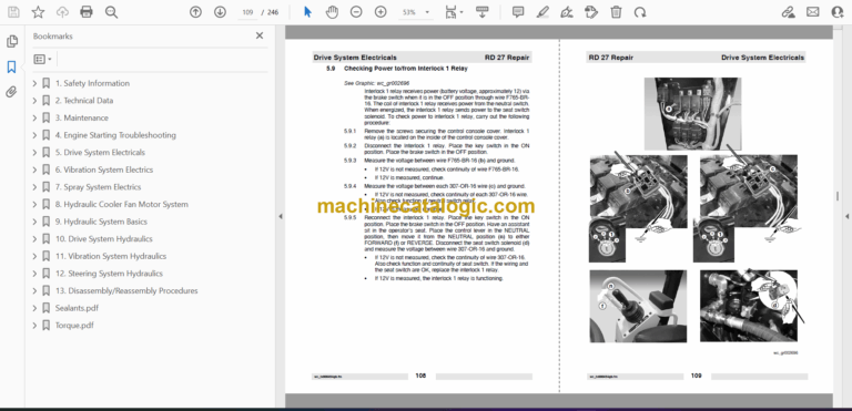
5.9 Checking Power to/from Interlock 1 Relay
5.10 Checking Function of Seat Switch
6. Vibration System Electrics
6.1 Vibration System Electrical Overview
6.2 Vibration System Electrical Component Locations
6.3 Checking the Vibration System Fuse
6.4 Checking Power to the Vibration Solenoids
6.5 Checking Drum Selector Switch
7. Spray System Electrics
7.1 Spray System Electrical Overview
7.2 Spray System Troubleshooting
7.3 Checking the Spray System Fuse
7.4 Checking the Spray System Switch
7.5 Checking Power to/from Spray System Relay
7.6 Checking Power to the Spray System Pump
8. Hydraulic Cooler Fan Motor System
8.1 Checking Fan Motor Operation
9. Hydraulic System Basics
9.1 Hydraulic System Precautions
9.2 Hydraulic System Service Basics
9.3 Relieving Pressure in Hydraulic Tank
9.4 Component Locations
9.5 Analyzing Hydraulic Oil Contamination
10. Drive System Hydraulics
10.1 Drive System Hydraulic Overview
10.2 Drive System Hydraulic Diagram
10.3 Troubleshooting Drive System
10.4 Checking/Adjusting Charge Pressure
10.5 Checking Main Relief Valve
10.6 Checking and Adjusting Drive Pump Neutral Setting
10.7 Testing the Parking Brake
10.8 Testing Motor Case Drain Flow
11. Vibration System Hydraulics
11.1 Vibration System Overview
11.2 Vibration System Electrical Diagram
11.3 Troubleshooting Vibration System
11.4 Testing Vibration Pump Flow
11.5 Testing and Adjusting Vibration Valve Main Relief
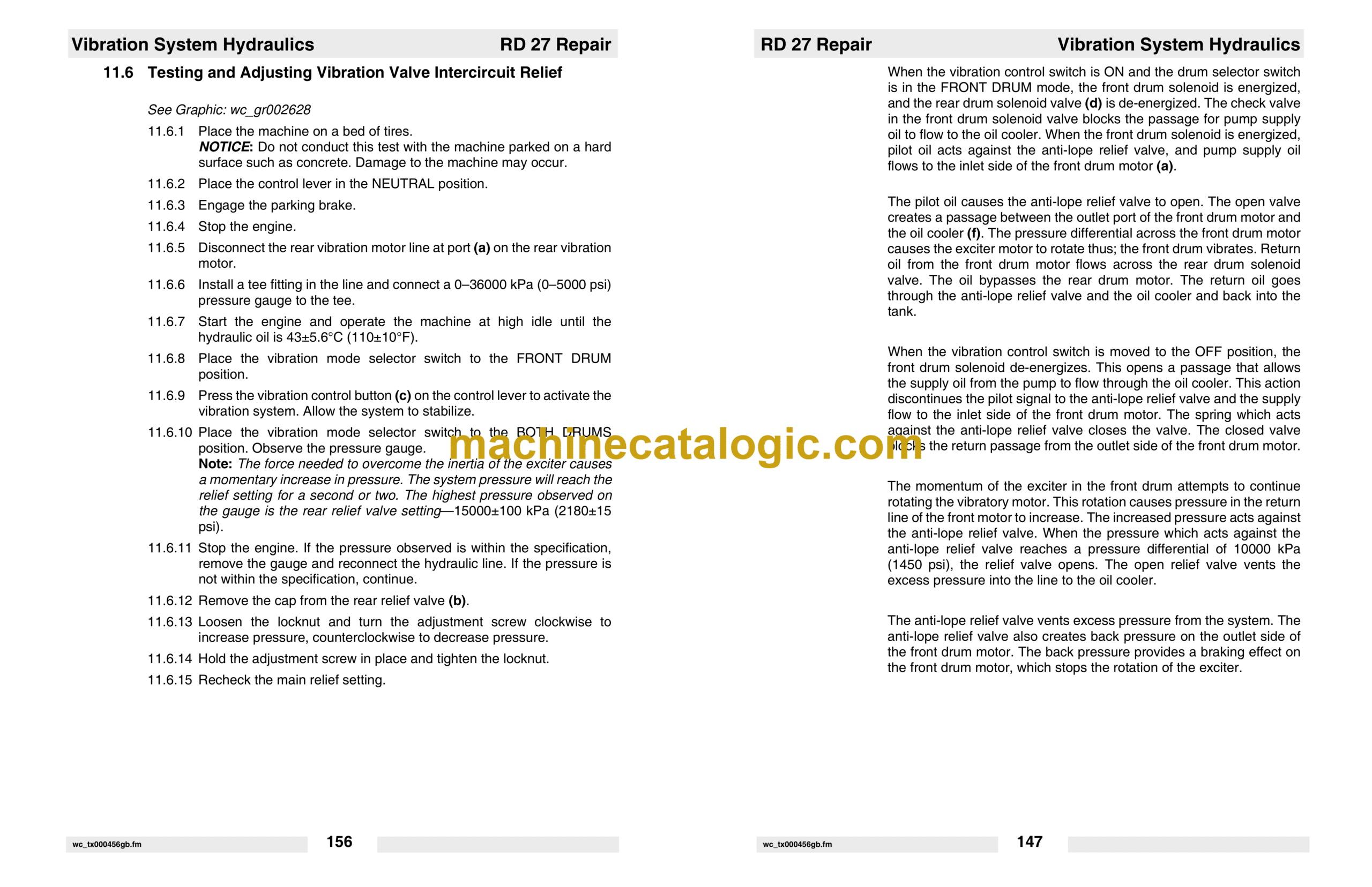
11.6 Testing and Adjusting Vibration Valve Intercircuit Relief
11.7 Testing and Adjusting Vibration Valve Anti-Lope Relief
11.8 Testing Vibration Motor Case Drain Flow
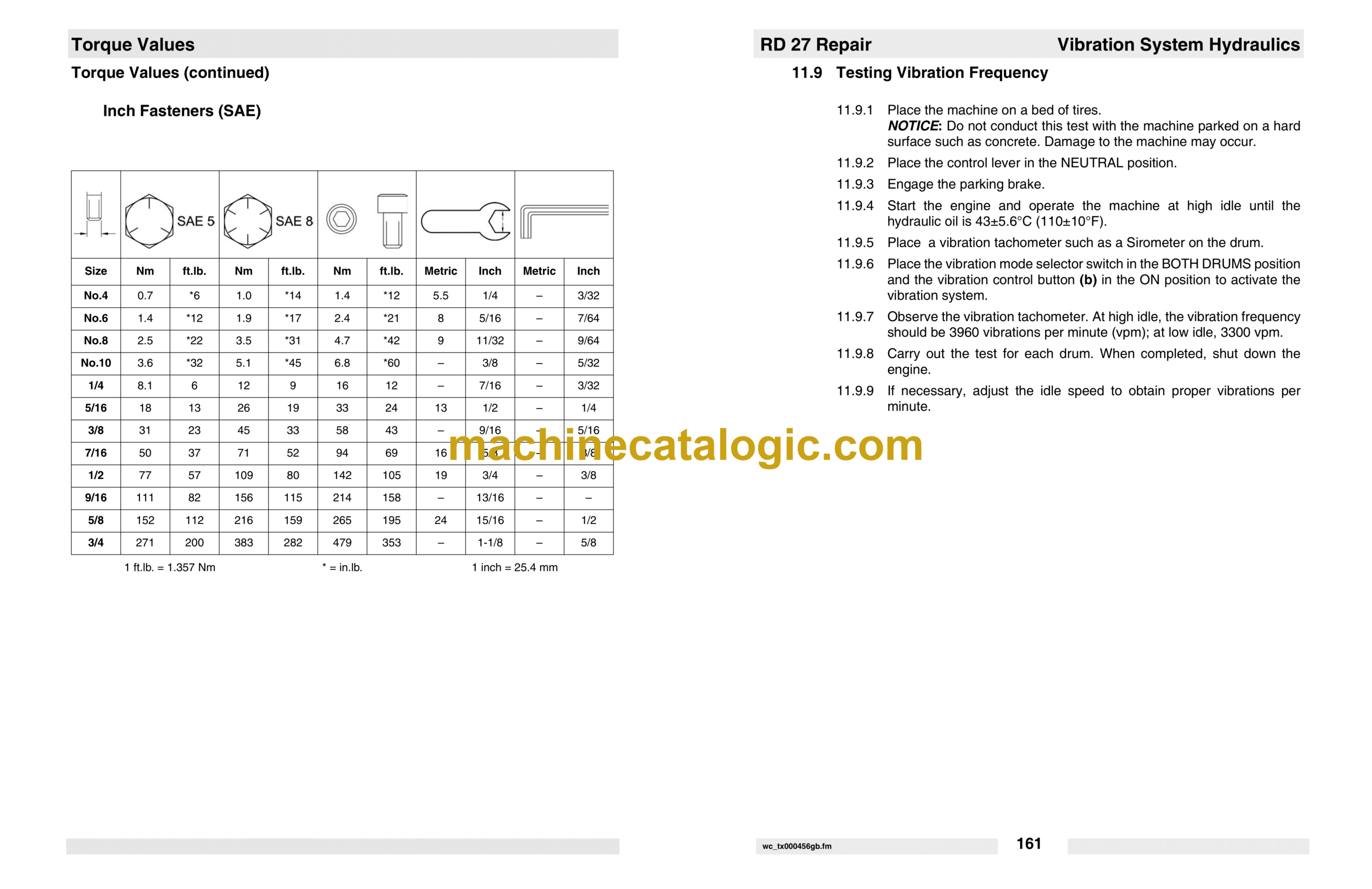
11.9 Testing Vibration Frequency
12. Steering System Hydraulics
12.1 Steering System Overview
12.2 Steering System Hydraulic Diagram
12.3 Steering System Troubleshooting
12.4 Testing Steering Pump Flow
12.5 Testing Steering Unit Relief Valve
12.6 Checking Steering Time
13. Disassembly/Reassembly Procedures
13.1 Tools
13.2 Ordering Parts
13.3 Reference Numbers ( )
13.4 Weight Block
13.5 Removing and Installing Steering Servo Valve
13.6 Removing and Installing Drive Motors
13.7 Removing and Installing Exciter Motor
13.8 Removing Drum
13.9 Disassembling Drum
13.10 Exciter Shaft Bearings
13.11 Drum Shock Mounts
13.12 Reassembling Drum
13.13 Remounting Drum
13.14 Removing and Installing Fuel Tank
13.15 Removing and Installing Radiator
13.16 Removing and Installing Vibration Pump Belts
13.17 Removing and Installing Steering Cylinder
13.18 Removing and Installing Articulated Steering Joint
13.19 Articulated Steering Joint Exploded View
13.20 Articulated Steering Joint Components
13.21 Rebuilding Articulated Steering Joint
13.22 Removing and Installing Spray System Water Pump
13.23 Removing and Installing Water Tank
13.24 Removing and Installing Hydraulic Oil Cooler
13.25 Removing and Installing Drive Pump
13.26 Removing Engine
13.27 Installing the Engine
13.28 Removing and Installing the Hydraulic Oil Tank
13.29 Removing and Installing Vibration Pump
13.30 Removing and Installing Steering Pump
Sealants.pdf
Threadlockers and Sealants
Torque.pdf
Torque Values
Metric Fasteners (DIN)
Inch Fasteners (SAE)


