Format: PDF (Printable Document)
File Language: English
File Pages: 266
File Size: 13.70 MB (Speed Download Link)
Brand: Wacker Neuson
Model: EZ38 Tracked Excavator
Type of Document: Service Manual
$ 45
1 Operation
1.1 Information on this service manual
1.2 Identification of warnings and dangers
1.3 Explanation of symbols and abbreviations
1.4 Warranty and liability
1.5 Labels
1.6 Machine overview
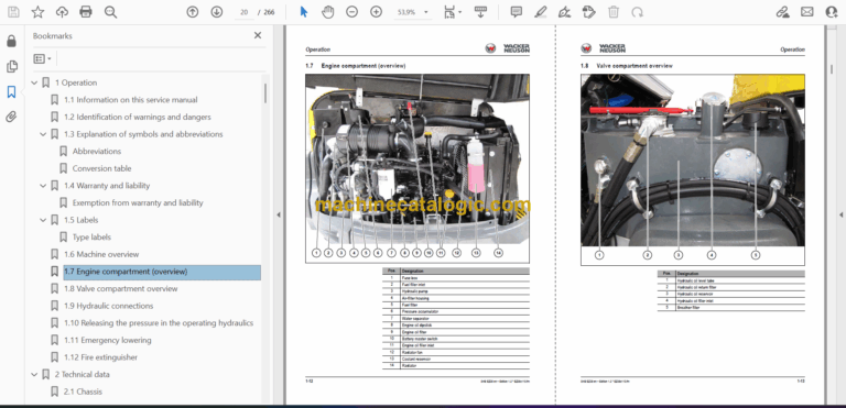
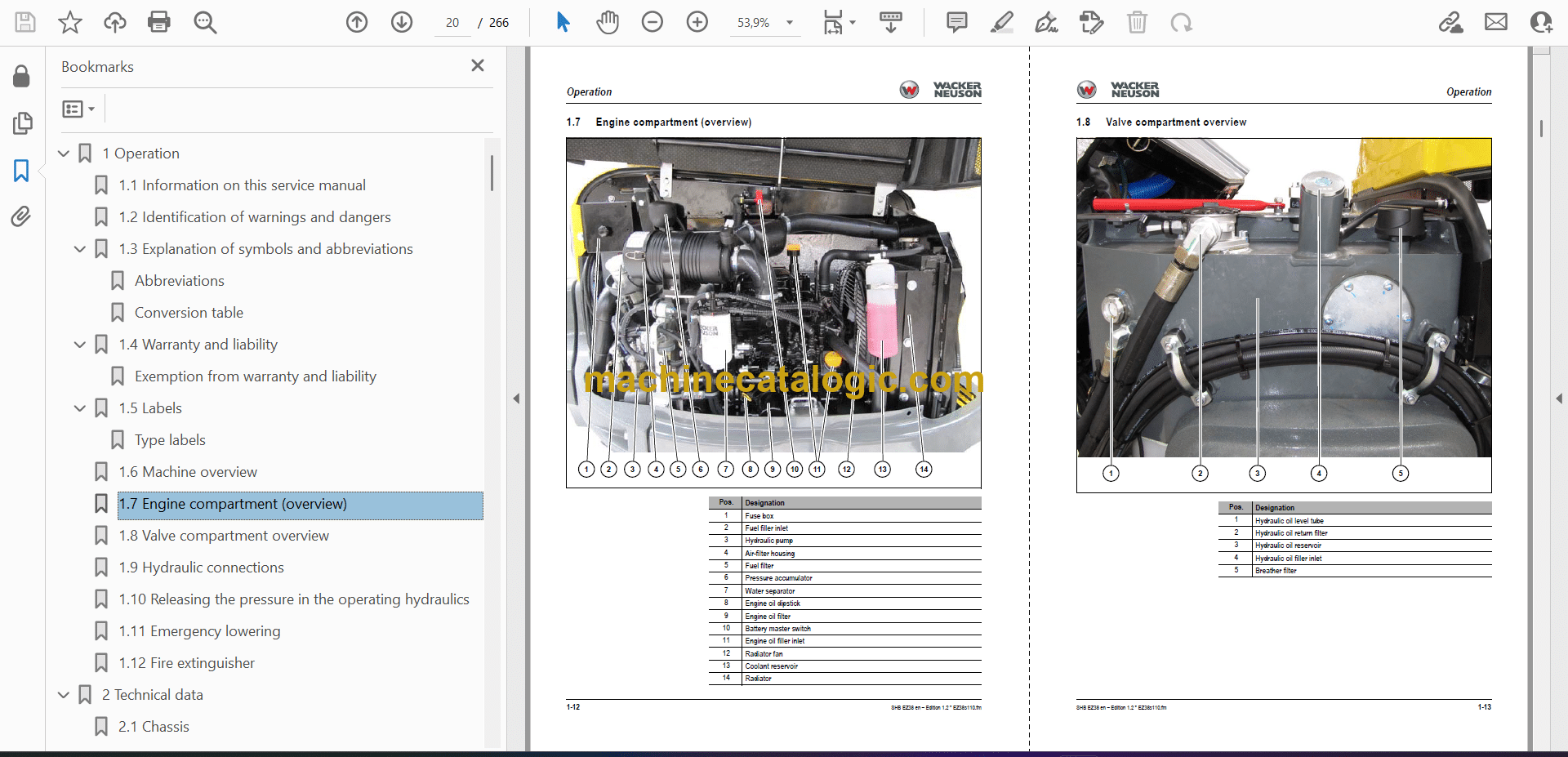
1.7 Engine compartment (overview)
1.8 Valve compartment overview
1.9 Hydraulic connections
1.10 Releasing the pressure in the operating hydraulics
1.11 Emergency lowering
1.12 Fire extinguisher
2 Technical data
2.1 Chassis
2.2 Engine
2.3 Operating hydraulics
2.4 Traveling drive/axles
2.5 Brakes
2.6 Tracks
2.7 Steering system
2.8 Speed
2.9 Vibration
2.10 Coolant
2.11 Electrical system
2.12 Powertilt (option)
2.13 Noise emissions
2.14 Weight
2.15 Excavator forces
2.16 Ground clearance/ground pressure
2.17 Tightening torques
2.18 Payload/stability
2.19 Dimensions
2.20 Kinematics
2.21 Measuring live ring tolerance
3 Maintenance
3.1 Information on maintenance
3.2 Fluids and lubricants
3.3 Maintenance overview
3.4 Lubrication work
3.5 Maintenance plan
3.6 Maintenance accesses
3.7 Fuel system
3.8 Engine lubrication system
3.9 Cooling system
3.10 Air filter
3.11 V-belt
3.12 Heating/ventilation/air conditioning
3.13 Replacing the crankcase breather filter
3.14 Washer system
3.15 Pressure check
3.16 Test report
3.17 Hydraulic system
3.18 Axles/traveling drive
3.19 Tires/tracks
3.20 Maintenance of attachments
3.21 Maintenance of options
3.22 Cleaning and maintenance
3.23 Exhaust gas treatment
3.24 Machine preservation
3.25 Electrical system
4 Engine
4.1 Engine 3TNV88-BPNS
4.2 Fuel system
4.3 Removing the cylinder-head cover
4.4 Checking and adjusting valve clearance
4.5 Tightening order for cylinder head bolts
4.6 Checking the injection nozzles
4.7 Checking the nozzle jet
4.8 Injection time
4.9 Adjusting engine speed
4.10 Compression
4.11 Checking the coolant thermostat
4.12 Checking the thermal switch
4.13 Oil pressure switch
4.14 Checking the coolant circuit
4.15 Engine malfunctions
4.16 Engine 3TNV88F-EPNS (Tier IV)
4.17 Fuel system
4.18 Removing the cylinder-head cover
4.19 Checking and adjusting valve clearance
4.20 Tightening order for cylinder head bolts
4.21 Checking the injection nozzles
4.22 Checking the nozzle jet
4.23 Injection time
4.24 Compression
4.25 Checking the coolant temperature sensor
4.26 Checking the coolant thermostat
4.27 Oil pressure switch
4.28 Checking the coolant circuit
4.29 Engine malfunctions
5 Hydraulic system
5.1 Hydraulic pump PVD-1B-32BP-11G5-4904A / PVD-1B-32BCP-11G5-5596Z
5.2 Main valve block
5.3 Drive counterbalancing system
5.4 Regeneration – stick section
5.5 Bucket pre-tension
5.6 Flow rate adjustment of auxiliary hydraulics
5.7 Pilot valves
5.8 Valves
5.9 Traveling drive
5.10 Swivel unit
5.11 Swivel joint
5.12 Swivel joint VDS (option)
5.13 Breather filter
5.14 Malfunctions in the hydraulic system
6 Electrical system
6.1 Ohm’s Law (current, voltage, resistance); power
6.2 Measuring equipment, measuring methods
6.3 Cable color coding
6.4 Relays
6.5 Socket
6.6 Alternator
6.7 Starter
6.8 Cabin switches wiring harness (legend)
6.9 Cabin switches wiring harness
6.10 Legend: engine/chassis wiring harness (Yanmar 3TNV88-BPNS)
6.11 Engine/chassis wiring harness (Yanmar 3TNV88-BPNS)
6.12 Legend: engine/chassis wiring harness (Yanmar 3TNV88F-EPNS)
6.13 Engine/chassis wiring harness (Yanmar 3TNV88F-EPNS)
6.14 Legend: seat console wiring harness (Yanmar 3TNV88-BPNS)
6.15 Seat console wiring harness (Yanmar 3TNV88-BPNS)
6.16 Legend: seat console wiring harness (Yanmar 3TNV88F-EPNS)
6.17 Seat console wiring harness (Yanmar 3TNV88F-EPNS)
6.18 Cabin wiring harness (legend)
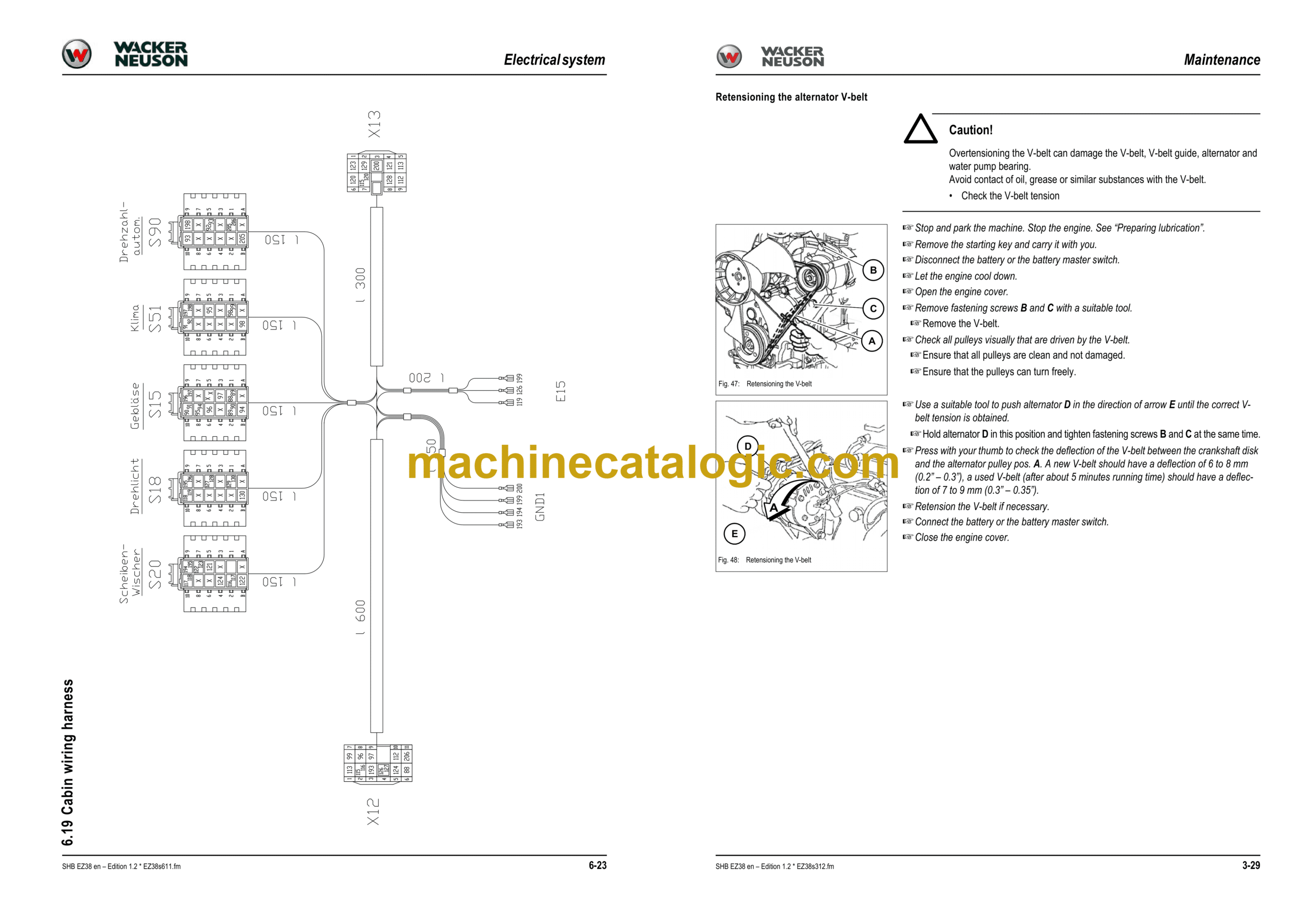
6.19 Cabin wiring harness
6.20 Cabin roof wiring harness
6.21 Canopy lights wiring harness
6.22 Proportional controls wiring harness (option)
6.23 Fuel-filling pump wiring harness (option)
6.24 Immobilizer wiring harness (option)
6.25 Rotating beacon cable
6.26 Boom light cable
6.27 Wiring harness for output regulation (from serial number WNCE0702CPAL00901)
7.28 Hydraulics diagram
7.29 Main valve block
7.30 Electrical diagrams
7.31 Electrical diagram 1
7.32 Electrical diagram 2
7.33 Electrical diagram for output regulation (from serial number WNCE0702CPAL00901)
7.34 Electrical diagram Tier IV ECO
8 Options
8.1 Air conditioning
8.2 Counterweight
8.3 Long stick
8.4 Safe load indicator
8.5 Hydraulic quickhitch valve
8.6 Easy Lock emergency unlocking
8.7 Immobilizer
8.8 Service valve
8.9 Telematic
9 Special tools PA


