Format: PDF (Printable Document)
File Language: English
File Pages: 466
File Size: 69.01 MB (Speed Download Link)
Brand: Case
Model: CX70E, CX75E Mini Excavator
Part No: 92646624
Date: November 2024
Type of Document: Operators Manual
$ 45
1 – INTRODUCTION………………………………………………………………………… 1-1
1.1 – Regarding this manual……………………………………………………………………………. 1-1
1.1.1 – Manual consultation and terminology……………………………………………………………. 1-3
1.2 – Machine identification data………………………………………………………………………. 1-7
1.3 – Manufacturer……………………………………………………………………………………… 1-11
1.3.1 – Contact the after-sales network…………………………………………………………………. 1-11
1.3.2 – Spare Parts…………………………………………………………………………………………… 1-12
1.4 – Information to the owner of the machine………………………………………………….. 1-13
1.5 – Intended use……………………………………………………………………………………… 1-14
1.6 – Prohibited use…………………………………………………………………………………….. 1-15
1.7 – Emissions overview………………………………………………………………………………. 1-17
2 – SAFETY…………………………………………………………………………………….. 2-1
2.1 – Safety symbol……………………………………………………………………………………….2-1
2.2 – General safety……………………………………………………………………………………….2-1
2.2.1 – Consulting the safety signs in the manual………………………………………………………. 2-3
2.3 – Safety signs and operation related labels…………………………………………………….. 2-5
2.4 – Machine driver……………………………………………………………………………………. 2-19
2.4.1 – Personal Protective Equipment (PPE)………………………………………………………….. 2-21
2.5 – Work Area – Hazard Zone – No Entry Zone…………………………………………………. 2-22
2.6 – List of Residual Risks……………………………………………………………………………. 2-24
2.7 – Safety procedures………………………………………………………………………………… 2-33
2.8 – Safety devices…………………………………………………………………………………….. 2-50
2.8.1 – Operator protective structure……………………………………………………………………. 2-50
2.8.1.1 – TOP-GUARD Level II protective grid…………………………………………………………. 2-51
2.8.1.2 – FRONT-GUARD Level II protective grid (optional)………………………………………… 2-51
2.8.2 – Seat belt………………………………………………………………………………………………. 2-52
2.8.3 – Control cut-out lever……………………………………………………………………………….. 2-53
2.8.4 – Location of fire extinguisher……………………………………………………………………… 2-54
3 – TECHNICAL DATA………………………………………………………………………. 3-1
3.1 – General data………………………………………………………………………………………… 3-1
3.2 – Engine………………………………………………………………………………………………… 3-2
3.3 – Hydraulic system…………………………………………………………………………………… 3-3
3.4 – Performances……………………………………………………………………………………….. 3-4
3.5 – Digging arm………………………………………………………………………………………….3-4
3.6 – Counterweight……………………………………………………………………………………… 3-5
3.7 – Dozer blade…………………………………………………………………………………………. 3-6
3.8 – Undercarriage………………………………………………………………………………………. 3-6
3.9 – Fluid capacities……………………………………………………………………………………… 3-7
3.10 – Electrical system…………………………………………………………………………………..3-7
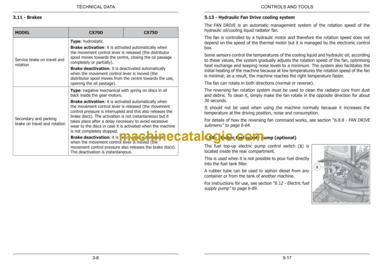
3.11 – Brakes……………………………………………………………………………………………….3-8
3.12 – Nominal lifting capacity…………………………………………………………………………. 3-9
3.13 – Rotary structure………………………………………………………………………………… 3-28
3.14 – Overall dimensions…………………………………………………………………………….. 3-28
4 – TRANSPORTING THE MACHINE…………………………………………………… 4-1
4.1 – Shipping dimensions………………………………………………………………………………. 4-1
4.2 – Loading/unloading operations…………………………………………………………………… 4-1
4.3 – Securing the machine on the means of transport………………………………………….. 4-4
4.4 – Lifting the machine…………………………………………………………………………………4-8
4.4.1 – Lifting procedure……………………………………………………………………………………… 4-9
4.5 – Recovering and towing the machine………………………………………………………… 4-12
5 – CONTROLS AND TOOLS………………………………………………………………. 5-1
5.1 – Description of main controls and levers……………………………………………………….5-1
5.2 – Description of left control console………………………………………………………………5-2
5.3 – Description of right control console……………………………………………………………. 5-3
5.4 – Roller operation…………………………………………………………………………………….. 5-4
5.5 – Optional electrical buttons on the joystick…………………………………………………… 5-4
5.6 – Auxiliary power socket on console…………………………………………………………….. 5-4
5.6.1 – USB power socket on console……………………………………………………………………… 5-5
5.7 – Flashing light (optional)…………………………………………………………………………..5-6
5.7.1 – Key-Pad…………………………………………………………………………………………………. 5-7
5.8 – Control panel……………………………………………………………………………………….. 5-8
5.9 – Display……………………………………………………………………………………………… 5-15
5.9.1 – Navigation console display and optional controls……………………………………………. 5-15
5.10 – Secondary hour meter………………………………………………………………………… 5-16
5.11 – Battery isolator switch…………………………………………………………………………. 5-16
5.12 – Electric immobiliser (optional)……………………………………………………………….. 5-16
5.13 – Hydraulic Fan Drive cooling system………………………………………………………… 5-17
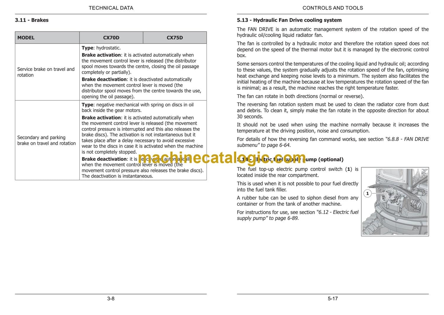
5.14 – Electric fuel supply pump (optional)……………………………………………………….. 5-17
5.15 – Geo-localisation system (optional)…………………………………………………………. 5-18
6 – USING THE MACHINE………………………………………………………………… 6-1
6.1 – Commissioning………………………………………………………………………………………6-1
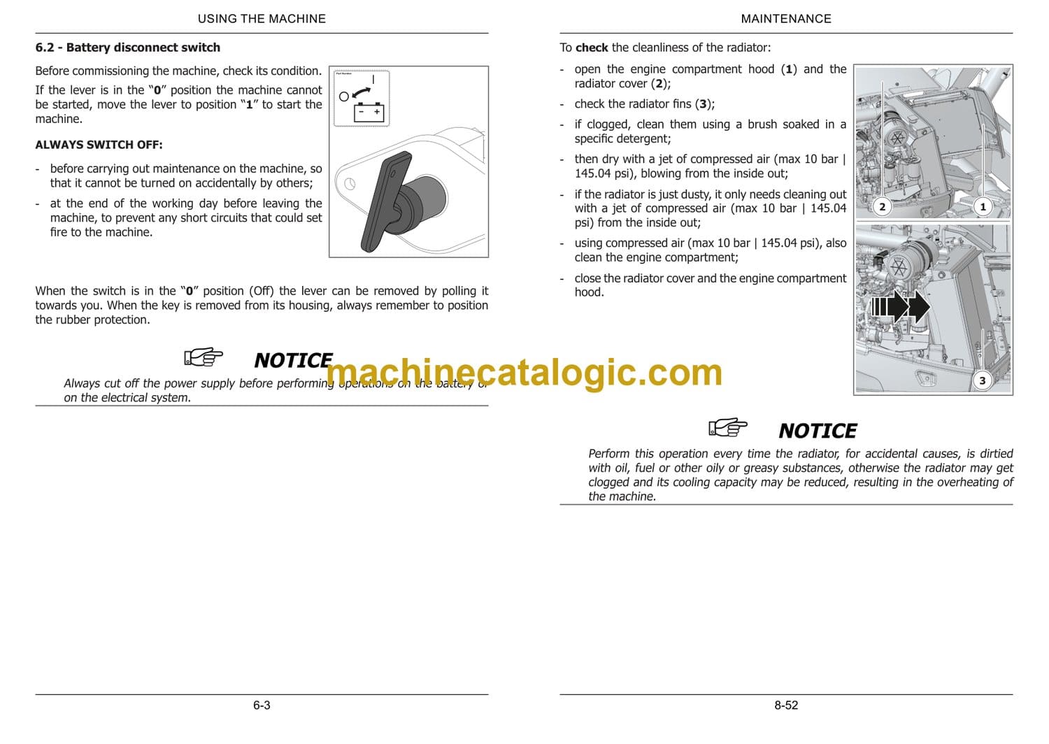
6.2 – Battery disconnect switch………………………………………………………………………… 6-3
6.3 – Driver seat…………………………………………………………………………………………… 6-4
6.4 – Pneumatic driver’s seat (optional)……………………………………………………………. 6-10
6.5 – Seat belt……………………………………………………………………………………………. 6-16
6.6 – Controls cut-out lever…………………………………………………………………………… 6-16
6.7 – Driving Cab………………………………………………………………………………………… 6-16
6.7.1 – Entering and leaving the driving cab…………………………………………………………… 6-17
6.7.2 – Courtesy light………………………………………………………………………………………… 6-19
6.7.3 – USB socket inside the cab………………………………………………………………………… 6-19
6.7.4 – Auxiliary socket outside the cab…………………………………………………………………. 6-20
6.7.5 – Windshield wiper……………………………………………………………………………………. 6-20
6.7.6 – Water container for windshield wiper………………………………………………………….. 6-21
6.7.7 – Opening the windshield……………………………………………………………………………. 6-21
6.7.8 – Opening the lower front glass……………………………………………………………………. 6-23
6.7.9 – Opening the right side window………………………………………………………………….. 6-24
6.7.10 – Opening the front protection grid……………………………………………………………… 6-24
6.7.11 – Hammer for emergency exit……………………………………………………………………. 6-25
6.7.12 – Sun shade…………………………………………………………………………………………… 6-26
6.7.13 – Cab ventilation system…………………………………………………………………………… 6-26
6.8 – Control panel operation…………………………………………………………………………. 6-29
6.8.1 – Dashboard to scroll through the menu on the display……………………………………… 6-30
6.8.2 – Home page…………………………………………………………………………………………… 6-32
6.8.2.1 – Time…………………………………………………………………………………………………. 6-33
6.8.2.2 – Electronic pump management………………………………………………………………… 6-33
6.8.2.3 – DPF filter management…………………………………………………………………………. 6-36
6.8.2.4 – Area dedicated to rear camera and messaging……………………………………………. 6-37
6.8.2.5 – Engine speed……………………………………………………………………………………… 6-39
6.8.2.6 – Machine hours and maintenance……………………………………………………………… 6-39
6.8.2.7 – Cab ventilation function…………………………………………………………………………. 6-40
6.8.3 – CAB VENTILATION page………………………………………………………………………….. 6-41
6.8.4 – MENU screen………………………………………………………………………………………… 6-44
6.8.5 – DISPLAY page……………………………………………………………………………………….. 6-45
6.8.5.1 – DISPLAY DATA submenu……………………………………………………………………….. 6-46
6.8.5.2 – REAR CAMERA submenu (if provided)………………………………………………………. 6-48
6.8.5.3 – QUICK ACCESS KEY F3 submenu…………………………………………………………….. 6-49
6.8.5.4 – LANGUAGE sub-menu…………………………………………………………………………… 6-50
6.8.5.5 – BRIGHTNESS submenu…………………………………………………………………………. 6-50
6.8.5.6 – DATE AND TIME submenu……………………………………………………………………… 6-51
6.8.5.7 – SOFTWARE submenu……………………………………………………………………………. 6-51
6.8.5.8 – UNITS OF MEASUREMENT sub-menu……………………………………………………….. 6-52
6.8.6 – EQUIPMENT screen………………………………………………………………………………… 6-52
6.8.6.1 – EQUIPMENT SELECTION submenu…………………………………………………………… 6-53
6.8.6.2 – EQUIPMENT RANGE SET-UP submenu………………………………………………………. 6-54
6.8.6.3 – EQUIPMENT SENSITIVITY SET-UP submenu………………………………………………. 6-55
6.8.6.4 – ELECTRO-PROPORTIONAL CONTROL/EQUIPMENT RESET submenu………………… 6-56
6.8.7 – SETTINGS screen…………………………………………………………………………………… 6-57
6.8.7.1 – GENERAL submenu………………………………………………………………………………. 6-58
6.8.7.2 – ELECTRO-PROPORTIONAL CONTROLS SET-UP submenu………………………………. 6-62
6.8.8 – FAN DRIVE submenu………………………………………………………………………………. 6-64
6.8.9 – REXROTH SETTINGS screen……………………………………………………………………… 6-68
6.8.9.1 – MULCHER SYSTEM sub-menu (optional)……………………………………………………. 6-70
6.8.10 – SERVICE screen……………………………………………………………………………………. 6-71
6.8.11 – AIR CONDITIONING page………………………………………………………………………. 6-71
6.9 – Visibility…………………………………………………………………………………………….. 6-72
6.9.1 – Travel position……………………………………………………………………………………….. 6-72
6.9.2 – Adjustment of rear-view mirrors and rear camera………………………………………….. 6-75
6.10 – Starting the engine…………………………………………………………………………….. 6-78
6.10.1 – Checks prior to the start up…………………………………………………………………….. 6-78
6.10.2 – Procedure for starting the machine…………………………………………………………… 6-80
6.11 – Start-up procedure with electric immobiliser (optional)……………………………….. 6-88
6.12 – Electric fuel supply pump…………………………………………………………………….. 6-89
6.13 – Engine jump-starting procedure…………………………………………………………….. 6-92
6.13.1 – Connecting the additional cables………………………………………………………………. 6-94
6.13.2 – Starting the engine……………………………………………………………………………….. 6-94
6.13.3 – Removing the additional cables………………………………………………………………… 6-95
6.14 – Horn……………………………………………………………………………………………….. 6-96
6.15 – Work lights……………………………………………………………………………………….. 6-96
6.16 – Operation at low temperatures or during winter………………………………………… 6-97
6.17 – Precautions during operation………………………………………………………………… 6-98
6.18 – Stopping and parking the machine……………………………………………………….. 6-101
6.19 – Refuelling……………………………………………………………………………………….. 6-103
6.19.1 – Refuelling with the electric pump……………………………………………………………. 6-103
6.20 – Accelerator hand grip………………………………………………………………………… 6-104
6.20.1 – Minimum automatic…………………………………………………………………………….. 6-105
6.21 – Machine movement………………………………………………………………………….. 6-107
6.21.1 – Forward and reverse travel……………………………………………………………………. 6-109
6.21.2 – Pivoting the machine around its axis……………………………………………………….. 6-110
6.21.3 – Turning while moving forward……………………………………………………………….. 6-111
6.21.4 – Turning while reversing………………………………………………………………………… 6-112
6.21.5 – Precautions during the operation of the tracks…………………………………………… 6-113
6.22 – Travel speed……………………………………………………………………………………. 6-115
6.23 – Dozer blade control………………………………………………………………………….. 6-116
6.24 – Dozer blade floating command (optional)………………………………………………. 6-117
6.25 – Boom movement……………………………………………………………………………… 6-118
6.25.1 – Left joystick………………………………………………………………………………………. 6-119
6.25.2 – Right joystick…………………………………………………………………………………….. 6-120
6.25.3 – TPSS Valve ISO-SAE (optional) control layout …………………………………………… 6-121
6.26 – Boom swing control………………………………………………………………………….. 6-123
6.27 – Triple positioner control (CX75D)…………………………………………………………. 6-125
6.28 – Discharge residual pressure in the hydraulic system…………………………………. 6-127
6.29 – Auxiliary hydraulic systems…………………………………………………………………. 6-128
6.29.1 – Connection of equipment to the hydraulic systems……………………………………… 6-130
6.29.2 – Operation of the taps on the second boom……………………………………………….. 6-132
6.29.3 – AUX1 Auxiliary hydraulic system…………………………………………………………….. 6-133
6.29.3.1 – AUX1 hydraulic system three-way switch……………………………………………….. 6-134
6.29.3.2 – Single-acting mode AUX1…………………………………………………………………… 6-136
6.29.3.3 – Double-acting mode AUX1………………………………………………………………….. 6-137
6.29.3.4 – Mechanical adjustment of maximum AUX1 system flow rate (58ZT only)……….. 6-138
6.29.3.5 – Mulcher mode with additional AUX1 system pump (optional)……………………… 6-140
6.29.4 – “D” button to reverse AUX2/AUX3 controls……………………………………………….. 6-142
6.29.5 – Auxiliary hydraulic system AUX2…………………………………………………………….. 6-143
6.29.6 – Auxiliary hydraulic system AUX3 (optional)……………………………………………….. 6-145
6.29.7 – Mechanical AUX3 auxiliary hydraulic system (optional)………………………………… 6-147
6.29.8 – Drainage line (direct to tank)…………………………………………………………………. 6-148
6.30 – Emergency lifting-boom lowering procedure…………………………………………… 6-149
6.31 – Using the DPF Diesel Particulate Filter and Regeneration…………………………… 6-150
6.31.1 – Regeneration……………………………………………………………………………………… 6-151
6.31.2 – Message/Alarm on the display for DPF…………………………………………………….. 6-152
6.31.3 – DPF clogging level………………………………………………………………………………. 6-154
6.31.4 – STATIONARY Regeneration……………………………………………………………………. 6-162
6.31.5 – Ash level…………………………………………………………………………………………… 6-164
6.32 – Procedure for installing and removing the supplementary counterweight………. 6-164
6.32.1 – Supplementary counterweight……………………………………………………………….. 6-164
6.33 – Daily storage…………………………………………………………………………………… 6-166
7 – RECOMMENDED OPTIONAL EQUIPMENT……………………………………… 7-1
7.1 – Safety precautions…………………………………………………………………………………. 7-2
7.1.1 – Specifications on authorised equipment…………………………………………………………. 7-4
7.2 – Equipment with standard coupling (pins)……………………………………………………..7-6
7.2.1 – Installation and removal…………………………………………………………………………….. 7-7
7.3 – Quick-coupling………………………………………………………………………………………. 7-8
7.3.1 – Set-up for hydraulic quick-coupling………………………………………………………………. 7-9
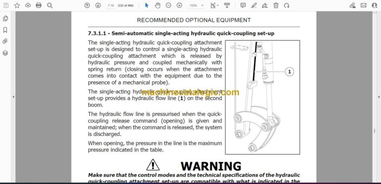
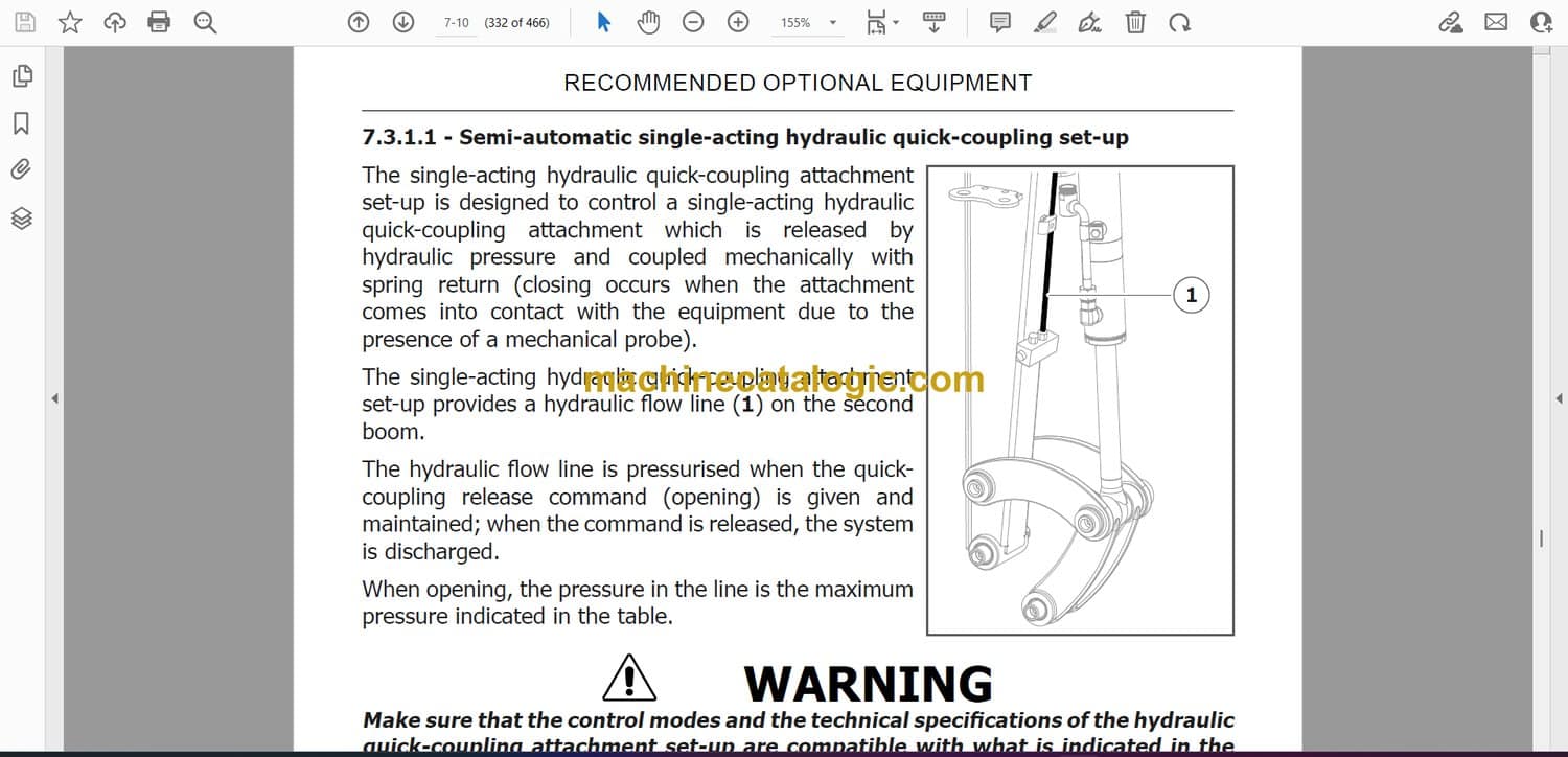
7.3.1.1 – Semi-automatic single-acting hydraulic quick-coupling set-up…………………………. 7-10
7.3.1.2 – Double-acting hydraulic quick coupling attachment set-up…………………………….. 7-11
7.3.1.3 – Single-acting valve maximum pressure adjustment………………………………………. 7-13
7.3.1.4 – Single adjustment double-acting valve maximum pressure adjustment…………….. 7-14
7.3.1.5 – Double adjustment double-acting valve maximum pressure adjustment……………. 7-15
7.3.2 – Hydraulic quick-coupling attachment…………………………………………………………… 7-17
7.3.2.1 – Semi-automatic single-acting hydraulic quick-coupling………………………………….. 7-18
7.3.2.2 – Double-acting hydraulic quick-coupling attachment………………………………………. 7-21
7.4 – Demolition hammer……………………………………………………………………………… 7-25
7.4.1 – Installation and removal…………………………………………………………………………… 7-25
7.4.2 – Precautions for use…………………………………………………………………………………. 7-25
7.4.3 – Operation……………………………………………………………………………………………… 7-28
7.5 – Mulcher…………………………………………………………………………………………….. 7-29
7.5.1 – Installation and removal…………………………………………………………………………… 7-30
7.6 – Material handling grapple………………………………………………………………………. 7-30
7.6.1 – Installation and removal…………………………………………………………………………… 7-31
7.6.2 – Operation……………………………………………………………………………………………… 7-31
7.7 – Auger……………………………………………………………………………………………….. 7-31
7.7.1 – Installation and removal…………………………………………………………………………… 7-31
7.7.2 – Operation……………………………………………………………………………………………… 7-31
7.8 – Hydraulic thumb………………………………………………………………………………….. 7-32
7.8.1 – Installation and removal…………………………………………………………………………… 7-33
7.8.2 – Precautions for use…………………………………………………………………………………. 7-33
7.8.3 – Operation……………………………………………………………………………………………… 7-36
7.8.4 – Lubrication……………………………………………………………………………………………. 7-36
7.9 – Load handling…………………………………………………………………………………….. 7-37
7.9.1 – Load handling table………………………………………………………………………………… 7-41
7.9.2 – Safety valves…………………………………………………………………………………………. 7-43
8 – MAINTENANCE………………………………………………………………………….. 8-1
8.1 – Safety………………………………………………………………………………………………….8-2
8.1.1 – Placement out of service for maintenance……………………………………………………… 8-5
8.1.2 – Engine start inhibition switch………………………………………………………………………. 8-6
8.2 – Tools and equipment for maintenance…………………………………………………………8-7
8.3 – Guards………………………………………………………………………………………………..8-8
8.3.1 – Engine hood…………………………………………………………………………………………… 8-9
8.3.2 – Radiator cover……………………………………………………………………………………….. 8-10
8.3.3 – Rear cover……………………………………………………………………………………………. 8-11
8.3.4 – Distributor compartment guard…………………………………………………………………. 8-12
8.3.5 – Fuse and relay compartment guard……………………………………………………………. 8-12
8.3.6 – Tool compartment guard………………………………………………………………………….. 8-13
8.4 – Protective structure tip-over…………………………………………………………………… 8-13
8.5 – Electrical system…………………………………………………………………………………. 8-16
8.6 – Tracks………………………………………………………………………………………………. 8-16
8.7 – Refilling…………………………………………………………………………………………….. 8-17
8.7.1 – Refilling quantity table…………………………………………………………………………….. 8-17
8.7.2 – Products for lubrication……………………………………………………………………………. 8-19
8.7.3 – Fuel…………………………………………………………………………………………………….. 8-20
8.7.4 – Engine oil……………………………………………………………………………………………… 8-21
8.7.5 – Cooling liquid………………………………………………………………………………………… 8-22
8.7.6 – Hydraulic system oil………………………………………………………………………………… 8-24
8.7.6.1 – Requirements for using eco-friendly hydraulic oil…………………………………………. 8-26
8.7.6.2 – Scheduled plan for analysis and control of ecological hydraulic oil……………………. 8-28
8.7.6.3 – Requirements for the sampling of eco-friendly hydraulic oil……………………………. 8-29
8.8 – Battery……………………………………………………………………………………………… 8-32
8.8.1 – Fitting and removing the battery……………………………………………………………….. 8-33
8.8.2 – Recharging the battery……………………………………………………………………………. 8-34
8.9 – Tightening torque tables……………………………………………………………………….. 8-35
8.10 – Periodic maintenance………………………………………………………………………….. 8-36
8.10.1 – Performance check……………………………………………………………………………….. 8-38
8.10.2 – Check of engine oil level………………………………………………………………………… 8-38
8.10.3 – Changing the engine oil…………………………………………………………………………. 8-40
8.10.4 – Changing the engine oil filter…………………………………………………………………… 8-42
8.10.5 – Replacement of oil separator filter……………………………………………………………. 8-44
8.10.6 – Check of cooling liquid level……………………………………………………………………. 8-46
8.10.7 – Changing the cooling liquid…………………………………………………………………….. 8-48
8.10.8 – Check and replacement of cooling liquid sleeves………………………………………….. 8-50
8.10.9 – Cleaning the radiator…………………………………………………………………………….. 8-51
8.10.10 – Cleaning the air conditioner condenser…………………………………………………….. 8-53
8.10.11 – Check the hydraulic oil level…………………………………………………………………… 8-54
8.10.12 – Change discharge circuit hydraulic oil filter……………………………………………….. 8-56
8.10.13 – Hydraulic system oil sampling/replacement……………………………………………….. 8-58
8.10.14 – Replacement of intake circuit hydraulic oil filter………………………………………….. 8-60
8.10.15 – Check the condition of hydraulic lines………………………………………………………. 8-62
8.10.16 – Check that the screws of the drive wheel/rollers are tight…………………………….. 8-63
8.10.17 – Track service position…………………………………………………………………………… 8-64
8.10.18 – Track tension check…………………………………………………………………………….. 8-66
8.10.19 – Adjusting the track tension……………………………………………………………………. 8-68
8.10.20 – Checking the tension and replacing the air conditioner belt…………………………… 8-71
8.10.21 – Checking tension and replacing alternator belt…………………………………………… 8-72
8.10.22 – Checking and replacing the air filter………………………………………………………… 8-73
8.10.23 – Checking for clogging cab ventilation system air filter replacement…………………. 8-75
8.10.24 – Replacement of fuel filter……………………………………………………………………… 8-77
8.10.25 – Draining the fuel tank………………………………………………………………………….. 8-78
8.10.26 – Draining water from the fuel circuit…………………………………………………………. 8-79
8.10.27 – Cleaning the filter on the fuel intake………………………………………………………… 8-80
8.10.28 – Bleeding air from the fuel circuit…………………………………………………………….. 8-82
8.10.29 – Level control and replacement of geared motors translation oil……………………… 8-84
8.10.30 – Swivel geared motor……………………………………………………………………………. 8-85
8.10.31 – Lubrication of pins………………………………………………………………………………. 8-86
8.11 – Long inactivity periods………………………………………………………………………… 8-88
8.12 – Dismantling the machine……………………………………………………………………… 8-90
9 – ELECTRICAL COMPONENTS………………………………………………………… 9-1
9.1 – Fuses and relays…………………………………………………………………………………… 9-1
9.1.1 – Control box fuses…………………………………………………………………………………….. 9-2
9.1.2 – Engine fuses and relays…………………………………………………………………………….. 9-6
9.2 – Work lights replacement…………………………………………………………………………. 9-7
9.3 – LED strip replacement…………………………………………………………………………….. 9-8


