Format: PDF (Printable Document)
File Language: English
File Pages: 604
File Size: 54.53 MB (Speed Download Link)
Brand: Case
Model: True-Tandem 345 22-34 Foot Disk Harrow
Part No: 92318830
Date: December 2024
Type of Document: Assembly Instructions
$ 45
1 SAFETY INFORMATION
Personal safety . . . . . . . . . . . . . . . . . . . . . . . . . . . . . . . . . . . . . . . . . . . . . . . . . . . . . . . . . . . . . . . . . . . . . . . . . . . . . 1-1
General information and safety. . . . . . . . . . . . . . . . . . . . . . . . . . . . . . . . . . . . . . . . . . . . . . . . . . . . . . . . . . . . . 1-3
2 GENERAL INFORMATION
Product overview . . . . . . . . . . . . . . . . . . . . . . . . . . . . . . . . . . . . . . . . . . . . . . . . . . . . . . . . . . . . . . . . . . . . . . . . . . . 2-1
Torque . . . . . . . . . . . . . . . . . . . . . . . . . . . . . . . . . . . . . . . . . . . . . . . . . . . . . . . . . . . . . . . . . . . . . . . . . . . . . . . . . . . . . . 2-4
Special bolt torque. . . . . . . . . . . . . . . . . . . . . . . . . . . . . . . . . . . . . . . . . . . . . . . . . . . . . . . . . . . . . . . . . . . . . . . . . . 2-9
Torque – Standard torque data for hydraulic connections . . . . . . . . . . . . . . . . . . . . . . . . . . . . . . . . . 2-10
Soil preparation/Finishing – Basic instructions. . . . . . . . . . . . . . . . . . . . . . . . . . . . . . . . . . . . . . . . . . . . . 2-17
Attaching the implement to the tractor. . . . . . . . . . . . . . . . . . . . . . . . . . . . . . . . . . . . . . . . . . . . . . . . . . . . . 2-18
Hydraulic hose connections – Standard frame control. . . . . . . . . . . . . . . . . . . . . . . . . . . . . . . . . . . . . 2-24
Hydraulic hose connections – Electronic frame control . . . . . . . . . . . . . . . . . . . . . . . . . . . . . . . . . . . . 2-26
3 PRE-ASSEMBLY
PREPARING FOR ASSEMBLY
Required building and equipment . . . . . . . . . . . . . . . . . . . . . . . . . . . . . . . . . . . . . . . . . . . . . . . . . . . . . . 3-1
Shipping package configurations . . . . . . . . . . . . . . . . . . . . . . . . . . . . . . . . . . . . . . . . . . . . . . . . . . . . . . . 3-2
Unpacking safety . . . . . . . . . . . . . . . . . . . . . . . . . . . . . . . . . . . . . . . . . . . . . . . . . . . . . . . . . . . . . . . . . . . . . . . 3-4
Unpacking the shipping packages. . . . . . . . . . . . . . . . . . . . . . . . . . . . . . . . . . . . . . . . . . . . . . . . . . . . . . 3-5
Removing the shipping brackets . . . . . . . . . . . . . . . . . . . . . . . . . . . . . . . . . . . . . . . . . . . . . . . . . . . . . . . 3-6
Unpacking one-piece main frame and pull frame . . . . . . . . . . . . . . . . . . . . . . . . . . . . . . . . . . . . . . 3-7
4 ASSEMBLY
ASSEMBLY
Before assembly. . . . . . . . . . . . . . . . . . . . . . . . . . . . . . . . . . . . . . . . . . . . . . . . . . . . . . . . . . . . . . . . . . . . 4-1
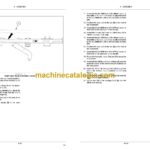
Main frame assembly. . . . . . . . . . . . . . . . . . . . . . . . . . . . . . . . . . . . . . . . . . . . . . . . . . . . . . . . . . . . . . . 4-2
Universal Control Module (UCM) installation – Electronic frame control . . . . . . . . . . . 4-3
Main lift valve block assembly to main frame – Electronic frame control . . . . . . . . . . . 4-9
Transport hub and spindle installation. . . . . . . . . . . . . . . . . . . . . . . . . . . . . . . . . . . . . . . . . . . . . 4-16
Main frame lift cylinder installation – Standard frame control . . . . . . . . . . . . . . . . . . . . . . 4-18
Main frame lift cylinder installation – Electronic frame control . . . . . . . . . . . . . . . . . . . . . 4-22
Center shank assembly . . . . . . . . . . . . . . . . . . . . . . . . . . . . . . . . . . . . . . . . . . . . . . . . . . . . . . . . . . . 4-26
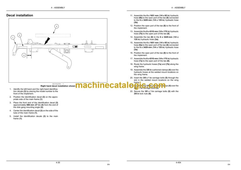
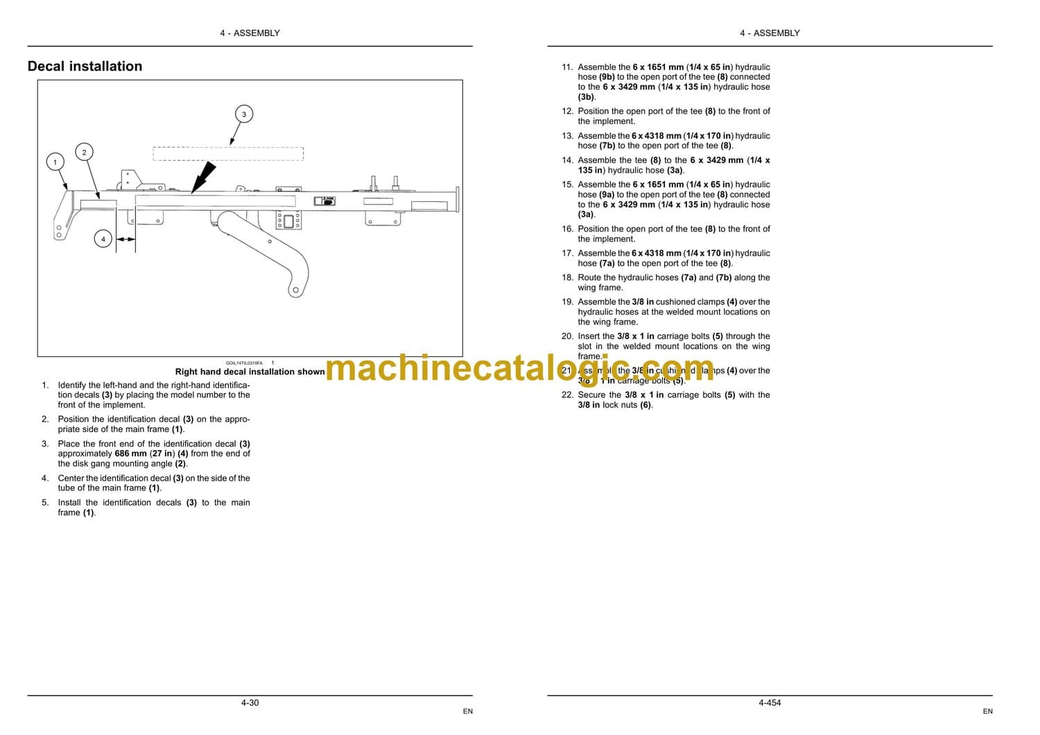
Decal installation . . . . . . . . . . . . . . . . . . . . . . . . . . . . . . . . . . . . . . . . . . . . . . . . . . . . . . . . . . . . . . . . . . 4-30
Small and medium main frame disk gang installation . . . . . . . . . . . . . . . . . . . . . . . . . . . . . 4-32
Large main frame disk gang installation. . . . . . . . . . . . . . . . . . . . . . . . . . . . . . . . . . . . . . . . . . . 4-35
191 mm (7-1/2 in) cushion main frame disk gang identification . . . . . . . . . . . . . . . . . . . 4-40
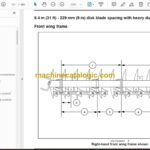
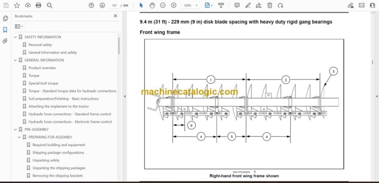
229 mm (9 in) cushion main frame disk gang identification . . . . . . . . . . . . . . . . . . . . . . . 4-46
191 mm (7-1/2 in) rigid main frame disk gang identification. . . . . . . . . . . . . . . . . . . . . . . 4-54
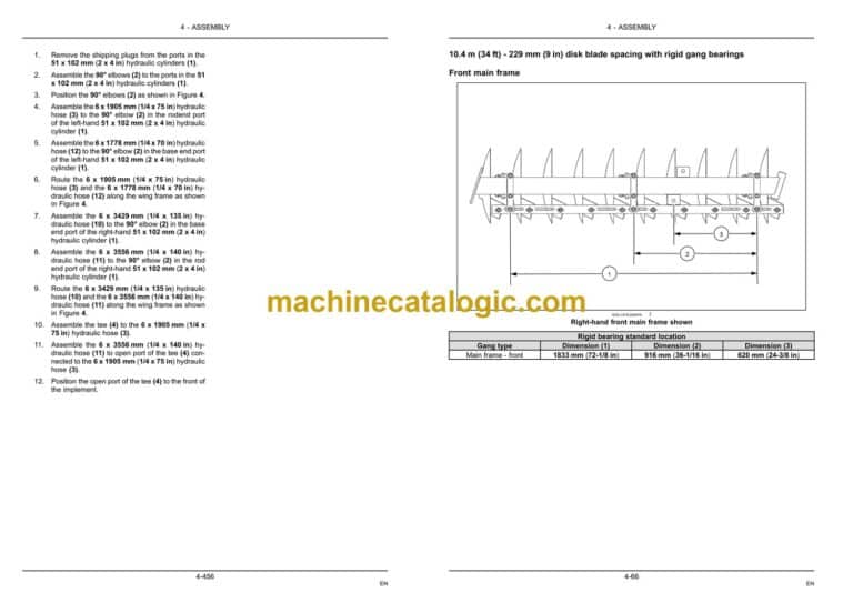
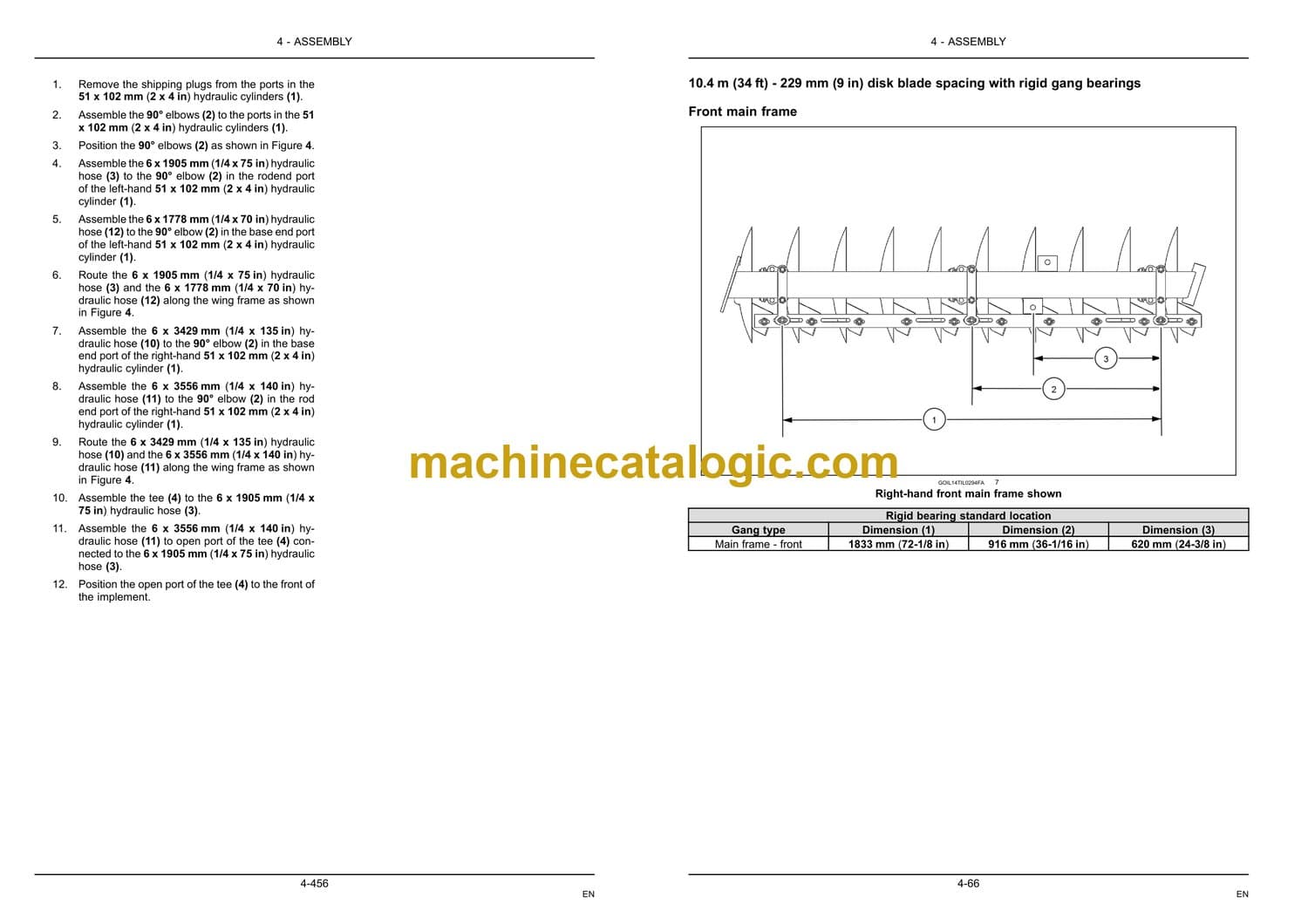
229 mm (9 in) rigid main frame disk blade identification . . . . . . . . . . . . . . . . . . . . . . . . . . 4-60
Wing frame to main frame assembly . . . . . . . . . . . . . . . . . . . . . . . . . . . . . . . . . . . . . . . . . . . . . . 4-68
191 mm (7-1/2 in) cushion wing frame disk gang identification . . . . . . . . . . . . . . . . . . . 4-70
229 mm (9 in) cushion wing frame disk gang identification . . . . . . . . . . . . . . . . . . . . . . . 4-84
191 mm (7-1/2 in) rigid wing frame disk gang identification . . . . . . . . . . . . . . . . . . . . . . . 4-98
229 mm (9 in) rigid wing frame disk gang identification . . . . . . . . . . . . . . . . . . . . . . . . . . 4-112
Wheel pedestals to wing frame assembly . . . . . . . . . . . . . . . . . . . . . . . . . . . . . . . . . . . . . . . . 4-126
Wing frame eye bolt installation . . . . . . . . . . . . . . . . . . . . . . . . . . . . . . . . . . . . . . . . . . . . . . . . . . 4-129
Wing frame lift cylinder installation – Standard frame control. . . . . . . . . . . . . . . . . . . . . 4-131
Wing frame lift cylinder installation – Electronic frame control . . . . . . . . . . . . . . . . . . . . 4-135
6.7 – 9.4 m (22 – 31 ft) wing stop installation . . . . . . . . . . . . . . . . . . . . . . . . . . . . . . . . . . . . . 4-139
10.4 m (34 ft) wing stop installation . . . . . . . . . . . . . . . . . . . . . . . . . . . . . . . . . . . . . . . . . . . . . . 4-143
Spring leveling link assembly installation. . . . . . . . . . . . . . . . . . . . . . . . . . . . . . . . . . . . . . . . . 4-146
Single Point Depth Control (SPDC) assembly . . . . . . . . . . . . . . . . . . . . . . . . . . . . . . . . . . . 4-149
Single basket down pressure valve block installation – Electronic frame control . 4-154
Pull frame to main frame assembly. . . . . . . . . . . . . . . . . . . . . . . . . . . . . . . . . . . . . . . . . . . . . . . 4-157
Jack installation. . . . . . . . . . . . . . . . . . . . . . . . . . . . . . . . . . . . . . . . . . . . . . . . . . . . . . . . . . . . . . . . . . . 4-164
Swinging hose boom to pull frame assembly. . . . . . . . . . . . . . . . . . . . . . . . . . . . . . . . . . . . . 4-165
Auxiliary valve block installation to pull frame – Electronic frame control. . . . . . . . . 4-167
Pull frame leveling – turnbuckle assembly . . . . . . . . . . . . . . . . . . . . . . . . . . . . . . . . . . . . . . . . 4-173
Fore/aft cylinder hydraulic fitting and hose assembly – Standard frame control. . 4-175
Fore/aft cylinder hydraulic fitting and hose assembly – Electronic frame control . 4-186
Main frame and wing frame lift hydraulic hose installation – Standard frame control4-192
Main frame and wing frame lift hydraulic hose installation – Electronic frame control
. . . . . . . . . . . . . . . . . . . . . . . . . . . . . . . . . . . . . . . . . . . . . . . . . . . . . . . . . . . . . . . . . . . . . . . . . . . . . . . . 4-231
Hydraulic hose bracket assembly . . . . . . . . . . . . . . . . . . . . . . . . . . . . . . . . . . . . . . . . . . . . . . . . 4-249
Single Point Depth Control (SPDC) hydraulic hose installation – Electronic frame control
. . . . . . . . . . . . . . . . . . . . . . . . . . . . . . . . . . . . . . . . . . . . . . . . . . . . . . . . . . . . . . . . . . . . . . . . . . . . . . . . 4-252
Main lift valve block to auxiliary valve block hydraulic hose connections – Electronic
frame control . . . . . . . . . . . . . . . . . . . . . . . . . . . . . . . . . . . . . . . . . . . . . . . . . . . . . . . . . . . . . . . . . . . . . 4-258
Auxiliary valve block to tractor hydraulic hose connections – Electronic frame control
. . . . . . . . . . . . . . . . . . . . . . . . . . . . . . . . . . . . . . . . . . . . . . . . . . . . . . . . . . . . . . . . . . . . . . . . . . . . . . . . 4-262
Wing fold hydraulics . . . . . . . . . . . . . . . . . . . . . . . . . . . . . . . . . . . . . . . . . . . . . . . . . . . . . . . . . . . . . . 4-266
Hydraulic hose identification tags – Standard frame control . . . . . . . . . . . . . . . . . . . . . . 4-287
Hydraulic hose identification tags – Electronic frame control . . . . . . . . . . . . . . . . . . . . . 4-289
Warning light and tail light installation . . . . . . . . . . . . . . . . . . . . . . . . . . . . . . . . . . . . . . . . . . . . 4-291
Red tail/stop light bracket assembly. . . . . . . . . . . . . . . . . . . . . . . . . . . . . . . . . . . . . . . . . . . . . . 4-295
Amber hazard light bracket assembly . . . . . . . . . . . . . . . . . . . . . . . . . . . . . . . . . . . . . . . . . . . . 4-297
Slow-Moving Vehicle (SMV) bracket and sign assembly . . . . . . . . . . . . . . . . . . . . . . . . . 4-299
Safety lighting installation . . . . . . . . . . . . . . . . . . . . . . . . . . . . . . . . . . . . . . . . . . . . . . . . . . . . . . . . 4-301
6.7 m (22 ft) and 7.6 m (25 ft) implements . . . . . . . . . . . . . . . . . . . . . . . . . . . 4-301
8.5 m (28 ft) and 9.4 m (31 ft) implements . . . . . . . . . . . . . . . . . . . . . . . . . . . 4-305
10.4 m (34 ft) implements . . . . . . . . . . . . . . . . . . . . . . . . . . . . . . . . . . . . . . . . . . . . 4-310
Wiring harness installation – Electronic frame control . . . . . . . . . . . . . . . . . . . . . . . . . . . . 4-317
Wiring harness cable tie installation . . . . . . . . . . . . . . . . . . . . . . . . . . . . . . . . . . . . . . . . . . . . . . 4-327
Optional pivoting stabilizer wheel. . . . . . . . . . . . . . . . . . . . . . . . . . . . . . . . . . . . . . . . . . . . . . . . . 4-329
Single roller basket frame attachment tubes . . . . . . . . . . . . . . . . . . . . . . . . . . . . . . . . . . . . . 4-333
Installation for 6.7 – 7.6 m (22 – 25 ft) implements . . . . . . . . . . . . . . . . . . 4-333
Installation for 8.5 – 9.4 m (28 – 31 ft) implements . . . . . . . . . . . . . . . . . . 4-337
Installation for 10.4 m (34 ft) implement. . . . . . . . . . . . . . . . . . . . . . . . . . . . . . 4-341
