Format: PDF (Printable Document)
File Language: English
File Pages: 108
File Size: 10.00 MB (Speed Download Link)
Brand: Case
Model: Vibra-Tine 265 Single Fold Field Cultivator
Part No: 90410123
Date: December 2020
Type of Document: Assembly Instructions
$ 45
Out in the field, this Vibra-Tine 265 single fold cultivator is doing seedbed prep and weed control in worked ground, usually right behind a tractor in dusty, uneven conditions. This assembly instructions manual helps you put the machine together correctly the first time, so shanks, frames, and folding sections line up and run true. When you’ve just unloaded a new or rebuilt unit, or you’ve replaced a bent wing or frame piece, this is what you use to verify where each bracket, tine, and hydraulic component belongs, and how it all ties together so the tool pulls straight and works evenly across the field.
Applications & Use Cases
FAQ
Q: Is this manual useful if I bought the cultivator used and partially assembled?
A: Yes, it helps you confirm correct assembly, spot missing parts, and straighten out previous owner “customizing.”
Q: Can I keep a digital copy on my phone in the field?
A: Yes, many techs do that so they can zoom in on diagrams and double-check assemblies right beside the machine.
Safety Note
Always lock out hydraulics, support raised sections securely, and keep hands clear of pinch points during assembly.
SAFETY INFORMATION
Personal safety . . . . . . . . . . . . . . . . . . . . . . . . . . . . . . . . . . . . . . . . . . . . . . . . . . . . . . . . . . . . . . . . . . . . . . . . . . . . . 1-1
General information and safety. . . . . . . . . . . . . . . . . . . . . . . . . . . . . . . . . . . . . . . . . . . . . . . . . . . . . . . . . . . . . 1-2
2 GENERAL INFORMATION
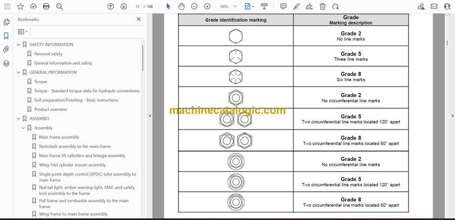
Torque . . . . . . . . . . . . . . . . . . . . . . . . . . . . . . . . . . . . . . . . . . . . . . . . . . . . . . . . . . . . . . . . . . . . . . . . . . . . . . . . . . . . . . 2-1
Torque – Standard torque data for hydraulic connections . . . . . . . . . . . . . . . . . . . . . . . . . . . . . . . . . . 2-6
Soil preparation/Finishing – Basic instructions. . . . . . . . . . . . . . . . . . . . . . . . . . . . . . . . . . . . . . . . . . . . . 2-13
Product overview . . . . . . . . . . . . . . . . . . . . . . . . . . . . . . . . . . . . . . . . . . . . . . . . . . . . . . . . . . . . . . . . . . . . . . . . . . 2-14
3 ASSEMBLY
Assembly
Main frame assembly. . . . . . . . . . . . . . . . . . . . . . . . . . . . . . . . . . . . . . . . . . . . . . . . . . . . . . . . . . . . . . . 3-1
Rockshaft assembly to the main frame. . . . . . . . . . . . . . . . . . . . . . . . . . . . . . . . . . . . . . . . . . . . . 3-2
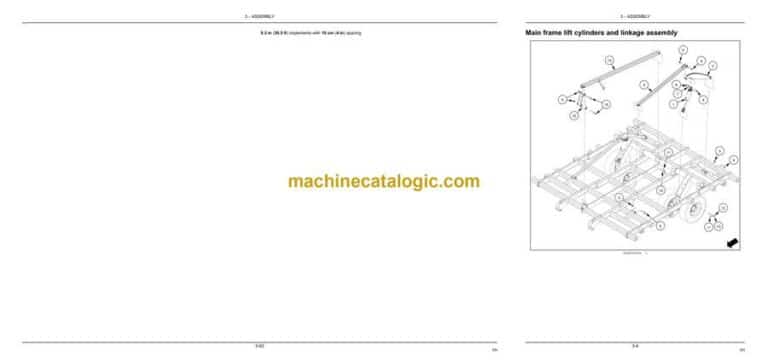
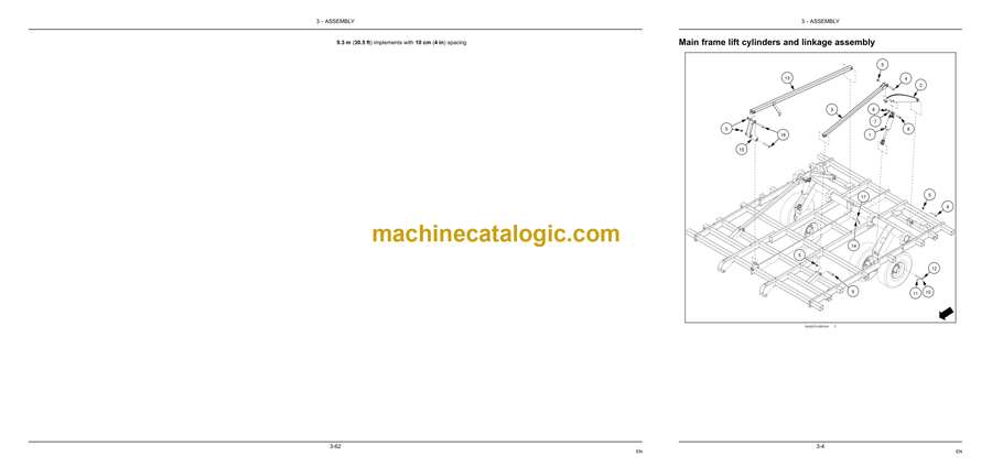
Main frame lift cylinders and linkage assembly. . . . . . . . . . . . . . . . . . . . . . . . . . . . . . . . . . . . . 3-4
Wing fold cylinder mount assembly . . . . . . . . . . . . . . . . . . . . . . . . . . . . . . . . . . . . . . . . . . . . . . . . 3-6
Single point depth control (SPDC) tube assembly to main frame . . . . . . . . . . . . . . . . . . 3-8
Red tail light, amber warning light, SMV, and safety lock assembly to the frame . 3-10
Pull frame and turnbuckle assembly to the main frame . . . . . . . . . . . . . . . . . . . . . . . . . . . 3-13
Wing frame to main frame assembly . . . . . . . . . . . . . . . . . . . . . . . . . . . . . . . . . . . . . . . . . . . . . . 3-16
Wing fold cylinder assembly. . . . . . . . . . . . . . . . . . . . . . . . . . . . . . . . . . . . . . . . . . . . . . . . . . . . . . . 3-18
Wing frame rockshaft assembly . . . . . . . . . . . . . . . . . . . . . . . . . . . . . . . . . . . . . . . . . . . . . . . . . . . 3-20
Wing lift cylinder and linkage assembly . . . . . . . . . . . . . . . . . . . . . . . . . . . . . . . . . . . . . . . . . . . 3-22
Hydraulic tree assembly . . . . . . . . . . . . . . . . . . . . . . . . . . . . . . . . . . . . . . . . . . . . . . . . . . . . . . . . . . . 3-24
Hydraulics
Main frame and wing frame lift cylinder hydraulic hose installation – 8.1 m (26.5 ft)
implements . . . . . . . . . . . . . . . . . . . . . . . . . . . . . . . . . . . . . . . . . . . . . . . . . . . . . . . . . . . . . . . . . . . . . . . . 3-26
Main frame and wing frame lift cylinder hydraulic hose installation – 8.7 m (28.5 ft)
implements . . . . . . . . . . . . . . . . . . . . . . . . . . . . . . . . . . . . . . . . . . . . . . . . . . . . . . . . . . . . . . . . . . . . . . . . 3-31
Main frame and wing frame lift cylinder hydraulic hose installation – 9.3 m (30.5 ft)
implements . . . . . . . . . . . . . . . . . . . . . . . . . . . . . . . . . . . . . . . . . . . . . . . . . . . . . . . . . . . . . . . . . . . . . . . . 3-35
Main frame and wing frame lift cylinder hydraulic hose installation – 9.9 m (32.5 ft)
implements . . . . . . . . . . . . . . . . . . . . . . . . . . . . . . . . . . . . . . . . . . . . . . . . . . . . . . . . . . . . . . . . . . . . . . . . 3-39
Wing frame fold cylinder hydraulic hose installation. . . . . . . . . . . . . . . . . . . . . . . . . . . . . . . 3-43
Hydraulic hose routing Hydraulic hose routing . . . . . . . . . . . . . . . . . . . . . . . . . . . . . . . . . . . 3-47
Wiring harness installation . . . . . . . . . . . . . . . . . . . . . . . . . . . . . . . . . . . . . . . . . . . . . . . . . . . . . . . . 3-52
Tine spacing
Vibra-Tine assembly. . . . . . . . . . . . . . . . . . . . . . . . . . . . . . . . . . . . . . . . . . . . . . . . . . . . . . . . . . . . . . . 3-54
Measuring for the Vibra-Tine layouts . . . . . . . . . . . . . . . . . . . . . . . . . . . . . . . . . . . . . . . . . . . . . . 3-55
Vibra-Tine layout diagrams . . . . . . . . . . . . . . . . . . . . . . . . . . . . . . . . . . . . . . . . . . . . . . . . . . . . . . . . 3-56
Knock on sweep installation . . . . . . . . . . . . . . . . . . . . . . . . . . . . . . . . . . . . . . . . . . . . . . . . . . . . . . . 3-67
Optional kits
Pivoting stabilizer wheel installation . . . . . . . . . . . . . . . . . . . . . . . . . . . . . . . . . . . . . . . . . . . . . . . 3-69
Rear jack assembly. . . . . . . . . . . . . . . . . . . . . . . . . . . . . . . . . . . . . . . . . . . . . . . . . . . . . . . . . . . . . . . . 3-71
4 POST-ASSEMBLY
INSTRUCTIONS
Connecting the implement to the tractor . . . . . . . . . . . . . . . . . . . . . . . . . . . . . . . . . . . . . . . . . . . . . . . 4-1
Removing air from the hydraulic system . . . . . . . . . . . . . . . . . . . . . . . . . . . . . . . . . . . . . . . . . . . . . . . 4-4
FINAL-CHECK
Assembly checklist . . . . . . . . . . . . . . . . . . . . . . . . . . . . . . . . . . . . . . . . . . . . . . . . . . . . . . . . . . . . . . . . . . . . . 4-7

