Format: PDF (Printable Document)
File Language: English
File Pages: 104
File Size: 8.73 MB (Speed Download Link)
Brand: CNH
Model: P2060, Flex Hoe 700
Part No: STM5181B
Date: 01-2014
Type of Document: Service Training Manual
$ 45
Out in small grains or canola, the P2060/Flex Hoe 700 spends its life pulling through hard, sometimes wet ground, so wear, plugging, and hydraulic complaints are normal. This service training manual is what I’d use to understand how the opener, frame, and air delivery systems are supposed to work together before I ever grab a wrench. If, for example, one wing won’t follow depth while the rest of the drill is fine, this book helps me think through the hydraulic and mechanical interactions instead of just swapping parts.
Applications & Use Cases
FAQ
Q: Can I use this manual on a tablet in the field?
A: Yes, it’s well suited to digital use; you can zoom diagrams and search terms while you’re parked beside the drill.
Q: Is it still worth printing parts of it?
A: I’d print key schematics and theory pages to keep in the service truck for quick reference when there’s no signal.
Safety Note
Always verify the machine is fully lowered, supported, and hydraulically de-energized before you inspect or adjust any component.
FEATURES: ……………………………………………………………………………………………………………………….. 1
Fold back Design: ……………………………………………………………………………………………………………………………… 1
Design Features:……………………………………………………………………………………………………………………………….. 2
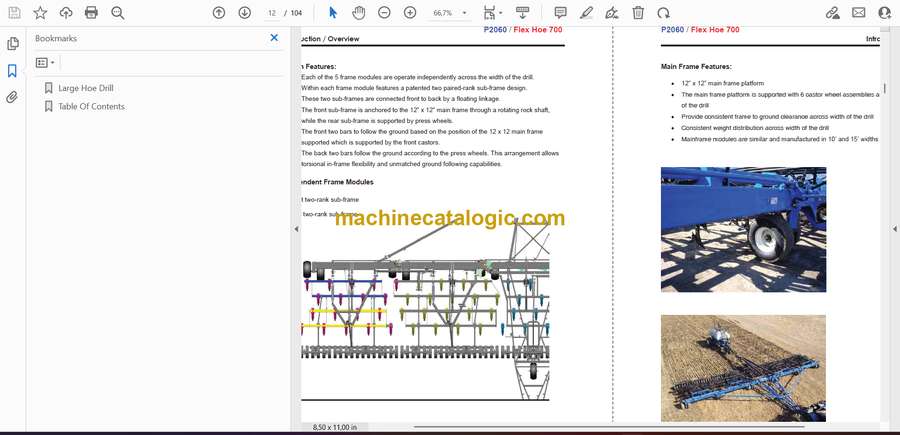
Independent Frame Modules …………………………………………………………………………………………………………….. 2
Main Frame Features: ……………………………………………………………………………………………………………………….. 3
RAISE/LOWER CYLINDER USED FOR INFIELD & TRANSPORT: ……………………………………………. 4
In-field Raise/Lowering of Toolbar ………………………………………………………………………………………………………. 4
Transport Fold/Unfold ………………………………………………………………………………………………………………………. 4
SINGLE POINT DEPTH SETTING: ………………………………………………………………………………………… 5
ADJUSTABLE PACKING PRESSURE: ………………………………………………………………………………….. 5
TRANSPORT TO FIELD POSITION: ……………………………………………………………………………………… 7
AIR CART FIELD HITCH: …………………………………………………………………………………………………….. 8
OPTIONAL AUXILIARY HITCH: ……………………………………………………………………………………………. 8
TRIP OPTIONS: ………………………………………………………………………………………………………………….. 9
350-Pound Trip ………………………………………………………………………………………………………………………………… 9
550-Pound Trip ………………………………………………………………………………………………………………………………… 9
Shank Mount ……………………………………………………………………………………………………………………………………. 9
Shank Options ………………………………………………………………………………………………………………………………….. 9
STEALTH™ OPENERS ……………………………………………………………………………………………………… 10
PACKER WHEEL OPTIONS; ………………………………………………………………………………………………. 11
Steel Press Wheels: …………………………………………………………………………………………………………………………. 11
Semi-pneumatic Rubber Press Wheels: ……………………………………………………………………………………………… 11
Pneumatic Rubber Press Wheels: ……………………………………………………………………………………………………… 11
Concord ™ Walking Beam, Pneumatic Wheel Packing System:……………………………………………………………… 12
Dry soil with a narrow seed band ……………………………………………………………………………………………………… 12
Wet soil with a narrow seed band or normal conditions with a wide seed band …………………………………….. 12
Very wet and sticky soil……………………………………………………………………………………………………………………. 12
Suitable openers include:…………………………………………………………………………………………………………………. 12
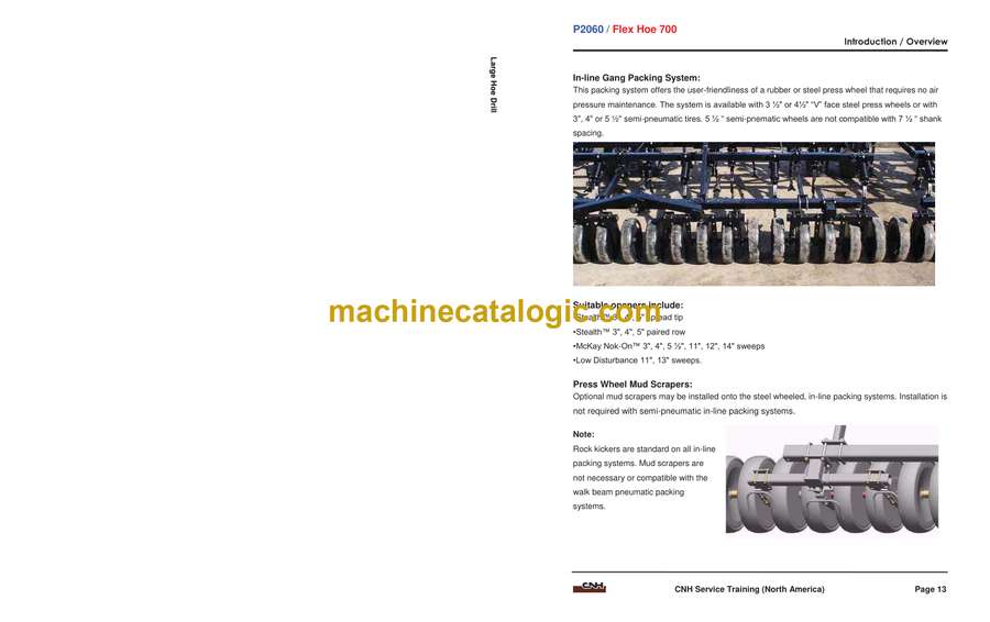
In-line Gang Packing System: ……………………………………………………………………………………………………………. 13
Suitable openers include:…………………………………………………………………………………………………………………. 13
Press Wheel Mud Scrapers: ……………………………………………………………………………………………………………… 13
OPTIONAL HARROWS AND LEVELERS ………………………………………………………………………………14
Single Bar Harrows ………………………………………………………………………………………………………………………….. 14
Shank-mounted Disk Levelers …………………………………………………………………………………………………………… 14
SPECIFICATIONS ……………………………………………………………………………………………………………..15
Weight …………………………………………………………………………………………………………………………………………… 17
TIRE PRESSURE ………………………………………………………………………………………………………………19
COMPONENTS …………………………………………………………………………………………………………………21
DYNAMIC DESCRIPTION MACHINE POSITIONS ………………………………………………………………….22
Field Position. …………………………………………………………………………………………………………………………………. 22
Headland Position. ………………………………………………………………………………………………………………………….. 22
Fully Raised Position. ……………………………………………………………………………………………………………………….. 22
Locked position. ……………………………………………………………………………………………………………………………… 22
Transport Position. ………………………………………………………………………………………………………………………….. 22
FRAME MONITORING FRAME POSITION SENSORS ……………………………………………………………23
Sensor state and Frame Position ……………………………………………………………………………………………………….. 23
FRAME MONITORING MESSAGES AND ALARMS ………………………………………………………………..24
AIR DRILL AND AIR CART CONNECTED ……………………………………………………………………………..24
MOVING FROM FIELD TO TRANSPORT POSITION ( STARTING AT SERIAL NUMBER
Y9S003001) ………………………………………………………………………………………………………………………26
MOVING FROM TRANSPORT TO FIELD POSITION (STARTING AT SERIAL NUMBER Y9S003001)
………………………………………………………………………………………………………………………………………..31
FRAME LEVELLING – HEIGHT ADJUST REAR FRAME SECTION …………………………………………..40
FRAME LEVELLING – Height adjust …………………………………………………………………………………………………….. 40
Check Rear section Side to Side Levelling …………………………………………………………………………………………… 40
FRAME LEVELLING – Height adjust Front to Back Levelling: …………………………………………………………………… 41
FRAME LEVELLING – Height adjust Center Section ……………………………………………………………………………….. 42
Height adjust Final Levelling and Field Check ……………………………………………………………………………………… 45
ADJUSTING PACKING PRESSURE …………………………………………………………………………………….46
ADJUST PACKER KICK-OUT CABLE ADJUSTMENT …………………………………………………………….47
CASTER WHEEL – TOE IN ADJUST LOCKING CASTER ALIGNMENT ……………………………………..48
ADJUST LOCKSHAFT ENGAGEMENT ADJUSTMENT BOLT ………………………………………………….49
ELECTRONIC SCHEMA FRAME MONITORING HARNESS …………………………………………………….51
For Tow Between Air Cart ………………………………………………………………………………………………………………… 51
Tow Behind Air Cart …………………………………………………………………………………………………………………………. 52
CLEARANCE SENSOR ADJUSTMENT ……………………………………………………………………………….. 58
Caster Trap Sensor ………………………………………………………………………………………………………………………….. 58
Lock Shaft Sensor ……………………………………………………………………………………………………………………………. 58
Draw Tube Sensor …………………………………………………………………………………………………………………………… 58
CHECK SEE WHAT’S CONNECTED …………………………………………………………………………………… 59
To See What’s Connected ………………………………………………………………………………………………………………… 59
CHECK SYSTEM VOLTAGES …………………………………………………………………………………………….. 60
CHECK SENSOR STATUS ………………………………………………………………………………………………… 61
SENSOR STATES …………………………………………………………………………………………………………….. 61
CHECK VIRTUAL TERMINAL …………………………………………………………………………………………….. 62
CHECK VERSION …………………………………………………………………………………………………………….. 63
FAULT CODES …………………………………………………………………………………………………………………. 64
Communcations Error @ LHDFM Remote1 ………………………………………………………………………………………… 64
Low Battery Voltage @ LHDFM Remote1 …………………………………………………………………………………………… 65
Open or short circuit , Lt. Lock Shaft Is Shorted or Open! …………………………………………………………………….. 66
HYDRAULIC SCHEMA FIELD POSITION …………………………………………………………………………….. 68
Field Position: Lowering Frames ……………………………………………………………………………………………………….. 70
Field Position: Raising frames …………………………………………………………………………………………………………… 71
Lock Shaft engaged: Right frames raising vertical ……………………………………………………………………………….. 72
Right frames vertical: Swing right boom back …………………………………………………………………………………….. 73
Right boom back: Raising left frames ………………………………………………………………………………………………… 74
Left frames vertical: Swing left wing back ………………………………………………………………………………………….. 75
Charging Hydraulic Run in and System Charging …………………………………………………………………………………. 76
HYDRAULIC SEQUENCE CHECKLIST………………………………………………………………………………… 81
SHIM INSTALLATION ………………………………………………………………………………………………………… 87
ANGLE ADJUST SWEEP PITCH ADJUSTMENT …………………………………………………………………… 88
To change the sweep angle ……………………………………………………………………………………………………………… 89
TRIP – COMPRESSOR TOOL KIT ……………………………………………………………………………………….. 90
TOOL PRESS WHEEL – REMOVE ……………………………………………………………………………………… 92


