Format: PDF (Printable Document)
File Language: English
File Pages: 728
File Size: 66.92 MB (Speed Download Link)
Brand: Clark
Model: C60, C70, C80 D and C80D900 Forklift
Book No: SM1328
Part No: 8186459
Type of Document: Service Manual
$ 40
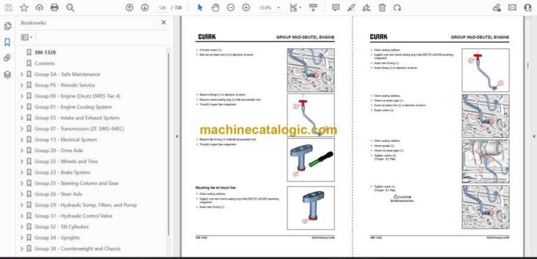
SM-1328
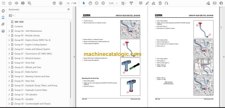
Contents
Group SA – Safe Maintenance
Section 1 – Safety
Section 2 – Lifting, Jacking, and Blocking the Truck
Section 3 – Towing
Group PS – Periodic Service
Section 1 – Maintenance Schedules
Section 2 – The Planned Maintenance Program
Group 00 – Engine (Deutz EMR5 Tier 4)
Section 1 – General
Section 2 – Servicing and Maintenance Work
Section 3 – Removing and Installing
Section 4 – Special Tools
Group 01 – Engine Cooling System
Section 1 – Specifications and Description
Section 2 – Troubleshooting
Section 3 – Testing and Maintenance
Section 4 – Radiator Removal and Replacement
Group 03 – Intake and Exhaust System
Section 1 – Specifications and Description
Section 2 – Troubleshooting
Section 3 – Intake System Service
Section 4 – Exhaust Systems
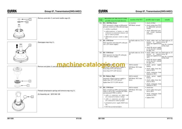
Group 07 – Transmission (ZF 3WG-94EC)
Section 1 – Layout (3WG-94EC)
Section 2 – Measuring Points and Connections
Section 3 – Disassembly
Section 4 – Reassembly
Section 5 – Removal and Installation
Section 6 – AEB Setting of T/M Controller Clutch & Inching Calibration
Section 7 – Troubleshooting
Group 13 – Electrical System
Section 1 – Cautions for Working on the Electrical System
Section 2 – Specifications and Features
Section 3 – Electrical Circuit Diagram & Electrical Parts Arrangement
Section 4 – Instrument Pod
Section 5 – Air Conditioning System (Option)
Group 20 – Drive Axle
Section 1 – System Operation
Section 2 – Differential Carrier Assembly
Section 3 – Drive Axle
Section 4 – Problem and Cause
Section 5 – Disassembly and Reassembly
Section 6 – Removal and Installation
Group 22 – Wheels and Tires
Section 1 – Specifications and Description
Section 2 – Pneumatic Wheels and Tires
Group 23 – Brake System
Section 1 – Brake / Inching System Specifications and Description
Section 2 – Troubleshooting
Section 3 – Brake / Inching Pedals and Linkages Adjustments
Section 4 – Brake System Bleeding
Section 5 – Brake Valve Service
Section 6 – Parking Brake Service
Group 25 – Steering Column and Gear
Section 1 – Specifications and Description
Section 2 – Steering System Troubleshooting
Section 3 – Steering Column and Component Removal and Replacement
Section 4 – Steering System Relief Pressure Check and Adjustment
Section 5 – Steering Gear Overhaul
Group 26 – Steer Axle
Section 1 – Specifications and Description
Section 2 – Wheel Bearing Maintenance and Adjustment
Section 3 – Removal and Replacement
Section 4 – Overhaul
Section 5 – Steer Cylinder Removal and Replacement
Section 6 – Steer Cylinder Overhaul
Group 29 – Hydraulic Sump, Filters, and Pump
Section 1 – Specifications and Description
Section 2 – Main Hydraulic Pump Troubleshooting
Section 3 – Main Hydraulic Pump Removal and Installation
Group 31 – Hydraulic Control Valve
Section 1 – Operation of Hydraulic Control Valve
Section 2 – Hydraulic Circuit
Section 3 – Disassembling Hydraulic Valve
Section 4 – Assembling Hydraulic Valve
Section 5 – Hydraulic System Pressure Checks and Adjustments
Section 6 – Hydraulic Control Valve Removal and Replacement
Section 7 – Testing Hydraulic Valve
Section 8 – EHL Valve Disassembly and Assembly
Group 32 – Tilt Cylinders
Section 1 – Specifications and Description
Section 2 – Checks and Adjustments
Section 3 – Removal and Replacement
Section 4 – Overhaul
Group 34 – Uprights
Section 1 – Specifications and Description
Section 2 – Troubleshooting
Section 3 – Upright Inspection
Section 4 – Carriage and Upright Roller Clearance Checks and Shim Adjustments
Section 5 – Cylinder Removal, Shimming, Overhaul, and Replacement
Section 6 – Upright Chain Inspection, Adjustment, and Replacement
Section 7 – Fork and Carriage Removal and Replacement
Section 8 – Upright Removal and Replacement
Group 38 – Counterweight and Chassis
Section 1 – Specifications and Description
Section 2 – Counterweight Removal and Replacement
Section 3 – Overhead Guard / Operator’s Cell Removal and Replacement
Section 4 – Floorboard, Cowls, and Seat Deck Removal and Replacement
Section 5 -Operator’ s Seat Removal and Replacement
Group 40 – Specifications
Section 1 – Nameplates and Decals
Section 2 – General Specifications
Section 3 – Hydraulic Fitting Tightening Procedure
