Format: PDF (Printable Document)
File Language: English
File Pages: 907
File Size: 14.03 MB (Speed Download Link)
Brand: John Deere
Model: 230LCR Hydraulic Excavator
Book No: TM 5-3805-280-24-1
Type of Document: Technical Manual
$ 40
The 230LCR is a tight-tail excavator that lives in tight urban cuts, roadside ditches, and around foundations where you’re always working close to obstacles. This technical manual is what we grab when a fault isn’t obvious and we need to trace it through the machine step by step. It helps you verify the basics before you start turning wrenches—whether you’re chasing a slow boom, an overheating hydraulic system, or an electrical issue that only shows up after a few hours of digging.
Applications & Use Cases
FAQ
Q: Can I use this manual on a tablet in the field?
A: Yes, it’s practical to keep it on a tablet or laptop so you can zoom diagrams, search quickly, and keep greasy hands off the paperwork.
Q: Is it worth printing sections of this manual?
A: Many techs print the pages they need for a specific job, mark them up during testing, then file or reprint fresh copies as needed.
Safety Note
Always lock out, support, and relieve hydraulic pressure exactly as directed in the manual before inspecting or loosening any components.
TABLE OF CONTENTS
TM 5-3805-280-24-1
Page
Chapter 1 Section 9000 General Information
01 Safety……………………………………………………………………………………………….1-1
Follow Safe Procedures………………………………………………………………….1-1
Prepare for Emergencies ………………………………………………………………..1-1
Handle Fluids Safely—Avoid Fires …………………………………………………1-1
Prevent Battery Explosions …………………………………………………………….1-2
Handle Chemical Products Safely……………………………………………………1-2
Prevent Acid Burns ……………………………………………………………………….1-3
Avoid High-Pressure Fluids ……………………………………………………………1-4
Warn Others of Service Work …………………………………………………………1-4
Park Machine Safely ……………………………………………………………………..1-5
Support Machine Properly………………………………………………………………1-5
Operate Only From Operator’s Seat…………………………………………………1-5
TM 5-3805-280-24-1
TABLE OF CONTENTS (Continued)
Page
ii
Stay Clear of Moving Parts …………………………………………………………….1-6
Avoid Power Lines………………………………………………………………………..1-6
Use Handholds and Steps ……………………………………………………………….1-6
Keep Riders Off Machine……………………………………………………………….1-7
Move and Operate Machine Safely ………………………………………………….1-7
Wear Protective Clothing ……………………………………………………………….1-7
Protect Against Flying Debris …………………………………………………………1-8
Protect Against Noise…………………………………………………………………….1-8
Illuminate Work Area Safely…………………………………………………………..1-8
Service Machines Safely ………………………………………………………………..1-8
Remove Paint Before Welding or Heating………………………………………..1-9
Avoid Heating Near Pressurized Fluid Lines …………………………………….1-9
Beware of Exhaust Fumes………………………………………………………………1-10
Use Proper Lifting Equipment…………………………………………………………1-10
Service Cooling System Safely ……………………………………………………….1-10
Dispose of Waste Properly……………………………………………………………..1-11
Work in a Clean Area…………………………………………………………………….1-11
Use Tools Properly………………………………………………………………………..1-12
Replace Safety Signs ……………………………………………………………………..1-12
Live With Safety …………………………………………………………………………..1-12
Battery Terminals, Lifting Equipment, Dry Cleaning, Solvent
and Compressed Air ……………………………………………………………………1-13
Compressor Equipment Hazards ……………………………………………………..1-14
Rock Drill Precautions …………………………………………………………………..1-16
02 General Specifications ………………………………………………………………………..1-19
03 Torque Values……………………………………………………………………………………1-20
Unified Inch Bolt and Cap Screw Torque Values ………………………………1-20
Metric Bolt and Cap Screw Torque Values……………………………………….1-21
Additional Metric Cap Screw Torque Values ……………………………………1-22
Check Oil Lines and Fittings…………………………………………………………..1-23
Service Recommendations for O-Ring Boss Fittings………………………….1-24
Service Recommendations for Flat Face O-Ring Seal Fittings …………….1-26
Service Recommendations for 37° Flare and
30° Cone Seat Connectors …………………………………………………………..1-27
Service Recommendations for Flared Connections—
Straight or Tapered Threads ………………………………………………………..1-28
Service Recommendations for Inch Series Four Bolt Flange Fittings……1-29
Service Recommendations for Metric Series Four Bolt Flange Fitting….1-31
04 Fuels and Lubricants…………………………………………………………………………..1-32
Diesel Fuel …………………………………………………………………………………..1-32
Lubricity of Diesel Fuels………………………………………………………………..1-32
Low Sulfur Diesel Fuel Conditioner ………………………………………………..1-33
Diesel Fuel Storage ……………………………………………………………………….1-33
Fuel Tank …………………………………………………………………………………….1-34
Do Not Use Galvanized Containers …………………………………………………1-34
Diesel Engine and Pump Gearbox Oils …………………………………………….1-35
Hydraulic Oil………………………………………………………………………………..1-36
Swing Gearbox and Propel Gearbox Oils………………………………………….1-37
Track Roller, Front Idler, and Carrier Roller Oil ……………………………….1-37
Track Adjuster, Working Tool Pivot, Swing Bearing, and
Swing Bearing Gear Grease…………………………………………………………1-38
Oil Filters …………………………………………………………………………………….1-38
Rock Drill Lubricants Specifications ……………………………………………….1-39
Lubricant Storage ………………………………………………………………………….1-41
Alternative and Synthetic Lubricants ……………………………………………….1-41
Mixing of Lubricants……………………………………………………………………..1-42
Air Compressor Lubrication……………………………………………………………1-43
Chapter 2 Section 9005 Operational Checkout Procedure
10 Operational Checkout Procedure………………………………………………………….2-1
Operational Checkout…………………………………………………………………….2-1
Operator Station Checks—Key Switch On, Engine Off ……………………..2-2
Operator Station Checks—Engine On………………………………………………2-5
Hydraulic System Checks ………………………………………………………………2-11
Undercarriage Checks ……………………………………………………………………2-19
Accessories Checks ……………………………………………………………………….2-21
Seat, Doors, Windows, Latches, and Locks Checks……………………………2-23
Engine Cooling System Checks ………………………………………………………2-29
Air Intake System Checks ………………………………………………………………2-33
Fuel System Checks ………………………………………………………………………2-36
Visual Inspection…………………………………………………………………………..2-38
Chapter 3 Section 9010 Engine
05 Theory of Operation …………………………………………………………………………..3-1
Engine—Sectional View………………………………………………………………..3-1
Fan Drive……………………………………………………………………………………..3-2
Engine Speed Control
System Operation……………………………………………………………………….3-3
Engine RPM Dial……………………………………………………………………….3-5
E (Economy) Mode…………………………………………………………………….3-7
HP (High Power) Mode ………………………………………………………………3-8
Auto-Idle Mode …………………………………………………………………………3-10
Engine Speed Learning……………………………………………………………….3-11
10 System Operational Checks…………………………………………………………………3-13
Engine Operational Checks …………………………………………………………….3-13
Cooling System Checks………………………………………………………………….3-13
Air Intake System Checks ………………………………………………………………3-18
Lubrication System Checks…………………………………………………………….3-21
Fuel System Checks ………………………………………………………………………3-23
Engine Speed and Performance Checks ……………………………………………3-25
15 Diagnostic Information……………………………………………………………………….3-28
Diagnose Engine Malfunctions ……………………………………………………….3-28
20 Adjustments ………………………………………………………………………………………3-40
JT05801 Clamp-On Electronic Tachometer Installation……………………..3-40
Fuel Shut-Off Solenoid Linkage, Check and Adjust …………………………..3-41
Engine Speed Check………………………………………………………………………3-44
Injection Pump Fast and Slow Idle Stops………………………………………….3-45
Engine Control Motor and Sensor……………………………………………………3-48
Engine Speed Learning Procedure …………………………………………………..3-49
Cooling System Fill and Deaeration…………………………………………………3-51
25 Tests…………………………………………………………………………………………………3-52
Fuel Line Leakage…………………………………………………………………………3-52
Air Filter Restriction Indicator Switch ……………………………………………..3-53
Air Intake System Leakage …………………………………………………………….3-54
Radiator Air Flow………………………………………………………………………….3-55
Engine Power Test Using Turbocharger Boost Pressure……………………..3-58
Torsional Dampener, Inspect ………………………………………………………….3-62
TM 5-3805-280-24-1
TABLE OF CONTENTS (Continued)
Page
iv
Chapter 4 Section 9015 Electrical System
05 System Information ……………………………………………………………………………4-1
Visually Inspect Electrical System…………………………………………………..4-1
Circuit Malfunctions
Circuit Malfunctions…………………………………………………………………..4-2
Definition………………………………………………………………………………….4-3
Location ……………………………………………………………………………………4-8
Troubleshooting…………………………………………………………………………4-9
Circuit Shorted to Power and Circuit Shorted to Itself………………………..4-11
Using Test Equipment
Multimeter ………………………………………………………………………………..4-14
Seven Step Electrical Test Procedure ……………………………………………4-15
System Functional Schematic Information………………………………………..4-16
Reading a System Functional Schematic Diagram……………………………..4-17
Reading a Harness Component Location Diagram …………………………….4-19
Electrical Schematic Symbols …………………………………………………………4-23
10 System Diagrams……………………………………………………………………………….4-26
Fuse Specifications………………………………………………………………………..4-26
Fuse (Blade-Type) Color Codes………………………………………………………4-27
Component Identification Table………………………………………………………4-27
Functional Schematic and Component Location Legend…………………….4-29
System Functional Schematic Section Legend…………………………………..4-33
System Functional Schematic (SE1—SE3)……………………………………….4-34
System Functional Schematic (SE4—SE6)……………………………………….4-35
System Functional Schematic (SE7—SE9)……………………………………….4-36
System Functional Schematic (SE10—SE12)……………………………………4-37
System Functional Schematic (SE13—SE15)……………………………………4-38
System Functional Schematic (SE16—SE18)……………………………………4-39
System Functional Schematic (SE19) ………………………………………………4-40
Engine and Frame Harness (W1)
Component Location ………………………………………………………………….4-41
Connectors, Wire and Pin Location ………………………………………………4-45
Air Compressor and Rock Drill Harness (W10) Component Location….4-49
Cab Harness (W2)
Component Location ………………………………………………………………….4-50
Component Location—Detail A (Harness Mating Connectors) ………..4-51
Component Location—Detail B (Fuse Block)………………………………..4-53
Connectors, Wire and Pin Location ………………………………………………4-54
Monitor and Relay Harness (W3)
Component Location ………………………………………………………………….4-60
Component Location—Detail A (Monitor Controller Connectors) ……4-61
Component Location—Detail B (Monitor Controller Indicators) ……..4-62
Connectors, Wire and Pin Location ………………………………………………4-63
Air Conditioner Harness (W9)
Component Location—See Group 9031-15 …………………………………..4-65
Connectors, Wire and Pin Location—See Group 9031-15……………….4-65
15 Sub-System Diagnostics ……………………………………………………………………..4-66
Power Circuit
Operational Information ……………………………………………………………..4-66
Theory of Operation …………………………………………………………………..4-67
Schematic………………………………………………………………………………….4-68
Power Circuit Diagnostic Procedures……………………………………………….4-69
Charging Circuit
Operational Information ……………………………………………………………..4-73
Theory of Operation …………………………………………………………………..4-73
Schematic………………………………………………………………………………….4-74
Alternator Theory of Operation……………………………………………………….4-75
Charging Circuit Diagnostic Procedures …………………………………………..4-76
Starting and Fuel Shutoff Circuit
Operational Information ……………………………………………………………..4-80
Theory of Operation …………………………………………………………………..4-80
Schematic………………………………………………………………………………….4-81
Starting Circuit Diagnostic Procedures …………………………………………….4-82
Windshield Wiper and Washer Circuit
Operational Information ……………………………………………………………..4-88
Theory of Operation …………………………………………………………………..4-89
Schematic………………………………………………………………………………….4-91
Windshield Wiper and Washer Circuit Diagnostic Procedures…………….4-92
Work and Drive Light Circuit
Operational Information ……………………………………………………………..4-97
Theory of Operation …………………………………………………………………..4-97
Schematic………………………………………………………………………………….4-98
Work and Drive Light Circuit Diagnostic Procedures ………………………..4-99
Accessory Circuits
Operational Information ……………………………………………………………..4-102
Theory of Operation …………………………………………………………………..4-102
Schematic………………………………………………………………………………….4-103
Accessory Circuits Diagnostic Procedures………………………………………..4-104
Quick Hitch Circuit
Operational Information ……………………………………………………………..4-106
Theory of Operation …………………………………………………………………..4-106
Schematic………………………………………………………………………………….4-107
Quick Hitch Circuit Diagnostic Procedures ………………………………………4-107
Heater Circuit (Machines Without Air Conditioner)…………………………..4-108
Heater Circuit (Machines With Air Conditioner)……………………………….4-109
Monitor Controller and Display Circuit
Specifications…………………………………………………………………………….4-110
Operational Information ……………………………………………………………..4-111
Theory of Operation …………………………………………………………………..4-112
Schematic………………………………………………………………………………….4-115
Monitor Controller and Display Circuit Diagnostic Procedures …………..4-116
Engine and Pump Controller Circuit
Operational Information ……………………………………………………………..4-133
Theory of Operation …………………………………………………………………..4-134
Schematic………………………………………………………………………………….4-136
Engine and Pump Controller Circuit Diagnostic Procedures ……………….4-137
Travel Alarm Circuit
Operational Information ……………………………………………………………..4-160
Theory of Operation …………………………………………………………………..4-160
Schematic………………………………………………………………………………….4-161
Travel Alarm Circuit Diagnostic Procedures …………………………………….4-162
Overload Alarm Circuit
Operational Information ……………………………………………………………..4-165
Theory of Operation …………………………………………………………………..4-165
Schematic………………………………………………………………………………….4-166
Overload Alarm Circuit Diagnostic Procedures…………………………………4-166
20 References ………………………………………………………………………………………..4-169
Battery
Operation ………………………………………………………………………………….4-169
Specifications…………………………………………………………………………….4-170
TM 5-3805-280-24-1
TABLE OF CONTENTS (Continued)
Page
vi
Diagnose Malfunctions ……………………………………………………………….4-171
Check Electrolyte Level and Terminals…………………………………………4-172
Batteries
Procedure for Testing …………………………………………………………………4-174
Using Booster Batteries—24 Volt System……………………………………..4-175
Replacing ………………………………………………………………………………….4-176
Adding 12 or 24 Volt Accessories ………………………………………………..4-177
Travel Alarm, Changing Volume …………………………………………………….4-178
Test Harness
Proportional Solenoid …………………………………………………………………4-179
Pump Control…………………………………………………………………………….4-179
Pump Pressure Sensor…………………………………………………………………4-179
Chapter 5 Section 9020 Power Train
05 Theory of Operation …………………………………………………………………………..5-1
Track Adjuster………………………………………………………………………………5-1
Propel Gearbox……………………………………………………………………………..5-2
15 Diagnostic Information……………………………………………………………………….5-4
Diagnose Undercarriage Components Malfunctions…………………………..5-4
Track Chain
Measure Bushing Wear……………………………………………………………….5-6
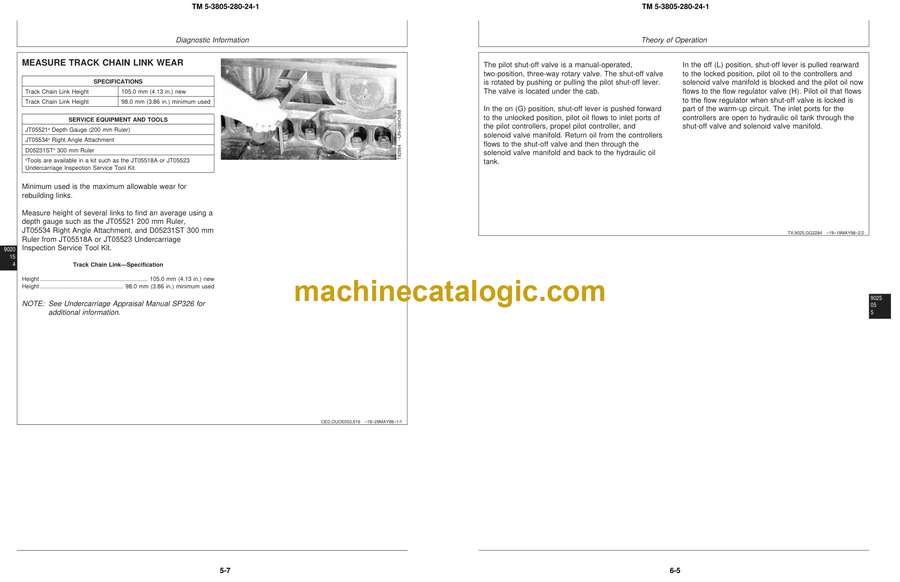
Measure Link Wear ……………………………………………………………………5-7
Measure Pitch ……………………………………………………………………………5-8
Track Shoe Grouser
Measure Wear (SN —599999) …………………………………………………….5-9
Measure Wear (SN 600000—) …………………………………………………….5-10
Track Roller, Measure Wear …………………………………………………………..5-11
Track Carrier Roller, Measure Wear………………………………………………..5-12
Front Idler, Measure Wear ……………………………………………………………..5-13
Swing Bearing, Measure Wear………………………………………………………..5-14
20 Adjustments ………………………………………………………………………………………5-16
Track Sag …………………………………………………………………………………….5-16
Chapter 6 Section 9025 Hydraulic System
05 Theory of Operation …………………………………………………………………………..6-1
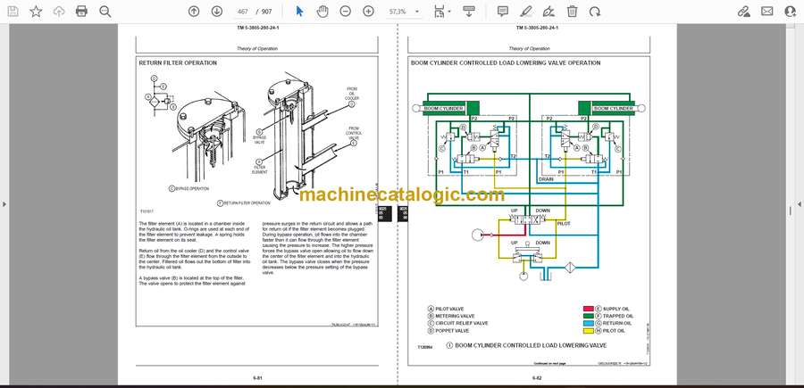
Hydraulic System Diagram…………………………………………………………….6-1
Pilot Pump Operation …………………………………………………………………….6-2
Pilot Pressure Regulating Valve and Filter Operation…………………………6-3
Pilot Shut-Off Valve Operation……………………………………………………….6-4
Pilot Controller
Neutral ……………………………………………………………………………………..6-6
Metering and Full Stroke …………………………………………………………….6-7
Propel Pilot Controller …………………………………………………………………..6-8
Pilot Controller Operation of Control Valve ……………………………………..6-10
Flow Regulator Valve ……………………………………………………………………6-11
Hydraulic Pump and Drive Gearbox ………………………………………………..6-13
Hydraulic Pump Operation……………………………………………………………..6-15
Hydraulic Pump Regulator
Component Operation…………………………………………………………………6-17
Operation ………………………………………………………………………………….6-19
Increasing, Maximum, and Decreasing …………………………………………6-21
Summation and Speed Sensing…………………………………………………….6-23
Proportional Solenoid Valve
Manifold Operation ……………………………………………………………………6-25


