$ 0
0
$ 0
0

John Deere 160GLC, 180GLC Excavator Operators Manual (OMT306200)

Format: PDF (Printable Document)

File Language: English
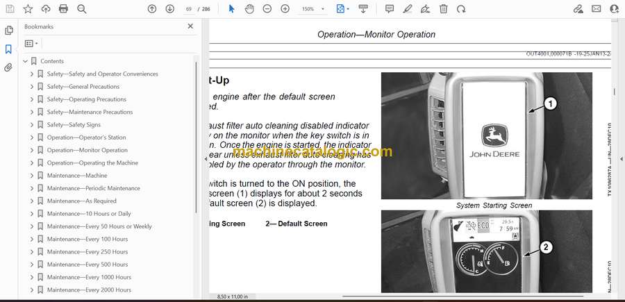
File Pages: 286

File Size: 6.66 MB (Speed Download Link)

Brand: John Deere

Model: 160GLC, 180GLC Excavator

Book No: OMT306200

Type of Document: Operators Manual

Categories: ,

$ 40

Share:

John Deere 160GLC, 180GLC Excavator Operators Manual (OMT306200)

John Deere 160GLC, 180GLC Excavator Operators Manual (OMT306200)

📘 Show Index

John Deere 160GLC, 180GLC Excavator Index:

  • Contents
    • Safety—Safety and Operator Conveniences
      • Safety and Operator Convenience Features
    • Safety—General Precautions
      • Recognize Safety Information
      • Follow Safety Instructions
      • Operate Only If Qualified
      • Wear Protective Equipment
      • Avoid Unauthorized Machine Modifications
      • Control Pattern Selector—If Equipped
      • Add Cab Guarding for Special Uses
      • Inspect Machine
      • Stay Clear of Moving Parts
      • Avoid High-Pressure Fluids
      • Avoid High-Pressure Oils
      • Work In Ventilated Area
      • Avoid Static Electricity Risk When Refueling
      • Prevent Fires
      • Prevent Battery Explosions
      • Handle Chemical Products Safely
      • Dispose of Waste Properly
      • Exhaust Filter Ash Handling and Disposal
      • Prepare for Emergencies
      • Clean Debris from Machine
    • Safety—Operating Precautions
      • Use Steps and Handholds Correctly
      • Start Only From Operator’s Seat
      • Use and Maintain Seat Belt
      • Prevent Unintended Machine Movement
      • Avoid Work Site Hazards
      • Keep Riders Off Machine
      • Avoid Backover Accidents
      • Inspect and Maintain ROPS
      • Avoid Machine Tip Over
      • Use Special Care When Lifting Objects
      • Use Special Care When Operating
      • Travel Safely
      • Prevent Acid Burns
      • Add and Operate Attachments Safely
    • Safety—Maintenance Precautions
      • Park and Prepare for Service Safely
      • Service Cooling System Safely
      • Remove Paint Before Welding or Heating
      • Make Welding Repairs Safely
      • Drive Metal Pins Safely
      • Clean Exhaust Filter Safely
    • Safety—Safety Signs
      • Safety Signs
      • Hydraulic Coupler Safety Signs—If Equipped
    • Operation—Operator’s Station
      • Pedals, Levers, and Panels
      • Switch Panel
      • Switch Panel Functions
      • Rear Left Panel
      • Horn
      • Power Dig Button
      • Pilot Shutoff Lever
      • Left Console
      • Travel Alarm and Travel Alarm Cancel Switch
      • Seat Heater Switch—If Equipped
      • Reversing Fan Switch—If Equipped
      • Right Console
      • Exhaust Filter Parked Cleaning Switch
      • Right Enable Switch
      • Service ADVISOR™ Remote (SAR) Switch
      • Cab Heater and Air Conditioner
      • Selecting Display Between Celsius and Fahrenheit
      • Operating the AM/FM Radio
      • Fire Extinguisher Mounting Location
      • Secondary Exit Tool
      • Cab Dome Light Switch
      • Opening Upper Front (Secondary Exit) Window
      • Removing and Storing the Lower Front Window
      • Opening Cab Door Window
      • Opening and Closing the Polycarbonate Type Roof Exit Cover
      • Adjusting the Mechanical Suspension Seat
      • Adjusting the Air Suspension Seat—If Equipped
      • Adjusting Pilot Control Lever Console Height
    • Operation—Monitor Operation
      • Monitor
      • Monitor Functions
      • Monitor Start-Up
      • Main Menu
      • Main Menu—Alarm List
      • Main Menu—Air Conditioner
      • Main Menu—Radio
      • Main Menu—Work Mode
      • Main Menu—Setting Menu
      • Main Menu—Setting Menu—Date and Time
      • Main Menu—Setting Menu—Attachment Name Input
      • Main Menu—Setting Menu—Auto Shutdown
      • Main Menu—Setting Menu—Auto Exhaust Filter Cleaning
      • Main Menu—Setting Menu—Sub Meter Selection
      • Main Menu—Setting Menu—Rear View Camera Monitor
      • Main Menu—Setting Menu—Display Item Selection
      • Main Menu—Setting Menu—Brightness Adjustment
      • Main Menu—Setting Menu—Language
      • Main Menu—Setting Menu—Unit Selection
      • Main Menu—Setting Menu—Main Menu Sequence Change
      • Main Menu—Information Menu
      • Main Menu—Information Menu—Operation
      • Main Menu—Information Menu—Maintenance
      • Main Menu—Information Menu—Troubleshooting
      • Main Menu—Information Menu—Monitoring
    • Operation—Operating the Machine
      • Before Starting Work
      • Operator’s Daily Machine Check Before Starting
      • Engine Break-In Period
      • Starting Engine
      • Cold Weather Start Aid
      • Cold Weather Warmup
      • Travel Pedals and Levers
      • Exhaust Filter
      • Exhaust Filter Parked Cleaning
      • Service ADVISOR™ Remote (SAR) Software Delivery Process
      • Service ADVISOR™ Remote (SAR) Operation
      • Locking the Hydraulic Coupler to the Attachment—If Equipped
      • Unlocking the Hydraulic Coupler From the Attachment—If Equipped
      • Control Lever Pattern Operation
      • Mechanical Control Lever Pattern Selector—If Equipped
      • Control Lever Pattern Conversion
      • Operating in Water and Mud
      • Driving Up a Steep or Slippery Slope
      • Lifting
      • Lower Boom With Engine Stopped
      • Parking the Machine
      • Loading and Unloading for Transport
      • Towing Machine
      • Lifting the Machine
    • Maintenance—Machine
      • Diesel Fuel
      • Diesel Fuel Specifications
      • Lubricity of Diesel Fuel
      • Handling and Storing Diesel Fuel
      • Biodiesel Fuel
      • Testing Diesel Fuel
      • Fuel Filters
      • Minimizing the Effect of Cold Weather on Diesel Engines
      • Alternative and Synthetic Lubricants
      • Mixing of Lubricants
      • Lubricant Storage
      • John Deere Break-In Plus™ Engine Oil
      • Diesel Engine Oil—Interim Tier 4 and Stage III B Engines
      • Engine Oil and Filter Service Intervals — Interim Tier 4, Final Tier 4, Stage IIIB, and Stage IV Engines
      • Oil Filters
      • Hydraulic Oil
      • Swing Gear Case and Travel Gear Case Oils
      • Pump Drive Gear Case Oil
      • Track Adjuster, Working Tool Pivot, Swing Bearing, and Swing Bearing Gear Grease
      • Diesel Engine Coolant (engine with wet sleeve cylinder liners)
      • Drain Intervals for Diesel Engine Coolant
      • John Deere COOL-GARD™ II Coolant Extender
      • Supplemental Coolant Additives
      • Operating in Warm Temperature Climates
      • Additional Information About Diesel Engine Coolants and John Deere COOL-GARD™ II Coolant Extender
      • Testing Diesel Engine Coolant
      • Disposing of Coolant
    • Maintenance—Periodic Maintenance
      • Service Machine at Specified Intervals
      • Check the Hour Meter Regularly
      • Prepare Machine for Maintenance
      • Open Access Doors for Service
      • Open Engine Cover for Service
      • Fuel Tank
      • Hydraulic Breaker and Crusher Attachments
      • Fluid Analysis Program Test Kits and 3-Way Coolant Test Kit
      • Service Intervals
      • Required Parts
    • Maintenance—As Required
      • Remove and Clean Fuel Tank Inlet Screen
      • Check Windshield Washer Fluid Level
      • Check and Clean Air Cleaner Dust Unloader Valve
      • Check and Adjust Track Sag
      • Clean Rear Camera Lens—If Equipped
      • Check Coolant
      • Service Exhaust Filter
    • Maintenance—10 Hours or Daily
      • Check Engine Oil Level
      • Check Engine Coolant Level
      • Check Hydraulic Tank Oil Level
      • Lubricate Hydraulic Coupler—If Equipped
    • Maintenance—Every 50 Hours or Weekly
      • Drain Water and Sediment from Fuel Tank Sump
      • Drain Primary Fuel Filter and Water Separator
      • Drain Final Fuel Filter
      • Drain Auxiliary Fuel Filter and Water Separator—If Equipped
    • Maintenance—Every 100 Hours
      • Lubricate Working Tool Pivots
      • Inspect and Re-Torque Track Hardware
    • Maintenance—Every 250 Hours
      • Check Swing Gear Case Oil Level
      • Drain Water and Sediment from Hydraulic Tank
      • Check Pump Drive Gear Case Oil Level
      • Check Battery Electrolyte Level and Terminals
      • Check Travel Gear Case Oil Level
      • Take Engine Oil Sample
    • Maintenance—Every 500 Hours
      • Lubricate Front End Pin Joints
      • Lubricate Swing Bearing
      • Lubricate Swing Bearing Gear
      • Replace Primary Fuel Filter and Water Separator
      • Replace Final Fuel Filter
      • Replace Auxiliary Fuel Filter and Water Separator—If Equipped
      • Check Air Intake Hoses
      • Drain and Refill Engine Oil and Replace Filter
      • Clean Cab Fresh Air and Cab Recirculating Air Filters
      • Take Fluid Samples
    • Maintenance—Every 1000 Hours
      • Drain and Refill Swing Gear Case Oil
      • Replace Hydraulic Tank Oil Filter
      • Replace Pilot Oil Filter
      • Drain and Refill Pump Drive Gear Case Oil
      • Remove and Clean Open Crankcase Ventilation (OCV) Hose
      • Inspect Serpentine Belt
      • Replace Air Cleaner Elements
      • Replace Air Cleaner Dust Unloader Valve
      • Check Coolant
    • Maintenance—Every 2000 Hours
      • Check and Adjust Engine Valve Lash
      • Drain and Refill Travel Gear Case Oil
      • Replace Open Crankcase Ventilation (OCV) Filter
    • Maintenance—Every 5000 Hours
      • Drain and Refill Hydraulic Tank Oil
      • Replace Hydraulic Tank Vent Cap Filter
    • Maintenance—Every 6000 Hours
      • Drain Cooling System
      • Cooling System Fill and Deaeration Procedure
    • Miscellaneous—Machine
      • Bleed Fuel System
      • Clean Radiator, Oil Cooler, Charge Air Cooler, and Fuel Cooler
      • Do Not Service or Adjust Injection Nozzles or High-Pressure Fuel Pump
      • Do Not Service Control Valves, Cylinders, Pumps, or Motors
      • Precautions for Alternator and Regulator
      • Handling, Checking, and Servicing Batteries Carefully
      • Using Battery Charger
      • Using Booster Batteries—24-Volt System
      • Replacing Batteries
      • Fluid Sampling Test Ports—If Equipped
      • Welding On Machine
      • Clean the Machine Regularly
      • Adding 12—Volt Accessories
      • JDLink™ Machine Monitoring System (MMS)—If Equipped
      • Replacing Fuses
      • Replacing Bucket Teeth
      • Replacing Bucket Tooth Tip—Heavy-Duty Bucket
      • Replacing Bucket Teeth—TK Series
      • Removing the Bucket
      • Track Sag General Information
      • Check Track Shoe Hardware
      • Hardware Torque Specifications
      • Unified Inch Bolt and Screw Torque Values
      • Metric Bolt and Screw Torque Values
    • Miscellaneous—Operational Checkout
      • Operational Checkout
    • Miscellaneous—Troubleshooting
      • Troubleshooting Procedure
      • Engine
      • Hydraulic System
      • Electrical System
    • Miscellaneous—Storage
      • Prepare Machine for Storage
      • Monthly Storage Procedure
    • Miscellaneous—Machine Numbers
      • Record Product Identification Number (PIN)
      • Record Engine Serial Number
      • Record Travel Motor Serial Numbers
      • Record Swing Motor Serial Number
      • Record Hydraulic Coupler Serial Number—If Equipped
      • Hydraulic Pump Serial Number
      • Keep Proof of Ownership
      • Keep Machines Secure
    • Miscellaneous—Specifications
      • 160GLC Engine Specifications
      • 180GLC Engine Specifications
      • 160GLC and 180GLC Drain and Refill Capacities
      • 160GLC Machine Specifications
      • 180GLC Machine Specifications
      • 160GLC Working Ranges
      • 180GLC Working Ranges
      • 160GLC Lift Capacity—Arm: 2.60 m (8 ft. 6 in.); Bucket: 528 kg (1164 lb.); Shoe: 600 mm (24 in.)
      • 160GLC Lift Capacity—Arm: 2.60 m (8 ft. 6 in.); Bucket: 528 kg (1164 lb.); Shoe: 700 mm (28 in.)
      • 160GLC Lift Capacity—Arm: 3.10 m (10 ft. 2 in.); Bucket: 528 kg (1164 lb.); Shoe: 600 mm (24 in.)
      • 160GLC Lift Capacity—Arm: 3.10 m (10 ft. 2 in.); Bucket: 528 kg (1164 lb.); Shoe: 700 mm (28 in.)
      • 180GLC Lift Capacity—Arm: 2.71 m (8 ft. 10 in.); Bucket: 600 kg (1323 lb.); Shoe: 600 mm (24 in.)
      • 180GLC Lift Capacity—Arm: 2.71 m (8 ft. 10 in.); Bucket: 600 kg (1323 lb.); Shoe: 700 mm (28 in.)
      • 180GLC Lift Capacity—Arm: 2.71 m (8 ft. 10 in.); Bucket: 600 kg (1323 lb.); Shoe: 800 mm (32 in.)
      • 180GLC Lift Capacity—Arm: 3.21 m (10 ft. 6 in.); Bucket: 600 kg (1323 lb.); Shoe: 600 mm (24 in.)
      • 180GLC Lift Capacity—Arm: 3.21 m (10 ft. 6 in.); Bucket: 600 kg (1323 lb.); Shoe: 700 mm (28 in.)
      • 180GLC Lift Capacity—Arm: 3.21 m (10 ft. 6 in.); Bucket: 600 kg (1323 lb.); Shoe: 800 mm (32 in.)
  • Page Number
    • Section 1-1
    • Section 1-2
    • Section 1-3
    • Section 1-4
    • Section 1-5
    • Section 2-1
    • Section 2-2
    • Section 2-3
    • Section 3-1
    • Section 3-2
    • Section 3-3
    • Section 3-4
    • Section 3-5
    • Section 3-6
    • Section 3-7
    • Section 3-8
    • Section 3-9
    • Section 3-10
    • Section 3-11
    • Section 3-12
    • Section 4-1
    • Section 4-2
    • Section 4-3
    • Section 4-4
    • Section 4-5
    • Section 4-6

John Deere

Latest Product

🎄 New Year Deal: 12% OFF on all products — Use code MCAT12
0
    0
    Your Cart
    Your cart is emptyReturn to Shop