Format: PDF (Printable Document)
File Language: English
File Pages: 1154
File Size: 94.42 MB (Speed Download Link)
Brand: Link Belt
Model: 130X2 Excavator
Type of Document: Service Text Manual
$ 40
2 Engine
2-2 Procedures for Replacing Consumable Parts
1 Engine Oil…………………………………………………………………………………………… 1
2 Removal and Installation of Engine Oil Element ………………………………………. 3
3 Fuel Filter …………………………………………………………………………………………… 4
4 Charge Fuel Pump Filter ………………………………………………………………………. 8
5 Removal and Installation of Fan Belt ……………………………………………………… 10
6 Removal and Installation of Air Conditioner Belt ………………………………………. 12
2-3 Assembly and Disassembly
1 Removal and Installation of Engine Hood ……………………………………………….. 13
2 Removal and Installation of Engine Assembly …………………………………………. 15
3 Removal and Installation of Starter ………………………………………………………… 26
4 Removal and Installation of Alternator ……………………………………………………. 28
5 Removal and Installation of Common Rails …………………………………………….. 30
6 Removal and Installation of Supply Pump ………………………………………………. 33
7 Removal and Installation of Injector ……………………………………………………….. 39
8 Removal and Installation of Turbo …………………………………………………………. 43
9 Removal and Installation of Muffler………………………………………………………… 46
10 Removal and Installation of EGR Cooler ………………………………………………… 48
11 Removal and Installation of Engine Sensors …………………………………………… 51
12 Removal and Installation of Engine Inter Cooler ………………………………………. 52
13 Removal and Installation of Fuel Cooler …………………………………………………. 54
3 Air Conditioner
3-6 Assembly and Disassembly
1 Removal and Installation of Compressor ………………………………………………… 55
2 Removal and Installation of Condenser ………………………………………………….. 57
3 Removal and Installation of Receiver Dryer…………………………………………….. 59
4 Maintenance
4-9 Electric Equipment Checking Procedure
1 Voltage Measurement Procedure ………………………………………………………….. 61
5 Assembly and Disassembly
5-1 Lower Mechanism: Track Shoe
1 Removal and Installation of Shoe Assembly……………………………………………..63
2 Removal and Installation of Shoe Plates ………………………………………………….65
5-2 Lower Mechanism: Travel Drive Unit
1 Removal and Installation of Travel Motor Assembly…………………………………..66
2 Assembly and Disassembly of Travel Motor……………………………………………..71
3 Travel Motor Operator’s Manual ……………………………………………………………..169
5-3 Lower Mechanism: Take-up Roller
1 Take-up Roller Disassembly and Assembly ……………………………………………..207
5-4 Lower Mechanism: Upper Roller
1 Removal and Installation of Upper Roller …………………………………………………216
2 Assembly and Disassembly of Carrier Roller…………………………………………….218
5-5 Lower Mechanism: Lower Roller
1 Removal and Installation of Lower Roller …………………………………………………226
2 Assembly and Disassembly of Track Roller………………………………………………228
5-7 Swing Body: Swing Driving Unit
1 Removal and Installation of Swing Motor Assembly…………………………………..237
2 210 X2 Assembly and Disassembly of Swing Unit…………………………………….241
3 210 X2 Assembly and Disassembly of Swing Motor………………………………….256
4 240 X2 Assembly and Disassembly of Swing Motor………………………………….283
5 210 X2 Assembly and Disassembly of Swing Reduction Gear……………………312
6 240 X2 Assembly and Disassembly of Swing Reduction Gear……………………325
5-9 Swing Body: Center Joint
1 Removal and Installation of Center Joint ………………………………………………….343
5-10 Upper Swing Body: Counterweight
1 Removal and Installation of Counterweight ………………………………………………347
Contents
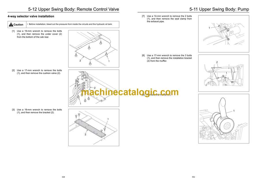
5-11 Upper Swing Body: Pump
1 Removal and Installation of Pump …………………………………………………………. 350
2 Assembly and Disassembly Procedures of Pump Main Unit ……………………… 355
3 Explanation of Regulator Operation ……………………………………………………….. 368
4 Regulator Disassembly and Assembly Procedures ………………………………….. 384
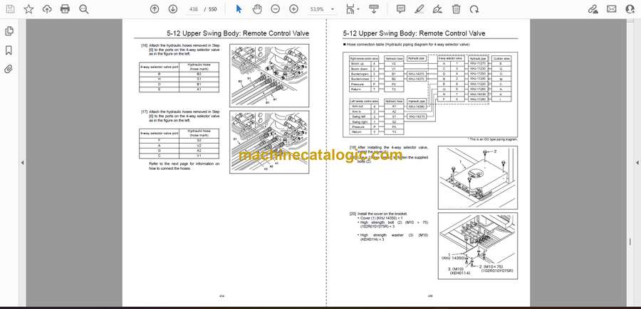
5-12 Upper Swing Body: Remote Control Valve
1 Explanation of Pilot Valve Operation………………………………………………………. 396
2 Removal and Installation of Joystick Remote Control Valve Assembly ……….. 418
3 Removal and Installation of Travel Remote Control Valve Assembly ………….. 423
4 4-Way Selector Valve Installation Procedure…………………………………………… 427
5-13 Upper Swing Body: Control Valve
1 Removal and Installation of Control Valve Assembly………………………………… 439
5-14 Upper Swing Body: Solenoid Valve
1 Removal and Installation of 5-Stack Solenoid Valve…………………………………. 447
2 Removal and Installation of Cushion Valve……………………………………………… 450
3 Assembly and Disassembly of Cushion Valve …………………………………………. 453
5-15 Upper Swing Body: Radiator and Oil Cooler
1 Removal and Installation of Radiator ……………………………………………………… 462
2 Removal and Installation of Oil Cooler……………………………………………………. 470
5-16 Upper Swing Body: Tank
1 Removal and Installation of Hydraulic Oil Tank………………………………………… 474
2 Removal and Installation of Fuel Tank……………………………………………………. 481
5-17 Structure: Attachment
1 Removal and Installation of Bucket………………………………………………………… 486
2 Removal and Installation of Bucket Link …………………………………………………. 488
3 Installation of Bucket Cylinder……………………………………………………………….. 491
4 Removal and Installation of Arm ……………………………………………………………. 494
5 Removal and Installation of Arm Cylinder ……………………………………………….. 496
6 Removal and Installation of Boom …………………………………………………………. 500
7 Removal and Installation of Boom Cylinder …………………………………………….. 505
8 Removal and Installation of Arm HBCV ………………………………………………….. 509
9 Removal and Installation of Boom HBCV ……………………………………………….. 511
5-18 Light
1 Removal and Installation of Boom Light …………………………………………………..514
2 Removal and Installation of Tool Box Light……………………………………………….515
5-20 Procedures for Removal and Installation of Cab Inner and Outer Parts
1 Removal and Installation of Cab Assembly ………………………………………………516
2 Removal and Installation of Operator’s Seat …………………………………………….523
3 Removal and Installation of Wiper …………………………………………………………..525
4-1Removal and Installation of Wiper Controller…………………………………………….526
4-2Removal and Installation of Wiper Motor ………………………………………………….529
5 Removal and Installation of Monitor…………………………………………………………532
6 Removal and Installation of Cab Front Glass ……………………………………………533
7 Adjustment Procedure of Window Lock……………………………………………………535
5-21 Hydraulic Equipment
1 Accumulator…………………………………………………………………………………………537
2 Suction Filter ………………………………………………………………………………………..538
3 Return Filter …………………………………………………………………………………………540
4 Pilot Filter …………………………………………………………………………………………….542
5-23 Others
1 Removal and Installation of Side Door……………………………………………………..543
2 Draining Oil from Hydraulic Oil Tank………………………………………………………..544


