Link Belt 80X3 Excavator Service Manual
The Link Belt 80X3 is a mid-size excavator that spends its life in dirt—trenching, loading trucks, working around utilities and tight jobsites. This service manual is what I’d keep open when I’m actually tearing into the machine or chasing an intermittent fault. If, for example, the boom drifts down under load, I’d use this book to trace the hydraulic circuit, follow the proper disassembly order for the suspect valve, and then verify the repair with the recommended checks.
Applications & Use Cases
- System diagnostics: trace hydraulic or electrical issues step by step so you’re swapping the right component, not guessing.
- Disassembly/assembly: follow a logical sequence to strip, inspect, and rebuild components without damaging seals, threads, or fittings.
- Adjustments: set linkages, controls, and pressures using the outlined concepts so functions respond correctly and evenly.
- Routine repairs: use the manual as a guide when replacing cylinders, pumps, or structural parts to ensure everything goes back aligned and tight.
- Preventive inspections: verify wear points and leak sources before they turn into downtime on the job.
FAQ
Q: Can I use this manual on a tablet in the field?
A: Yes, it’s practical to keep it on a tablet so you can zoom diagrams and search quickly right beside the machine.
Q: Is it worth printing sections of this manual?
A: Many techs print only the pages for the job they’re on, then mark notes and measurements directly on those sheets.
Safety Note
Always follow the lockout, support, and pressure-release steps in the manual before loosening any component on the excavator.
📘 Show Index
Link Belt 80X3 Excavator Index:
- Excavator
- SAFETY
- Safety, general information and standard torque data
- General Information
- Standard Torque Data For Cap Screws And Nuts
- A. LOWER
- Main Equipment Table
- Main Equipment Structure and Operation Explanation
- Port Diagram
- Travel Motor
- Center Joint
- Center Joint (blade)
- Basic Functions
- Travel Speed Selection
- Travel Alarm
- Removal and Installation of Track
- Removal and Installation of Shoe Assembly
- Removal and Installation of Shoe Plate
- Removal and Installation of Roller
- Removal and Installation of Upper Roller
- Assembly and Disassembly of Upper Roller
- Removal and Installation of Lower Roller
- Assembly and Disassembly of Lower Roller
- Removal and Installation of Drive Sprocket
- Removal of Drive Sprocket
- Installation of Drive Sprocket
- Removal and Installation of Take-up Roller
- Removal of Take-up Roller
- Installation of Take-up Roller
- Assembly and Disassembly of Take-up Roller
- Configuration Diagram
- Dimension Diagram
- Jig Dimension Diagram
- Disassembly Procedures
- Assembly Procedures
- Removal and Installation of Grease Cylinder
- Removal of Grease Cylinder
- Installation of Grease Cylinder
- Assembly and Disassembly of Tension Shock Absorber
- Configuration diagram
- Dimension Diagram
- Jig dimension diagram
- Disassembly procedures
- Assembly procedures
- Removal and Installation of Center Joint
- Removal of Center Joint
- Installation of Center Joint
- Assembly and Disassembly of Center Joint
- Configuration Diagram
- Dimension Diagram
- Jig Dimension Diagram
- Disassembly Procedures
- Assembly Procedures
- Removal and Installation of Travel Motor
- Removal of Travel Motor
- Installation of Travel Motor
- Assembly and Disassembly of Travel Motor
- Tools for Assembly and Disassembly
- Motor Disassembly Procedures
- Maintenance Standards
- Motor Assembly Procedures
- Structural Diagram
- Maintenance Standards
- Drive Sprocket
- Take-up Roller
- Upper Roller
- Lower Roller
- Track Shoe (grouser shoe)
- Inspection Gauge
- Pressure Measurement and Adjustment Procedures
- Main Pressure Measurement
- Drain Volume Measurement Procedures
- Preparations
- Travel Motor Drain Volume Measurement
- Air Bleed Procedure
- B. C. SWING UNIT, COUNTERWEIGHT
- Main Equipment Table
- Main Equipment Structure and Operation Explanation
- Port Diagram
- Basic Functions
- Swing brake
- Swing Lock
- Free Swing (option)
- Removal and Installation of Swing Unit
- Removal of Swing Unit
- Installation of Swing Unit
- Assembly and Disassembly of Swing Motor
- Maintenance Instructions
- Maintenance Standards
- Tools Used
- Jig
- Disassembling Instructions
- Assembling Instructions
- Checking Quality after Assembly
- Swing Motor Breakdown Diagram
- Configuration Diagram
- Assembly and Disassembly of Swing Reduction Gear
- Disassembly
- Assembly
- Swing Reduction Gear Breakdown Diagram
- Swing Reduction Gear Structure Diagram
- Removal and Installation of Counterweight
- Removal of Counterweight
- Installation of Counterweight
- Pressure Measurement and Adjustment Procedures
- Main Pressure Measurement
- Drain Volume Measurement Procedures
- Preparations
- Swing Motor Drain Volume Measurement
- Air Bleed Procedure
- H. ENGINE
- Main Equipment Table
- Basic Functions
- Fuel Gauge
- Coolant Temperature Gauge
- Fuel Economy Gauge
- Neutral Start
- Engine Start/Stop Control
- Power-cut Delay
- Preheating
- Throttle
- Engine Throttle Switch Position Detection
- Idling Start
- Auto Idle
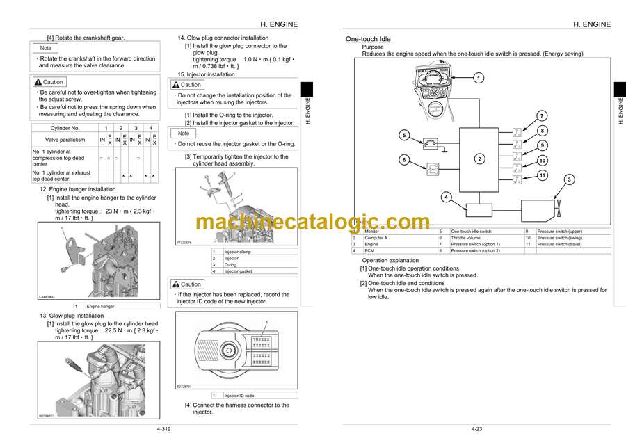
- One-touch Idle
- Auto Warm Up
- Idling Stop
- Work Mode Control
- Engine Emergency Stop
- Main Data
- Function, Structure, and Operations
- Symptom
- Engine Start Problems
- Engine Stalling
- Engine Hunting, Rough Idling
- Excess Amount of White Smoke in Exhaust Gas
- Excess Amount of Black Smoke in Exhaust Gas
- Abnormal Noise
- Large fuel consumption
- Large oil consumption
- Engine Output Deficiency
- Functional Inspection
- Start Circuit System Inspection
- Engine Compression Pressure Inspection
- Starting System Inspection
- Inspection of the fuel system
- Inspection of the air intake system
- Inspection of the exhaust system
- Inspection of EGR Control System
- Glow Control System Inspection
- OBD System Check
- Monitor Warning Light Lighting Circuit System Inspection
- Monitor Warning Light Flashing Circuit System Inspection
- Inspection of Scan Tool Power Supply System
- Maintenance precautions
- Removal and Installation of Engine Assembly
- Removal of Engine Assembly
- Installation of Engine Assembly
- Removal and Installation of Fuel Cooler, Engine Intercooler, Radiator, and Oil Cooler
- Removal and Installation of Fuel Cooler
- Removal and Installation of Engine Intercooler
- Removal and Installation of Radiator
- Removal and Installation of Oil Cooler
- Removal and Installation of Turbocharger assembly
- Turbocharger assembly removal
- Turbocharger assembly installation
- Removal and Installation of EGR Valve
- Removal of EGR Cooler and EGR Valve
- Installation of EGR Cooler and EGR Valve
- Removal and Installation of Engine Hood
- Removal of Engine Hood
- Installation of Engine Hood
- Removal and Installation of Muffler
- Removal of Muffler
- Installation of Muffler
- Removal and Installation of Cylinder Head Cover
- Cylinder head cover removal
- Installation of Cylinder Head Cover
- Removal and Installation of Cylinder Head
- Removal and Installation of Idle gear
- Removal of Idle gear
- Installation of Idle gear
- Inspection
- Removal and Installation of Cylinder Block
- Removal of Cylinder Block
- Installation of Cylinder Block
- Inspection
- Lubrication System
- Removal and Installation of Oil Pan
- Removal and Installation of Oil Pump Assembly
- Engine oil Inspection
- Cooling System
- Removal and Installation of Water Pump Assembly
- Removal and Installation of Thermostat
- InspectionInspection of Coolant
- Inspection of Cooling Fan Belt
- Removal and Installation of Exhaust Manifold
- Removal of Exhaust Manifold
- Installation of Exhaust Manifold
- Disassembly, Removal and Installation of Crankshaft
- Removal of Crankshaft
- Installation of Crankshaft
- Disassembly of Crankshaft
- Assembly of Crankshaft
- Inspection
- Disassembly, Removal and Installation of Piston
- Removal of Piston
- Installation of Piston
- Disassembly of Piston
- Assembly of Piston
- Inspection
- Removal and Installation of Camshaft
- Removal of Camshaft
- Installation of Camshaft
- Inspection
- Removal and Installation of Flywheel
- Removal of Flywheel
- Installation of Flywheel
- Inspection
- Removal and Installation of Crankshaft front oil seal
- Removal of Crankshaft front oil seal
- Installation of Crankshaft front oil seal
- Removal and Installation of Crankshaft rear oil seal
- Removal of Crankshaft rear oil seal
- Installation of Crankshaft rear oil seal
- Removal and Installation of Rocker arm shaft
- Removal of Rocker arm shaft
- Installation of Rocker arm shaft
- Inspection
- Removal and Installation of Valve spring
- Removal of Valve spring
- Installation of Valve spring
- Inspection
- Removal and Installation of Valve stem oil seal
- Removal of Valve stem oil seal
- Installation of Valve stem oil seal
- Removal and Installation of Intake chamber
- Removal of Intake chamber
- Installation of Intake chamber
- Removal and Installation of Integrated oxidation catalyst silencer
- Removal of Integrated oxidation catalyst silencer
- Installation of Integrated oxidation catalyst silencer
- Removal and Installation of Generator
- Removal of Generator
- Installation of Generator
- Inspection
- Removal and Installation of Fuel Tank
- Removal of Fuel Tank
- Installation of Fuel Tank
- Removal and Installation of Fuel Supply Pump
- Removal of Fuel Supply Pump
- Installation of Fuel Supply Pump
- Removal and Installation of Common Rail Assembly
- Removal of Common Rail Assembly
- Installation of Common Rail Assembly
- Removal and Installation of Injector
- Removal of Injector
- Installation of Injector
- Removal and Installation of Starter Motor
- Removal of Starter Motor
- Installation of Starter Motor
- Removal and Installation of Alternator
- Removal of Alternator
- Installation of Alternator
- Preheating System
- Removal and Installation of Glow Plug
- Introduction to the trouble diagnosis
- Removal and Installation of Suction Control Valve
- Removal and Installation of Pressure limiter
- Removal and Installation of Fuel filter pressure
- Removal and Installation of Fuel temperature sensor
- Removal and Installation of Fuel pressure sensor
- Removal and Installation of Engine coolant temperature sensor
- Removal and Installation of CKP sensor
- Removal and Installation of CMP sensor
- Removal and Installation of Engine speed sensor
- Removal and Installation of Oil pressure sensor
- Removal and Installation of Pressure sensor/boost temperature sensor
- Removal and Installation of IMT sensor
- Engine-side Diagnostic Trouble Code List
- Diagnostic Trouble Code Display on the Front Screen
- Troubleshooting – engine
- Engine-side Trouble
- J. HYDRAULIC EQUIPMENT (PUMP, OPERATION SYSTEM VALVE)
- Main Equipment Table
- Basic Functions
- Oil Temperature Gauge
- Static Horsepower Control
- Pump horsepower boost control
- Solenoid Sticking Prevention
- Hot Shutdown Warning
- Breaker Mode/Crusher Mode
- Port Diagram
- Hydraulic Pump
- Control Valve
- 3 Stack Solenoid Valve
- 2 Stack Solenoid Valve
- Remote Control Valves (upper, travel)
- Cushion Valve
- 2-way Selector Valve
- Direction Valve
- Shut-off Valve
- Manifold Under Cab
- Manifold (accumulator section)
- Manifold (hydraulic tank section)
- Hydraulic Device
- Main Equipment Structure and Operation Explanation
- Control valve
- 3 Stack Solenoid Valve Operation Explanation
- External Shape Diagram and Component Parts
- Operation Explanation
- Upper Pilot Valve (remote control valve)
- Structure
- Function
- Operation
- Structural Diagram
- Travel Pilot Valve (remote control valve)
- Operation
- Structural Diagram
- Cushion Valve
- Structure
- Operation Explanation
- Pressure Bleeding Operations
- Removal and Installation of Hydraulic Tank
- Removal of Hydraulic Tank
- Installation of Hydraulic Oil Tank
- Removal and Installation of Hydraulic Pump
- 80X3
- Removal of Hydraulic Pump
- Installation of hydraulic pump
- Removal and Installation of Pump Coupling
- Removal of Pump Coupling
- Installation of Pump Coupling
- Removal and Installation of Control Valve
- Removal of Control Valve
- Installation of Control Valve
- Removal and Installation of Pilot Blocs
- Removal and Installation of Travel Remote Control Valve
- Removal of Travel Remote Control Valve
- Installation of Travel Remote Control Valve
- Removal and Installation of Operation Remote Control Valve
- Removal of Operation Remote Control Valve (left side)
- Installation of Operation Remote Control Valve (left side)
- Removal of Operation Remote Control Valve (right side)
- Installation of Operation Remote Control Valve (right side)
- Removal and Installation of 3 Stack Solenoid
- Removal of 3 Stack Solenoid
- Installation of 3 Stack Solenoid Valve
- Removal and Installation of Cushion Valve
- Removal of Cushion Valve
- Installation of Cushion Valve
- Reverse Prevention Valve
- Troubleshooting
- Tools Used
- Disassembling instructions
- Assembling instructions
- Breakdown Diagram
- Operation Explanation
- Procedures for Assembly and Disassembly of Hydraulic Pump Main Unit
- Tools
- Disassembly procedures
- Assembly Procedures
- Pump Main Unit Maintenance Standards
- Replacement Standards of Worn Part
- Standards for repairing cylinders, valve plates, and swash plates (shoe plates)
- Tightening torque
- Overall View
- Procedures for Assembly and Disassembly of Control Valve
- Disassembly
- Assembly
- Installation
- Run
- Control Valve Specifications List
- Troubles and Countermeasures
- Internal Structure Diagram
- Procedures for Assembly and Disassembly of Operation Remote Control Valve
- Maintenance Procedures
- Disassembly Procedures
- Assembly Procedures
- Causes of Trouble and Countermeasures
- Procedures for Assembly and Disassembly of Travel Remote Control Valve
- Maintenance Procedures
- Disassembly Procedures
- Assembly Procedures
- Causes of Trouble and Countermeasures and Cross-section Diagram
- Assembly and Disassembly of Cushion Valve
- Disassembly Procedures
- Assembly Procedures
- Pressure Measurement and Adjustment Procedures
- Procedures for Pressure Measurement from the Monitor Display
- PROCEDURES FOR MEASURING HYDRAULIC OIL TEMPERATURE FROM THE MONITOR DISPLAY
- Procedures for Pressure Measurement by Installing Pressure Gauge
- Pressure Measuring Port
- Control Valve
- Pressure Measurement Preparations
- Pressure Measurement
- Main Pressure Measurement
- Pilot Pressure Measurement
- Pressure Adjustment
- Hydraulic Pump Flow Measurement Procedures
- Preparations
- Work Preparations
- Flow Measurement
- Air Bleed Procedure
- Hydraulic Equipment Layout
- Overall View
- Pump Chamber Hydraulic Equipment Layout
- Swing Body Center Section Hydraulic Equipment Layout
- Housing Left Side Hydraulic Equipment Layout
- Layout of Hydraulic Equipment in Cab
- N. CAB
- Removal and Installation of Operator’s Seat
- Removal of Operator’s Seat
- Installation of Operator’s Seat
- Removal and Installation of KAB Seat
- Removal of KAB Seat
- Installing of the KAB Seat
- Removal and Installation of Cab Assembly
- Removal of Cab Assembly
- Installation of Cab Assembly
- Removal and Installation of Wiper
- Removal of Wiper
- Installation of wiper
- Removal and Installation of Cab Front Glass
- Removal of Cab Front Glass
- Installation of Cab Front Glass
- Window Lock Adjustment Procedures
- Window Lock (front side)
- Window Lock (rear side)
- Tightening torque
- R. ELECTRICAL PARTS
- Electrical and Engine Functions and Service Support
- Basic Functions
- Monitor Display Dimming
- Eco Gauge
- Diagnostic Trouble Code Indicator
- Clock
- Accessories
- Working Light
- Room Lamp
- Radio Mute
- Wiper and Washer
- Horn
- Back monitor
- Anti-theft
- Battery Disconnect Switch
- Reset
- Milli-amp List
- Safety
- Gate Lock
- Alternator Power Generation Detection
- Service Support
- Screen Operations
- Screen Display List
- CHECK Screen List
- List of Control Unit Screens
- SETUP Screen List
- RESET Screen List
- Setting
- Model Selection
- Engine Throttle Switch Default Setting Value
- Password Setting
- Clock Adjustment
- Parameter Setting
- Screen Brightness Setting
- Service Monitor
- How to Go to “SERVICE SUPPORT”
- General Operation on Service Monitor
- Engine Service Monitor
- Computer Explanation
- Connection Connector Pin Layout
- Computer A
- Computer B
- Monitor
- Sequence Circuit Diagram
- Code table
- Overall
- Block diagram
- Electrical Equipment Layout Diagram
- Machine Left Side Layout Diagram (radiator chamber)
- Engine Section Layout Diagram
- Main Unit Right Side Layout Diagram (pump chamber)
- Cab Layout Diagram 1
- Cab Layout Diagram 2
- Layout Around Operator Seat
- Stand Alone Parts Diagram
- Removal and Installation of Wiper Controller
- Removal of Wiper Controller
- Installation of wiper controller
- Removal and Installation of Wiper Motor
- Removal of Wiper Motor
- Installation of wiper motor
- Removal and Installation of Monitor
- Removal of Monitor
- Installation of Monitor
- ECM Replacement Procedure
- Removal and Installation of ECM
- Removal of ECM
- Installation of ECM
- Removal and Installation of Computer A
- Removal of Computer A
- Installation of Computer A
- Removal and Installation of Computer B
- Removal of Computer B
- Installation of Computer B
- Air Conditioner Overall Diagram
- Frame
- Cab
- Equipment Layout Diagram
- Circuit Diagram
- Explanation of Functions
- Actuator Inspection
- Self-diagnosis Function with Panel Display
- Part Function and Good/Poor Judgment
- Assembly and Disassembly of Unit
- Removal of inside air filter
- Removal of Blower Unit
- Replacement of Blower Motor
- Replacement of Blower Amp
- Removal of Heater Core
- Removal of Switchover BOX
- Replacement of Evaporator and Expansion Valve
- Installation of Evaporator Sensor
- Replacement of Motor Actuator
- Removal and Installation of Compressor
- Removal of Compressor
- Installation of Compressor
- Removal and Installation of Condenser
- Removal of Condenser
- Installation of Condenser
- Removal and Installation of Receiver Dryer
- Removal of Receiver Dryer
- Installation of Receiver Dryer
- Work Precautions
- Work Procedures
- Filling Procedures
- V. ATTACHMENTS
- Main Equipment Table
- Maintenance Standards
- Removal and Installation of Bucket Cylinder
- Removal of Bucket Cylinder
- Installation of Bucket Cylinder
- Removal and Installation of Arm Cylinder
- Removal of Arm Cylinder
- Installation of Arm Cylinder
- Removal and Installation of Boom Cylinder
- Removal of Boom Cylinder
- Installation of Boom Cylinder
- Removal and Installation of Boom Swing Cylinder
- Removal of Boom Swing Cylinder
- Installation of Boom Swing Cylinder
- Procedures for Operation/Assembly and Disassembly of Hydraulic Cylinder (made by KYB)
- Specifications and Structure Diagram (including the assembly diagram and parts table)
- Handling Precautions
- Storage Standards
- Assembly and Disassembly Procedures
- Structural Diagram
- Port Diagram
- Removal and Installation of HBCV
- Removal and Installation of Arm HBCV
- Removal and Installation of Boom HBCV
- Air Bleed Procedure
- Removal and Installation of Bucket
- Removal of Bucket
- Installation of Bucket
- Removal and Installation of Bucket Link
- Removal of Bucket Link
- Installation of Bucket Link
- Removal and Installation of Arm
- Removal of Arm
- Installation of Arm
- Removal and Installation of Boom
- Removal of Boom
- Installation of Boom
- Z. OTHER
- Specifications
- Arm Dimension
- Standard Arm [1.69 m (5.5446 ft.)]
- Long Arm [2.19 m (7.1850 ft.)]
- Main Unit Weight
- Bolt Size and Torque Table
- Overall View
- WORK RANGE DIAGRAM
- New Machine Performance Judgment Table
- Table of Standards
- Measurement Method
- FLUIDS AND LUBRICANTS
- HYDRAULIC FLUID
- Engine Oil
- Oil Grade
- FUEL
- Conditions applicable to diesel fuel
- Recommended Conditions That Can Be Applied To Diesel Fuel
- Main Unit-side Diagnostic Trouble Code List
- Main Unit-side Trouble
- Diagnostic Trouble Code: 7000 P1 Pressure Sensor Signal Abnormality
- Diagnostic Trouble Code: 7001 P2 Pressure Sensor Signal Abnormality
- Diagnostic Trouble Code: 7004 Bottom Pressure Sensor Signal Abnormality
- Diagnostic Trouble Code: 7040 Fuel Level Sensor Signal Abnormality
- Diagnostic Trouble Code: 7041 Oil Temperature Sensor Signal Abnormality
- Diagnostic Trouble Code: 7200 Swing Brake Solenoid Signal Abnormality
- Diagnostic Trouble Code: 7201 Travel High-speed Solenoid Signal Abnormality
- Diagnostic Trouble Code: 7203 Travel Alarm Buzzer Signal Abnormality
- Diagnostic Trouble Code: 7206 Option Line Switchover Solenoid Signal Abnormality
- Diagnostic Trouble Code: 7207 Free Swing Solenoid Signal Abnormality
- Diagnostic Trouble Code: 7210 Liftcrane Buzzer Signal Abnormality
- Diagnostic Trouble Code: 7211 Rotating Light and Bucket Lock Relay Signal Abnormality
- Diagnostic Trouble Code: 7212 Lever Lock Solenoid Signal Abnormality
- Diagnostic Trouble Code: 7240 Pump Horsepower Proportional Valve Signal Abnormality
- Diagnostic Trouble Code: 7246 2 Pumps Flow Solenoid Signal Abnormality
- Diagnostic Trouble Code: 7254 Washer Output Abnormality
- Diagnostic Trouble Code: 7400 Abnormally High Coolant Temperature [(105°C (221.0°F) or higher)]
- Diagnostic Trouble Code: 7401 Abnormally High Coolant Temperature [ 110 °C ( 230.0 °F )or higher ]
- Diagnostic Trouble Code: 7404 Abnormally High Oil Temperature [98°C (208.4°F) or higher]
- Diagnostic Trouble Code: 7405 Abnormally High Boost Temperature [ 80 °C ( 176.0 °F )or higher ], 7406 Abnormally High Boost Temperature [ 90 °C ( 194.0 °F )or higher ]
- Diagnostic Trouble Code: 7420 Abnormally Low Alternator Voltage
- Diagnostic Trouble Code: 7421 Coolant Level Reduction
- Diagnostic Trouble Code: 7422 Abnormally Low Engine Oil Pressure
- Diagnostic Trouble Code: 7423 Air Cleaner Clogging
- Diagnostic Trouble Code: 7424 Return Filter Clogging (with breaker)
- Diagnostic Trouble Code: 7426 Fuel Filter Clogging 1
- Diagnostic Trouble Code: 7427 Fuel Filter Clogging 2
- Diagnostic Trouble Code: 7601 Monitor Communication Abnormality
- Diagnostic Trouble Code: 7602 ECM Communication Abnormality
- Diagnostic Trouble Code: 7603 Computer S Communication Abnormality
- Diagnostic Trouble Code: 7605 ECM Mismatch
- Diagnostic Trouble Code: 7606 EEPROM Data Abnormality
- Diagnostic Trouble Code: 7607 Computer C Communication Abnormality
- Diagnostic Trouble Code: 7608 Camera Abnormality
- Diagnostic Trouble Code: 7609 EEPROM (B) Data Abnormality
- Diagnostic Trouble Code: 7610 EEPROM (C) Data Abnormality
- Diagnostic Trouble Code: 7611 Computer A Communication Abnormality
- Diagnostic Trouble Code: 7612 Air Conditioner Communication Abnormality
- Diagnostic Trouble Code: 7613 Monitor Communication CAN Abnormality
- Diagnostic Trouble Code: 7614 Air Conditioner Panel Mismatch
- List of special tools
- NUMERICAL VALUE CONVERSION TABLE
- A
- C
- H
- J
- R
Link Belt


