Format: PDF (Printable Document)
File Language: English
File Pages: 1160
File Size: 80.68 MB (Speed Download Link)
Brand: Link Belt
Model: 460X2 Excavator
Type of Document: Service Text Manual
$ 40
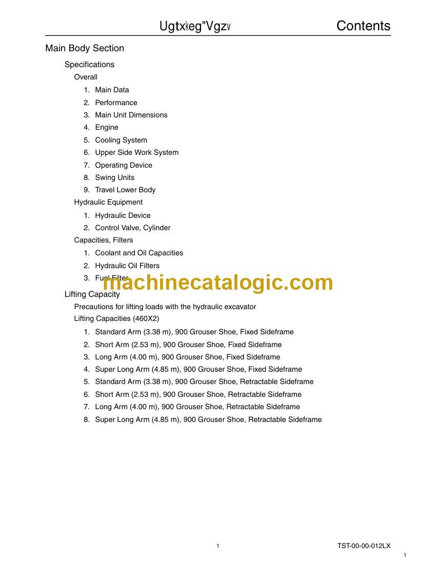
Main Body Section
Specifications
Overall
1. Main Data
2. Performance
3. Main Unit Dimensions
4. Engine
5. Cooling System
6. Upper Side Work System
7. Operating Device
8. Swing Units
9. Travel Lower Body
Hydraulic Equipment
1. Hydraulic Device
2. Control Valve, Cylinder
Capacities, Filters
1. Coolant and Oil Capacities
2. Hydraulic Oil Filters
3. Fuel Filter
Lifting Capacity
Precautions for lifting loads with the hydraulic excavator
Lifting Capacities (460X2)
1. Standard Arm (3.38 m), 900 Grouser Shoe, Fixed Sideframe
2. Short Arm (2.53 m), 900 Grouser Shoe, Fixed Sideframe
3. Long Arm (4.00 m), 900 Grouser Shoe, Fixed Sideframe
4. Super Long Arm (4.85 m), 900 Grouser Shoe, Fixed Sideframe
5. Standard Arm (3.38 m), 900 Grouser Shoe, Retractable Sideframe
6. Short Arm (2.53 m), 900 Grouser Shoe, Retractable Sideframe
7. Long Arm (4.00 m), 900 Grouser Shoe, Retractable Sideframe
8. Super Long Arm (4.85 m), 900 Grouser Shoe, Retractable Sideframe
Overall View
Overall View (460X2)
1. Standard Arm (3.38 m) / Fixed Sideframe
2. Short Arm (2.53 m) / Fixed Sideframe
3. Long Arm (4.00 m) / Fixed Sideframe
4. Super Long Arm (4.85 m) / Fixed Sideframe
5. Standard Arm (3.38 m) / Retractable Sideframe
6. Short Arm (2.53 m) / Retractable Sideframe
7. Long Arm (4.00 m) / Retractable Sideframe
8. Super Long Arm (4.85 m) / Retractable Sideframe
Work Range Diagram
Work Range Diagram (460X2)
1. Standard Arm (3.38 m) / Fixed Sideframe
2. Short Arm (2.53 m) / Fixed Sideframe
3. Long Arm (4.00 m) / Fixed Sideframe
4. Super Long Arm (4.85 m) / Fixed Sideframe
5. Standard Arm (3.38 m) / Retractable Sideframe
6. Short Arm (2.53 m) / Retractable Sideframe
7. Long Arm (4.00 m) / Retractable Sideframe
8. Super Long Arm (4.85 m) / Retractable Sideframe
Summary Section
Main Equipment Table
Lower Component
1. Travel Unit
2. Take-up Roller
3. Upper Roller
4. Lower Roller
5. Recoil Spring
6. Shoe
Upper Component
1. Swing Unit
Engine-related
1. Engine
2. Muffler
3. Air Cleaner (double element)
4. Radiator
Hydraulic Device
1. Hydraulic Pump
2. Pump P-Q Diagram
Control-related
1. Control Valve
2. Solenoid Valve (5 stack)
3. Remote Control Valve (left/right, travel operations)
4. Remote Control Valve Characteristic Diagram
5. Cushion Valve (with shuttle valve)
6. Selector Valve
7. Center Joint
Backhoe Attachment
1. Cylinder
2. Attachments
Equipment Layout Diagram
Main Equipment Layout
Consumable Part Layout
Standard Machine Option List
List of Optional Components
Hydraulics Section
Hydraulic Equipment Layout
Overall View
Pump Chamber Hydraulic Equipment Layout
Swing Body Center Section Hydraulic Equipment Layout
Housing Left Side Hydraulic Equipment Layout
Layout of Hydraulic Equipment in Cab
Port Diagram
Pump
1. Hydraulic Pump (standard model)
Valves
1. Control Valve
2. 5 Stack Solenoid Valve
3. 2 Stack Solenoid Valve
4. Remote Control Valves (upper, travel)
5. Cushion Valve
6. 2-way Multi-valve
7. HBCV (Arm)
8. HBCV (Boom)
Manifolds
1. Manifold Under Cab
2. Manifold (accumulator section)
3. Manifold
Motors
1. Swing Motor
2. Travel Motor
3. Center Joint
Pilot Hose Connection Diagram
Pilot P and T Lines
Pilot Control Line
Pilot Control Line (2-way selector valve)
Function List
Function Table
Explanation of New Functions
1. Swing Relief Cut-off Control
2. Option Line Flow Adjustment Control
3. Bucket-close Regenerative Circuit
Explanation of Hydraulic Circuit and Operations (standard model)
Travel Circuit
Travel Low-speed Circuit
Travel High-speed Circuit
Straight Travel Circuit
Swing Circuit
Swing Relief Cut-off Control Circuit
Swing Priority Circuit
Swing Brake Circuit
Swing Parking Circuit (lever in neutral)
Swing Parking Circuit (brake release)
Swing Parking Circuit (machine stop)
Boom Circuit
Boom-up Circuit (independent operation) (with/without HBCV)
Boom-up Circuit (compound boom up + arm in) (with/without HBCV)
Boom-down Regenerative Circuit (with/without HBCV)
Boom-down Tilting Prevention Circuit
Boom-down Load Holding Valve Circuit
Arm Circuit
Arm-out Circuit (with/without HBCV)
Arm-in Forced Regenerative Circuit
Arm-in load holding valve circuit
Bucket Circuit
Bucket-open Circuit
Bucket-close Regenerative Circuit
Negative Control Circuit
Negative Control Circuit
Other Circuits
Cushion Circuit (arm-out operation)
Cushion Circuit (when arm-out operation stopped)
Cushion Circuit (arm-out → arm-in operation)
Heat Circuit (lever in neutral)
Auto Pressure Boost Circuit (bucket close)
Explanation of Hydraulic Circuit and Operations (option)
Option Circuits
Breaker Circuit (independent operation)
Double-acting Circuit (hydraulic fork)
Multi-purpose Circuit (breaker circuit)
Multi-purpose Circuit (2 pumps flow crusher)
2nd Option Circuit (hydraulic rotation fork)
Hydraulics Section
Hydraulic Equipment Layout
Overall View
Pump Chamber Hydraulic Equipment Layout
Swing Body Center Section Hydraulic Equipment Layout
Housing Left Side Hydraulic Equipment Layout
Layout of Hydraulic Equipment in Cab
Port Diagram
Pump
1. Hydraulic Pump (standard model)
Valves
1. Control Valve
2. 5 Stack Solenoid Valve
3. 2 Stack Solenoid Valve
4. Remote Control Valves (upper, travel)
5. Cushion Valve
6. 2-way Multi-valve
7. HBCV (Arm)
8. HBCV (Boom)
Manifolds
1. Manifold Under Cab
2. Manifold (accumulator section)
3. Manifold
Motors
1. Swing Motor
2. Travel Motor
3. Center Joint
Pilot Hose Connection Diagram
Pilot P and T Lines
Pilot Control Line
Pilot Control Line (2-way selector valve)
Function List
Function Table
Explanation of New Functions
1. Swing Relief Cut-off Control
2. Option Line Flow Adjustment Control
Explanation of Hydraulic Circuit and Operations (standard model)
Travel Circuit
Travel Low-speed Circuit
Travel High-speed Circuit
Straight Travel Circuit
Swing Circuit
Swing Relief Cut-off Control Circuit
Swing Priority Circuit
Swing Brake Circuit
Swing Parking Circuit (lever in neutral)
Swing Parking Circuit (brake release)
Swing Parking Circuit (machine stop)
Boom Circuit
Boom-up Circuit (independent operation) (with/without HBCV)
Boom-up Circuit (compound boom up + arm in) (with/without HBCV)
Boom-down Regenerative Circuit (with/without HBCV)
Boom-down Tilting Prevention Circuit
Boom-down Load Holding Valve Circuit
Arm Circuit
Arm-out Circuit (with/without HBCV)
Arm-in Forced Regenerative Circuit
Arm-in load holding valve circuit
Bucket Circuit
Bucket-open Circuit
Bucket-close Regenerative Circuit
Negative Control Circuit
Negative Control Circuit
Other Circuits
Cushion Circuit (arm-out operation)
Cushion Circuit (when arm-out operation stopped)
Cushion Circuit (arm-out → arm-in operation)
Heat Circuit (lever in neutral)
Auto Pressure Boost Circuit (bucket close)
Explanation of Hydraulic Circuit and Operations (option)
Option Circuits
Breaker Circuit (independent operation)
Double-acting Circuit (hydraulic fork)
Multi-purpose Circuit (breaker circuit)
Multi-purpose Circuit (2 pumps flow crusher)
2nd Option Circuit (hydraulic rotation fork)
Electrics Section
Explanation of New Functions
Work Mode Select Switch
The Throttle Volume and Work Mode Select Switch are Linked!!
Computer connection method
Monitor changes
Pilot pressure switch changed to pressure sensor
Pump Electromagnetic Proportional Valve
1. Horsepower Control Proportional Valve
2. P1 Flow Control Proportional Valve
System Control for Energy Saving
1. Reduced Fuel Consumption Through Transient Load Reduction Control
2. Reduced Fuel Consumption Through Swing Relief Cut Control
Electrical Equipment Layout Diagram
Overall View
1. Main Unit Left Side Layout Diagram (radiator chamber)
2. Engine Section Layout Diagram
3. Engine Section Layout Diagram
4. Main Unit Center Section Layout Diagram
5. Cab Layout Diagram 1
6. Layout Around Operator’s Seat
Stand Alone Parts Diagram
Main Equipment Structural Diagrams
Connection Connector Pin Layout
1. Computer A
2. Monitor
Electrical Circuit Diagram
Overall View
1. Sequence Circuit Diagram
Block Diagram
1. Computer A
2. Computer S
3. ECM
4. Monitor Display
5. Air Conditioner
6. Lever Lock
7. Horn
8. Working Light


