Format: PDF (Printable Document)
File Language: English
File Pages: 1075
File Size: 80.64 MB (Speed Download Link)
Brand: Link Belt
Model: 160X2 Excavator
Type of Document: Service Text Manual
$ 40
Specifications
Overall
1. Main Data
2. Performance
3. Main Body Dimensions
4. Engine
5. Cooling System
6. Upper Side Work System
7. Operating Device
8. Swing Units
9. Travel Lower Body
Hydraulic Equipment
1. Hydraulic Device
2. Control Valve, Cylinder
Capacities, Filters
1. Water and Oil Capacities
2. Hydraulic Oil Filters
3. Fuel Filter
Lifting Capacity
Precautions for lifting loads with the hydraulic excavator
Lifting Capacities
Overall View
Overall View (160X2)
1. Standard Arm (2.62 m)
2. Long Arm (3.05 m)
Work Range Diagram
Work Range Diagram (160X2)
1. Standard Arm (2.62 m)
2. Long Arm (3.05 m)
Summary Section
Main Equipment Table
Lower Component
1. Travel Unit
2. Take-up Roller
3. Upper-roller
4. Lower-roller
5. Recoil Spring
6. Shoes
Upper Component
1. Swing Unit
Engine-related
1. Engine
2. Muffler
3. Air Cleaner (double element)
4. Radiator
Hydraulic Device
1. Hydraulic Pump
2. Pump P – Q Diagram
Control-related
1. Control Valve
2. Solenoid Valve (5-stack)
3. Remote Control Valve (left / right, travel operations)
4. Remote Control Valve Characteristic Diagram
5. Cushion Valve (heat circuit, with shuttle valve)
6. Selector Valve (option)
7. Center Joint
Backhoe Attachment
1. Cylinder
2. Attachment
Equipment Layout Diagram
Main Equipment Layout
Consumable Part Layout
Standard Machine Option List
List of Optional Components
Hydraulics Section
Hydraulic Equipment Layout
Overall View
Pump Chamber Hydraulic Equipment Layout
Swing Body Center Section Hydraulic Equipment Layout
Housing Left Side Hydraulic Equipment Layout
Layout of Hydraulic Equipment in Cab
Port Diagram
Pump
1. Hydraulic Pump (standard model)
Valves
1. Control Valve
2. 5-stack Solenoid Valve
3. 2-stack Solenoid Valve
4. Remote Control Valves (upper side, travel)
5. Cushion Valve
6. 2-way Multi-valve
7. Direction Valve / Shut-off Valve
8. HBCV
Manifolds
1. Manifold Under Cab
2. Manifold (accumulator section)
3. Manifold (hydraulic oil tank section)
Motors
1. Swing Motor
2. Travel Motor
3. Center Joint
Pilot Hose Connection Diagram
Pilot P and T Lines
Pilot Control Line
Pilot Control Line (2-way selector valve)
Pilot Control Line (4-way selector valve) (Not used by LBX)
Function List
Function Table
Explanation of New Functions
1. Swing Relief Cut Control
2. Negative Control Power Save Control
3. Option Line Flow Adjustment Control
4. Multi Purpose Circuit (breaker ⇔ crusher) One-touch Switching Control
5. Bucket-close Regenerative Circuit
Explanation of Hydraulic Circuit and Operations (standard model)
Travel Circuits
1. Travel Low-speed Travel Circuit
2. Travel High-speed Travel Circuit
3. Straight Travel Circuit
Swing Circuits
1. Swing Relief Cut-off Control Circuit
2. Swing Priority Circuit
3. Swing Brake Circuit
4. Swing Parking Circuit (lever in neutral)
5. Swing Parking Circuit (brake release)
6. Swing Parking Circuit (machine stop)
Boom Circuits
1. Boom-up Circuit (single operation)
2. Boom-up Circuit (compound boom-up + arm-in)
3. Boom-down Regenerative Circuit
4. Boom-down Tilting Prevention Circuit
5. Boom-down Load Hold Valve Circuit
Arm Circuits
1. Arm-out Circuit
2. Arm-in Forced Regenerative Circuit
3. Arm-in Load Hold Valve Circuit
Bucket Circuit
1. Bucket-open Circuit
2. Bucket-close Regenerative Circuit
Negative Control Circuit
1. Negative Control Circuit (power save solenoid OFF)
2. Negative Control Power Save Circuit (power save solenoid ON)
3. Negative Control Circuit (bucket close, power save solenoid OFF)
Horsepower Boost Circuits
1. Arm-in Horsepower Boost Circuit
2. Travel Horsepower Boost Circuit
Other Circuits
1. Cushion Circuit
(1) Arm-out Operation
(2) Arm-out Operation Stopped
(3) Arm-out → Arm-in Operation
2. Heat Circuit (lever in neutral)
3. Auto Pressure Boost Circuit (bucket close)
Explanation of Hydraulic Circuit and Operations (option)
Option Circuit
1. Breaker Circuit (single operation)
2. Shuttle Circuit (hydraulic fork)
3. Multi Purpose Circuit
(1) Breaker Q Control
(2) 2 Pumps Flow Crusher
4. 2nd Option Circuit (hydraulic rotation fork)
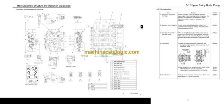
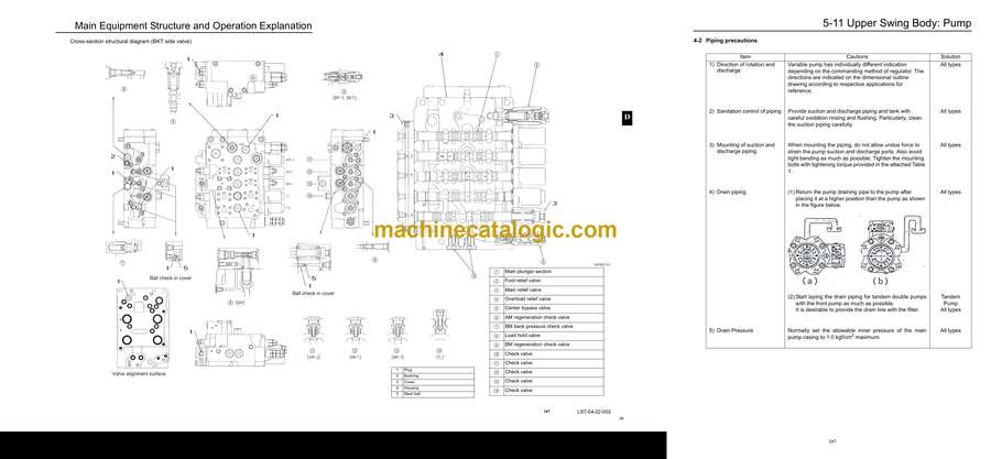
Main Equipment Structure and Operation Explanation
Pump
1. Hydraulic Pump
2. Regulator
3. Gear Pump
Motor
1. Travel Motor
2. Swing Motor
Valve
1. Control Valve
2. 5-stack Solenoid Valve Operation Explanation
3. Upper Pilot Valve (remote control valve)
4. Travel Pilot Valve (remote control valve)
5. Cushion Valve
6. Selector Valve (3-direction)
7. HBCV Holding Valve
Electrics Section
Explanation of New Functions
Work Mode Select Switch
Computer Connection Method
Monitor Changes
Pilot Pressure Switch Changed to Pressure Sensor
Pump Electromagnetization Proportion Valve
1. Horsepower Control Proportional Valve
2. P1 Flow Control Proportional Valve
System Control for Energy Saving
1. Reduced Fuel Consumption Through Transient Load Reduction Control
2. Reduced Fuel Consumption Through Swing Relief Cut Control
3. Reduced Fuel Consumption Through Power Save Control
Swing Speed Limit Control
Electrical Equipment Layout Diagram
Overall View
1. Main Unit Left Side Layout Diagram (radiator chamber)
2. Engine Section Layout Diagram
3. Main Unit Right Side Layout Diagram (pump chamber)
4. Main Unit Center Section Layout Diagram
5. Cab Layout Diagram 1
6. Layout Around Operator Seat
Stand-alone Parts Diagram
Main Equipment Structural Diagrams
Connection Connector Pin Layout
1. Computer
2. Monitor
Electrical Circuit Diagram
Overall View
1. Sequence Circuit Diagram (A3)
Block Diagram
1. Computer
2. Computer S (Not used by LBX)
3. ECM
4. Monitor Display
5. Air Conditioner
6. Lever Lock
7. Horn
8. Working Light
9. Option
10. Others
11. Electrical Symbol List
Electrical Connector Wiring Diagram
Main Frame
1. Main Frame
Cab
1. Cab Main Harness
2. Cab Sub Harness
3. In Cab
Console
1. Console Right Harness
2. Console Left Harness
Electrical Parts and Wiring Assembly Diagram
Main Frame
Cab
Explanation of Functions and Operations
Explanation of Electrical Functions
Engine Speed Control
1. Throttle Control
2. Idling Control (auto / one-touch)
3. Idling Start
4. Idle Up
5. Auto Warm Up
Engine Start / Stop Control
1. Engine Start / Stop Judgment
2. Power-cut Delay
3. Engine Emergency Stop
4. Neutral Start
Pump Control
1. Work Mode Control
2. Pump Added Horsepower Control
3. Pump Horsepower Cut Control
4. Power Save Control
Swing
1. Swing Brake
2. Swing Lock (for maintenance)
3. Swing Relief Cut
4. Swing Speed Limit
Travel
1. Travel Speed Switchover
2. Travel Alarm
Valve Control
1. Lever Lock
2. Solenoid Sticking Prevention
3. Pressure Boost Control
Monitor Control
1. Bar Graph
(coolant temperature gauge, oil temperature gauge, fuel gauge)
Accessories
1. Horn
2. Working Light
3. Wiper & Washer
4. Room Lamp
5. Radio Mute
Others
1. Anti-theft Protection
2. Battery Save Function
3. Alternator Power Generation Detection
4. Overload Alarm (Not used by LBX)
Options
1. Option Line Control
2. Option Line Control
3. Feed Pump Automatic Stop
4. Return Filter Clogging Detected
Service Support
Screen Operations
1. Screen Shift
Screen Display List
1. CHK (status display) Screen List
2. DIAG (trouble diagnosis) Screen
3. HR (usage log) Screen List
4. CFG (setting change) Screen
5. CAL (troubleshooting support) Screen
6. Check the Monitor Switch (self-diagnosis function)
7. Option Flow Setting
8. Anti-theft Setting
9. Model Setting
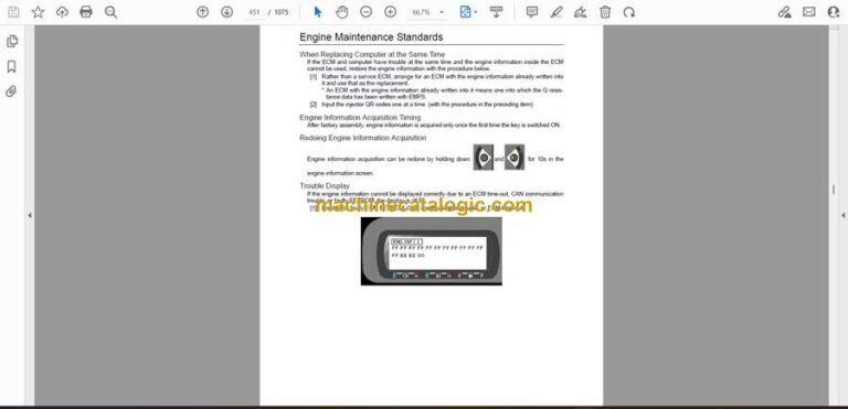
10.Engine Screen Information
Screen Display Details
1. Message Display List
Trouble Display
1. Diagnostic Trouble Code Display
2. Main Unit Diagnostic Trouble Code List
3. Diagnostic Trouble Code (monitor display)
4. Sensor Trouble Operation Table
5. EPF (engine protection feature)
