Link Belt 210X3 Excavator Service Manual
On a 210X3 excavator that spends its life digging foundations, loading trucks, or trenching in rough sites, this service manual is what I’d keep open on the bench or tablet. It walks you through how to approach faults methodically and how to strip and rebuild systems without guessing. If, for example, the boom feels weak or jerky, this is what I’d use to trace the hydraulic circuit, test pressures in the right order, and confirm whether it’s a control issue, a valve problem, or a worn component before I touch a wrench.
Applications & Use Cases
- Track down hydraulic problems by following step-by-step checks instead of swapping parts blindly.
- Plan disassembly and reassembly of major components so hoses, shims, and brackets go back exactly as they came off.
- Verify adjustments on controls and linkages after a repair so the machine responds smoothly and predictably.
- Confirm what to inspect during scheduled services to catch leaks, wear, or misalignment early.
- Support field diagnostics when an operator reports noises, slow cycles, or warning lights.
FAQ
Q: Can I use this on a tablet at the jobsite?
A: Yes, it’s practical to keep it on a tablet so you can zoom into diagrams and follow procedures right next to the machine.
Q: Is it worth printing pages from this manual?
A: I’d print only the procedures or diagrams you’re using that day, mark them up with notes, and replace them if they get dirty.
Safety Note
Always lock out the machine, relieve system pressure, and secure all raised components before following any procedure from this manual.
📘 Show Index
Link Belt 210X3 Excavator Index:
- Excavator
- SAFETY
- Safety, general information and standard torque data
- General Information
- Standard Torque Data For Cap Screws And Nuts
- A. LOWER
- Specifications
- Main Equipment Table
- Main Equipment Structure and Operation Explanation
- Port Diagram
- Travel Motor
- Center Joint
- Basic Functions
- Travel Speed Selection
- Travel Alarm
- Removal and Installation of Track
- Removal and Installation of Shoe Assembly
- Removal and Installation of Shoe Plate
- Removal and Installation of Roller
- Removal and Installation of Upper Roller
- Assembly and Disassembly of Upper Roller
- Removal and Installation of Lower Roller
- Assembly and Disassembly of Lower Roller
- Removal and Installation of Drive Sprocket
- Removal of Drive Sprocket
- Installation of Drive Sprocket
- Removal and Installation of Take-up Roller
- Removal of Take-up Roller
- Installation of Take-up Roller
- Assembly and Disassembly of Take-up Roller
- Configuration Diagram
- Dimension Diagram
- Jig Dimension Diagram
- Disassembly Procedures
- Assembly Procedures
- Removal and Installation of Grease Cylinder
- Removal of grease cylinder
- Installation of grease cylinder
- Assembly and Disassembly of Tension Shock Absorber
- Configuration Diagram
- Dimension diagram
- Jig dimension diagram
- Disassembly procedures
- Assembly procedures
- Removal and Installation of Center Joint
- Removal of Center Joint
- Installation of Center Joint
- Assembly and Disassembly of Center Joint
- Configuration Diagram
- Dimension Diagram
- Jig Dimension Diagram
- Disassembly Procedures
- Assembly Procedures
- Removal and Installation of Travel Motor
- Removal of Travel Motor
- Installation of Travel Motor
- Assembly and Disassembly of Travel Motor
- Tools for Assembly and Disassembly
- Motor Disassembly Procedures
- Maintenance Standards
- Motor Assembly Procedures
- Troubleshooting
- Structural Diagram
- Maintenance Standards
- Drive sprocket
- Take-up roller
- Upper roller
- Lower Roller
- Track Shoe (Grouser Shoe)
- Inspection Gauge
- Pressure Measurement and Adjustment Procedures
- Main Pressure Measurement
- Drain Volume Measurement Procedures
- Preparations
- Travel Motor Drain Volume Measurement
- Air Bleed Procedure
- B. C. SWING UNIT, COUNTERWEIGHT
- Specifications
- Main Equipment Table
- Main Equipment Structure and Operation Explanation
- Port Diagram
- Basic Functions
- Swing Brake
- Swing Lock
- Swing Speed Limit
- Free Swing (option)
- Removal and Installation of Swing Unit
- Removal of Swing Unit
- Installation of Swing Unit
- Assembly and Disassembly of Swing Motor
- Causes of Trouble and Solutions
- Maintenance Standard Table
- Required Tools
- Jig
- Disassembly
- Assembly
- Swing Motor Internal Structure Diagram
- Assembly and Disassembly of Swing Unit
- Assembly and Disassembly of Swing Reduction Gear
- Disassembly
- Assembly
- Jig
- Swing Reduction Gear Structure Diagram
- Removal and Installation of Counterweight
- Removal of Counterweight
- Installation of Counterweight
- Pressure Measurement and Adjustment Procedures
- Main Pressure Measurement
- Drain Volume Measurement Procedures
- Preparations
- Swing Motor Drain Volume Measurement
- Air Bleed Procedure
- H. ENGINE
- Specifications
- Main Equipment Table
- Basic Functions
- Fuel Gauge
- Coolant Temperature Gauge
- DPD Gauge
- Fuel Economy Gauge
- Neutral Start
- Engine Start/Stop Control
- Power-cut Delay
- Preheating
- Throttle
- Engine Throttle Switch Position Detection
- Idling Start
- Auto Idle
- One-touch Idle
- Auto Warm Up
- Quick Warm Up
- Idling Stop
- Idle up
- Work Mode Control
- Engine Emergency Stop
- Main Data
- Function, structure, and operations
- Symptom
- Frequent Manual DPD Regeneration
- DPD Regeneration Taking Excessively Long
- Engine Start Problems
- Engine Stalling
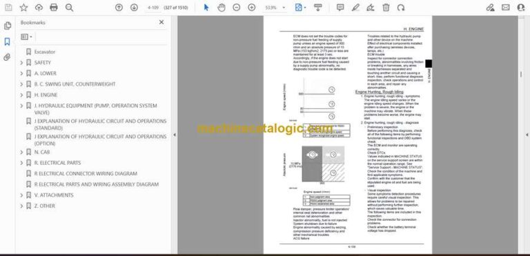
- Engine Hunting, Rough Idling
- Excess Amount of White Smoke in Exhaust Gas
- Excess Amount of Black Smoke in Exhaust Gas
- Abnormal Noise
- High Fuel Consumption
- High Oil Consumption
- Engine Output Deficiency
- Functional Inspection
- Inspection of Scan Tool Power Supply System
- Start Circuit System Inspection
- Engine Compression Pressure Inspection
- Start System Inspection
- Fuel System Inspection
- Suction air system inspection
- Exhaust system inspection
- Inspection of EGR Control System
- Glow Control System Inspection
- DPD Function Inspection
- OBD System Check
- Inspection of the monitor warning light illumination circuit system
- Inspection of the monitor warning light blinking circuit system
- Maintenance precautions
- Removal and Installation of Engine Assembly
- Removal of Engine Assembly
- Installation of Engine Assembly
- Removal and Installation of Fuel Cooler, Engine Intercooler, Radiator, and Oil Cooler
- Removal and Installation of Fuel Cooler
- Removal and Installation of Engine Intercooler
- Removal and Installation of Radiator
- Removal and Installation of Oil Cooler
- Removal and Installation of Turbo Charger
- Turbocharger assembly Removal
- Turbocharger assembly Installation
- Removal and Installation of EGR Valve
- EGR valve Removal
- EGR valve Installation
- Removal and Installation of Engine Hood
- Removal of Engine Hood
- Installation of Engine Hood
- Removal and Installation of Muffler
- Removal of Muffler
- Installation of Muffler
- Removal and Installation of Cylinder Head Cover
- Cylinder head cover Removal
- Installation of Cylinder Head Cover
- Removal and Installation of Cylinder Head
- Removal and Installation of Cylinder Block
- Removal of Cylinder Block
- Installation of Cylinder Block
- Inspection
- Lubrication System
- Removal and Installation of Oil Pan
- Removal and Installation of Oil Level Switch
- Removal and Installation of Oil Pump Assembly
- Engine oil Inspection
- Removal and Installation of Oil Port Cover
- Cooling System
- Removal and Installation of Water Pump Assembly
- Removal and Installation of Thermostat
- Inspection of Coolant
- Inspection of Cooling Fan Belt
- Removal and Installation of Overheat Switch
- Removal and Installation of Exhaust Manifold
- Removal of Exhaust Manifold
- Installation of Exhaust Manifold
- Inspection
- Disassembly, Removal and Installation of DPD Assembly
- Disassembly of DPD Assembly
- Assembly of DPD Assembly
- Inspection
- Removal and Installation of Fuel Tank
- Removal of Fuel Tank
- Installation of Fuel Tank
- Removal and Installation of Fuel Supply Pump
- Removal of Fuel Supply Pump
- Installation of Fuel Supply Pump
- Removal and Installation of Common Rail Assembly
- Removal of Common Rail Assembly
- Installation of Common Rail Assembly
- Removal and Installation of Injector
- Removal of injector
- Installation of Injector
- Removal and Installation of Starter Motor
- Removal of Starter Motor
- Installation of Starter Motor
- Removal and Installation of Alternator
- Removal of Alternator
- Installation of Alternator
- Preheating System
- Removal and Installation of Glow Plug
- Introduction to the trouble diagnosis
- Removal and Installation of Suction Control Valve
- Removal and Installation of Fuel filter pressure
- Removal and Installation of Engine coolant temperature sensor
- Removal and Installation of CKP sensor
- Removal and Installation of CMP sensor
- Removal and Installation of Oil pressure sensor
- Removal and Installation of Boost sensor
- Removal and Installation of Boost temperature sensor
- Removal and Installation of IMT sensor
- Removal and Installation of Exhaust differential pressure sensor
- Removal and Installation of Exhaust gas temperature sensor
- Engine-side Diagnostic Trouble Code List
- Troubleshooting – engine
- Engine-side Trouble
- Data Reference Values
- J. HYDRAULIC EQUIPMENT (PUMP, OPERATION SYSTEM VALVE)
- Specifications
- Main Equipment Table
- Basic Functions
- Oil Temperature Gauge
- Static Horsepower Control
- Pressure Boost Control
- Pump Standby Pressure Control
- Swing Relief Cut
- Boom Down Energy Save
- Auto Energy Save
- Solenoid Sticking Prevention
- Hot Shutdown Warning
- Breaker Mode
- Crusher Mode
- Port Diagram
- Hydraulic Pump (standard model)
- Control Valve
- 5 Stack Solenoid Valve
- 2 Stack Solenoid Valve
- Remote Control Valves (upper, travel)
- Reducing Valve (3 stack)
- Cushion Valve
- 4-way Selector Valve
- 2-way Selector Valve
- Direction Valve
- Shut-off Valve
- Relief Valve (electromagnetic proportional)
- Manifold Under Cab
- Manifold (accumulator section)
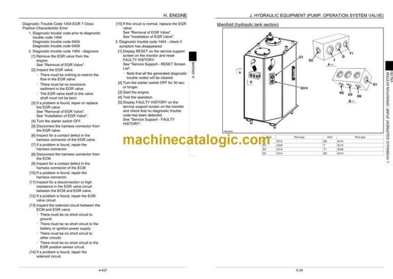
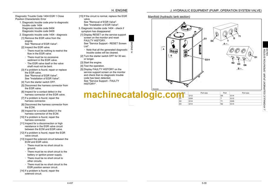
- Manifold (hydraulic tank section)
- Hydraulic Device
- Main Equipment Structure and Operation Explanation
- Control Valve
- Basic configuration
- Operation
- 5 Stack Solenoid Valve Operation Explanation
- External Shape Diagram and Component Parts
- Operation Explanation
- Upper Pilot Valve (remote control valve)
- Structure
- Function
- Operation
- Structural Diagram
- Travel Pilot Valve (remote control valve)
- Operation
- Structural Diagram
- Cushion Valve
- Structure
- Operation Explanation
- Pressure Bleeding Operations
- Removal and Installation of Hydraulic Tank
- Removal of Hydraulic Tank
- Installation of Hydraulic Oil Tank
- Removal and Installation of Hydraulic Pump
- Removal of Hydraulic Pump
- Installation of Hydraulic Pump
- Removal and Installation of Pump Coupling
- Removal of Pump Coupling
- Installation of Pump Coupling
- Removal and Installation of Control Valve
- Removal of Control Valve
- Installation of Control Valve
- Removal and Installation of Pilot Blocs
- Removal and Installation of Travel Remote Control Valve
- Removal of Travel Remote Control Valve
- Installation of Travel Remote Control Valve
- Removal and Installation of Operation Remote Control Valve
- Removal of Operation Remote Control Valve (Left)
- Installation of Operation Remote Control Valve (Left)
- Removal of Operation Remote Control Valve (right side)
- Installation of Operation Remote Control Valve (right side)
- Removal and Installation of 5 Stack Solenoid
- Removal of 5 Stack Solenoid Valve
- Installation of 5 Stack Solenoid Valve
- Removal and Installation of Cushion Valve
- Removal of Cushion Valve
- Installation of Cushion Valve
- Procedures for Assembly and Disassembly of Hydraulic Pump Main Unit
- Tools
- Disassembly procedures
- Assembly procedures
- Pump Main Unit Maintenance Standards
- Replacement standards for worn parts
- Standards for repairing cylinders, valve plates, and swash plates (shoe plates)
- Tightening torque
- Overall View
- Operation explanation
- Regulator adjustment
- Tables and diagrams
- Regulator Assembly and Disassembly Procedures
- Procedures for Assembly and Disassembly of Control Valve
- Procedures for Assembly and Disassembly of Operation Remote Control Valve
- Maintenance Procedures
- Disassembly Procedures
- Assembly Procedures
- Causes of Trouble and Countermeasures
- Procedures for Assembly and Disassembly of Travel Remote Control Valve
- Maintenance Procedures
- Disassembly Procedures
- Assembly Procedures
- Causes of Trouble and Countermeasures and Cross-section Diagram
- Assembly and Disassembly of Cushion Valve
- Disassembly Procedures
- Assembly Procedures
- Written Materials
- Pressure Measurement and Adjustment Procedures
- Procedures for Pressure Measurement from the Monitor Display
- PROCEDURES FOR MEASURING HYDRAULIC OIL TEMPERATURE FROM THE MONITOR DISPLAY
- Procedures for Pressure Measurement by Installing Pressure Gauge
- Pressure Measuring Port
- Control Valve
- Pressure Measurement Preparations
- Pressure Measurement
- Main Pressure Measurement
- Pilot Pressure Measurement
- Negative Control Pressure Measurement
- Pressure Adjustment
- Hydraulic Pump Flow Measurement Procedures
- Preparations
- Work Preparations
- Flow Measurement
- Air Bleed Procedure
- Hydraulic Equipment Layout
- Overall view
- Pump Chamber Hydraulic Equipment Layout
- SWING BODY CENTER SECTION HYDRAULIC EQUIPMENT
- HOUSING LEFT SIDE HYDRAULIC EQUIPMENT LAYOUT
- LAYOUT OF HYDRAULIC EQUIPMENT IN CAB
- J EXPLANATION OF HYDRAULIC CIRCUIT AND OPERATIONS (STANDARD)
- J EXPLANATION OF HYDRAULIC CIRCUIT AND OPERATIONS (OPTION)
- N. CAB
- Removal and Installation of Operator’s Seat
- Removal of Operator’s Seat
- Installation of Operator’s Seat
- Removal and Installation of Cab Assembly
- Removal of Cab Assembly
- Installation of Cab Assembly
- Removal and Installation of Wiper
- Removal of Wiper
- Installation of wiper
- Removal and Installation of Cab Front Glass
- Removal of Cab Front Glass
- Installation of Cab Front Glass
- Removal and Installation of Right-side Window Glass
- Removal of Right-side Window Glass
- Installation of Right-side Window Glass
- Removal and Installation of Door (Upper) Sash Glass
- Removal of Door (Upper) Sash Glass
- Installation of Door (Upper) Sash Glass
- Window Lock Adjustment Procedures
- Window Lock (front side)
- Window Lock (rear side)
- Tightening torque
- R. ELECTRICAL PARTS
- Electrical and Engine Functions and Service Support
- Basic Functions
- Monitor Display Dimming
- Eco Gauge
- Diagnostic Trouble Code Indicator
- Clock
- Accessories
- Working Light
- Room lamp
- Radio Mute
- Wiper and Washer
- Horn
- Back/Side View Monitor
- Anti-theft
- Battery Disconnect Switch
- Reset
- Milli-amp List
- Safety
- Lever Lock
- Alternator Power Generation Detection
- Setting
- Model Selection
- Throttle Volume Default Setting Value
- Password Setting
- Clock Adjustment
- Parameter Setting
- Option Flow Pressure Setting
- Screen Brightness Setting
- Service Monitor
- How to get into “Service Screen”
- General Operation on Service Monitor
- Engine Service Monitor
- Computer Explanation
- Connection Connector Pin Layout
- Computer A
- Computer B
- Monitor
- Sequence Circuit Diagram
- Code table
- Overall
- Block diagram
- Electrical Equipment Layout Diagram
- Main Unit Left Side Layout Diagram (radiator chamber)
- Engine Section Layout Diagram
- Main Unit Right Side Layout Diagram (pump chamber)
- Main Unit Center Section Layout Diagram
- Cab Layout Diagram 1
- Cab Layout Diagram 2
- Layout Around Operator Seat
- Stand Alone Parts Diagram
- Removal and Installation of Wiper Controller
- Removal of Wiper Controller
- Installation of wiper controller
- Removal and Installation of Wiper Motor
- Removal of Wiper Motor
- Installation of wiper motor
- Removal and Installation of Monitor
- Removal of Monitor
- Installation of Monitor
- ECM Replacement Procedure
- Removal and Installation of ECM
- Removal of ECM
- Installation of ECM
- Removal and Installation of Computer A
- Removal of Computer A
- Installation of Computer A
- Removal and Installation of Computer B
- Removal of Computer B
- Installation of Computer B
- Air Conditioner Overall Diagram
- Frame
- Cab
- Equipment Layout Diagram
- Circuit Diagram
- Explanation of Functions
- Actuator Inspection
- Self-diagnosis Function with Panel Display
- Part Function and Good/Poor Judgment
- Assembly and Disassembly of Unit
- Removal of Blower Unit
- Replacement of Blower Motor
- Replacement of Blower Amp
- Removal of Heater Core
- Removal of Heat Case Right/Left
- Replacement of Evaporator and Expansion Valve
- Installation of Evaporator Sensor
- Replacement of Motor Actuator
- Removal and Installation of Compressor
- Removal of Compressor
- Installation of Compressor
- Removal and Installation of Condenser
- Removal of Condenser
- Installation of Condenser
- Removal and Installation of Receiver Dryer
- Removal of Receiver Dryer
- Installation of Receiver Dryer
- Work Precautions
- Work Procedures
- Filling Procedures
- R ELECTRICAL CONNECTOR WIRING DIAGRAM
- R ELECTRICAL PARTS AND WIRING ASSEMBLY DIAGRAM
- V. ATTACHMENTS
- Main Equipment Table
- Maintenance Standards
- Removal and Installation of Bucket Cylinder
- Removal of Bucket Cylinder
- Installation of Bucket Cylinder
- Removal and Installation of Arm Cylinder
- Removal of Arm Cylinder
- Installation of Arm Cylinder
- Removal and Installation of Boom Cylinder
- Removal of Boom Cylinder
- Installation of Boom Cylinder
- Procedures for Operation/Assembly and Disassembly of Hydraulic Cylinder (made by KYB)
- Specifications and Structure Diagram (including the assembly diagram and parts table)
- Handling Precautions
- Maintenance Inspection and Service
- Trouble Diagnostics
- Storage Standards
- Assembly and Disassembly Procedures
- Structural Diagram
- Port Diagram
- Removal and Installation of HBCV
- Removal and Installation of Arm HBCV
- Removal and Installation of Boom HBCV
- Air Bleed Procedure
- Removal and Installation of Bucket
- Removal of Bucket
- Installation of Bucket
- Removal and Installation of Bucket Link
- Removal of Bucket Link
- Installation of Bucket Link
- Removal and Installation of Arm
- Removal of Arm
- Installation of Arm
- Removal and Installation of Boom
- Removal of Boom
- Installation of Boom
- Z. OTHER
- Specifications
- Arm Dimension
- Main Unit Weight
- Bolt Size and Torque Table
- Overall View
- WORK RANGE DIAGRAM
- New Machine Performance Judgment Table
- Table of Standards
- Measurement Method
- FLUIDS AND LUBRICANTS
- HYDRAULIC FLUID
- Engine Oil
- Oil Grade
- FUEL
- Conditions applicable to diesel fuel
- Recommended Conditions That Can Be Applied To Diesel Fuel
- Main Unit-side Diagnostic Trouble Code List
- Main Unit-side Trouble
- Diagnostic Trouble Code: 7000 P1 Pressure Sensor Signal Abnormality
- Diagnostic Trouble Code: 7001 P2 Pressure Sensor Signal Abnormality
- Diagnostic Trouble Code: 7002 N1 Pressure Sensor Signal Abnormality
- Diagnostic Trouble Code: 7003 N2 Pressure Sensor Signal Abnormality
- Diagnostic Trouble Code: 7020 Upper Pressure Sensor Signal Abnormality
- Diagnostic Trouble Code: 7021 Swing Pressure Sensor Signal Abnormality
- Diagnostic Trouble Code: 7022 Travel Pressure Sensor Signal Abnormality
- Diagnostic Trouble Code: 7023 Arm-in Pressure Sensor Signal Abnormality
- Diagnostic Trouble Code: 7040 Fuel Level Sensor Signal Abnormality
- Diagnostic Trouble Code: 7041 Oil Temperature Sensor Signal Abnormality
- Diagnostic Trouble Code: 7063 Return Filter Clog Switch Abnormality
- Diagnostic Trouble Code: 7065 Boom-up Pilot Pressure Sensor Signal Abnormality
- Diagnostic Trouble Code: 7067 Bucket-close Pilot Pressure Sensor Signal Abnormality
- Diagnostic Trouble Code: 7200 Swing Brake Solenoid Signal Abnormality
- Diagnostic Trouble Code: 7201 Travel High-speed Solenoid Signal Abnormality
- Diagnostic Trouble Code: 7202 Pressure Boost Solenoid Signal Abnormality
- Diagnostic Trouble Code: 7203 Travel Alarm Buzzer Signal Abnormality
- Diagnostic Trouble Code: 7204 Power Save Solenoid Signal Abnormality
- Diagnostic Trouble Code: 7206 Option Line Switchover Solenoid Signal Abnormality
- Diagnostic Trouble Code: 7207 Free Swing Solenoid Signal Abnormality
- Diagnostic Trouble Code: 7212 Shut-off Solenoid Signal Abnormality
- Diagnostic Trouble Code: 7240 Pump Horsepower Proportional Valve Signal Abnormality
- Diagnostic Trouble Code: 7241 P1 Flow Control Proportional Valve Signal Abnormality
- Diagnostic Trouble Code: 7246 2 Pumps Flow Solenoid Signal Abnormality
- Diagnostic Trouble Code: 7247 Boom-down Proportional Valve Signal Abnormality
- Diagnostic Trouble Code: 7248 Arm-in Proportional Valve Signal Abnormality
- Diagnostic Trouble Code: 7250 Option Relief Pressure Proportional Valve Signal Abnormality
- Diagnostic Trouble Code: 7253 DPD Regeneration Request Output Signal Abnormality
- Diagnostic Trouble Code: 7254 Washer Output Abnormality
- Diagnostic Trouble Code: 7400 Abnormally High Coolant Temperature [(105°C (221.0°F) or higher)]
- Diagnostic Trouble Code: 7401 Abnormally High Coolant Temperature [ 110 °C ( 230.0 °F )or higher ]
- Diagnostic Trouble Code: 7404 Abnormally High Oil Temperature [98 °C (208.4 °F) or higher]
- Diagnostic Trouble Code: 7405 Abnormally High Boost Temperature [ 80 °C ( 176.0 °F )or higher ], 7406 Abnormally High Boost Temperature [ 90 °C ( 194.0 °F )or higher ]
- Diagnostic Trouble Code: 7420 Abnormally Low Alternator Voltage
- Diagnostic Trouble Code: 7421 Coolant Level Reduction
- Diagnostic Trouble Code: 7422 Abnormally Low Engine Oil Pressure
- Diagnostic Trouble Code: 7423 Air Cleaner Clogging
- Diagnostic Trouble Code: 7424 Return Filter Clogging (with breaker)
- Diagnostic Trouble Code: 7426 Fuel Filter Clogging 1
- Diagnostic Trouble Code: 7427 Fuel Filter Clogging 2
- Diagnostic Trouble Code: 7601 Monitor Communication Abnormality
- Diagnostic Trouble Code: 7602 ECM Communication Abnormality
- Diagnostic Trouble Code: 7605 ECM Mismatch
- Diagnostic Trouble Code: 7606 EEPROM Data Abnormality
- Diagnostic Trouble Code: 7607 Computer C Communication Abnormality
- Diagnostic Trouble Code: 7608 Camera Abnormality
- Diagnostic Trouble Code: 7609 EEPROM (B) Data Abnormality
- Diagnostic Trouble Code: 7610 EEPROM (C) Data Abnormality
- Diagnostic Trouble Code: 7611 Computer A Communication Abnormality
- Diagnostic Trouble Code: 7612 Air Conditioner Communication Abnormality
- Diagnostic Trouble Code: 7613 Monitor Communication CAN Abnormality
- Diagnostic Trouble Code: 7614 Air Conditioner Panel Mismatch
- List of special tools
- NUMERICAL VALUE CONVERSION TABLE
- A
- C
- H
- J
- R
Link Belt
