Format: PDF (Printable Document)
File Language: English
File Pages: 511
File Size: 50.70 MB (Speed Download Link)
Brand: Link Belt
Model: 160X2 Excavator
Type of Document: Shop Manual
$ 40
An excavator like the Link Belt 160X2 spends its life in dirt, rock, and mud, loading trucks, trenching, and handling pipe on rough jobsites. This shop manual is what I’d pull out when I need to trace an electrical issue, tear down components, or reassemble systems without guessing. For example, if the machine starts blowing a fuse whenever you swing or boom up, I’d use this to follow the electric equipment checking procedures, measure voltages in order, and isolate the short before I start throwing parts at it.
Applications & Use Cases
FAQ
Q: Can I use this manual on a tablet in the field?
A: Yes, it’s practical to keep it on a tablet so you can zoom into diagrams and follow steps right beside the machine.
Q: Is it worth printing sections of this manual?
A: I usually print the pages for the specific system I’m working on, mark them up with notes, and keep them in a folder for repeat jobs.
Safety Note
Always lock out, support, and de-energize the machine before following any test or teardown steps from this manual.
160 X2 Shop Manual
4 Maintenance
4-9 Electric Equipment Checking Procedure
1 Voltage Measurement Procedure ………………………………………………………….. 1
5 Assembly and Disassembly
5-1 Lower Mechanism: Track Shoe
1 Removal and Installation of Shoe Assembly……………………………………………. 3
2 Removal and Installation of Shoe Plates ………………………………………………… 5
5-2 Lower Mechanism: Travel Drive Unit
1 Removal and Installation of Travel Motor Assembly …………………………………. 6
2 Assembly and Disassembly of Travel Motor ……………………………………………. 11
3 Travel Motor Operator’s Manual…………………………………………………………….. 109
5-3 Lower Mechanism: Take-up Roller
1 Take-up Roller Disassembly and Assembly…………………………………………….. 147
5-4 Lower Mechanism: Upper Roller
1 Removal and Installation of Upper Roller………………………………………………… 156
2 Assembly and Disassembly of Carrier Roller …………………………………………… 158
5-5 Lower Mechanism: Lower Roller
1 Removal and Installation of Lower Roller………………………………………………… 166
2 Assembly and Disassembly of Track Roller …………………………………………….. 168
5-7 Swing Body: Swing Driving Unit
1 Removal and Installation of Swing Motor Assembly …………………………………. 177
2 Assembly and Disassembly of Swing Unit ………………………………………………. 181
3 Assembly and Disassembly of Swing Motor ……………………………………………. 196
4 Assembly and Disassembly of Swing Reduction Gear ……………………………… 223
5-9 Upper: Center Joint
1 Removal and Installation of Center Joint ………………………………………………… 236
5-10 Upper: Counterweight
1 Removal and Installation of Counterweight……………………………………………… 240
5-11 Upper: Pump
1 Explanation of Pump Main Unit Operation………………………………………………..243
2 Pump Main Body Assembly and Disassembly Procedures …………………………259
3 Explanation of Regulator Operation…………………………………………………………274
4 Regulator Assembly and Disassembly Procedures ……………………………………289
5 PTO Assembly and Disassembly Procedures …………………………………………..304
5-12 Upper: Remote Control Valve
1 Explanation of Pilot Valve Operation ……………………………………………………….315
2 Removal and Installation of Joystick Remote Control Valve Assembly …………337
3 Removal and Installation of Travel Remote Control Valve Assembly……………342
4 4-Way Selector Valve Installation Procedure…………………………………………….346
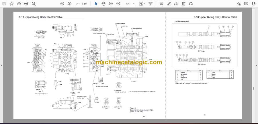
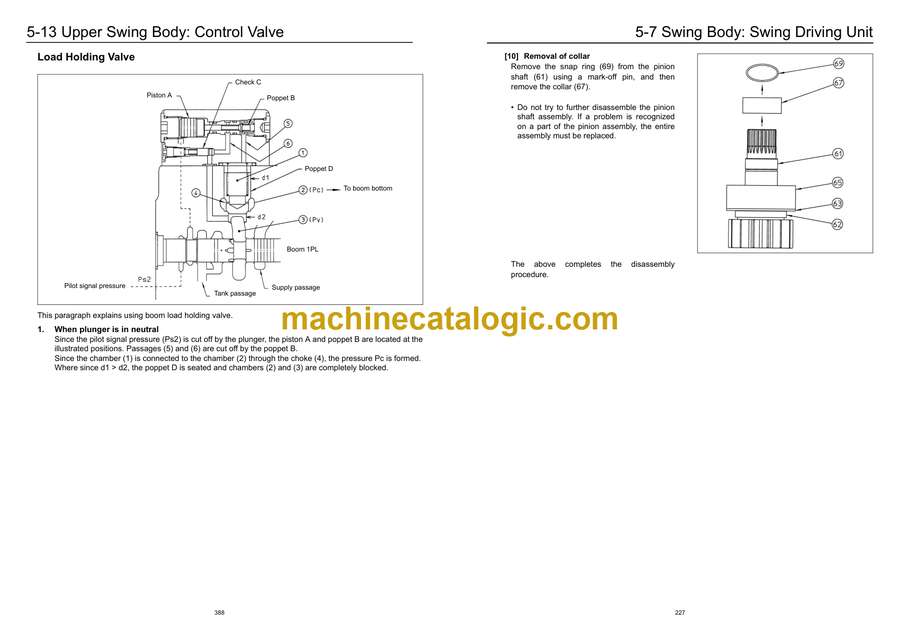
5-13 Upper: Control Valve
1 Assembly and Disassembly of Control Valve ……………………………………………358
5-14 Upper: Solenoid Valve
1 Removal and Installation of 5-Stack Solenoid Valve ………………………………….420
2 Removal and Installation of Cushion Valve ………………………………………………423
3 Assembly and Disassembly of Cushion Valve…………………………………………..426
5-16 Upper: Tank
1 Removal and Installation of Hydraulic Oil Tank …………………………………………435
2 Removal and Installation of Fuel Tank……………………………………………………..442
5-17 Attachment
1 Removal and Installation of Bucket………………………………………………………….447
2 Removal and Installation of Bucket Linkage……………………………………………..449
3 Installation of Bucket Cylinder…………………………………………………………………452
4 Removal and Installation of Arm ……………………………………………………………..455
5 Removal and Installation of Arm Cylinder…………………………………………………457
6 Removal and Installation of Boom…………………………………………………………..461
7 Removal and Installation of Boom Cylinder ………………………………………………466
8 Removal and Installation of Arm HBCV ……………………………………………………470
9 Removal and Installation of Boom HBCV …………………………………………………472
Contents
5-18 Light
1 Removal and Installation of Boom Light………………………………………………….. 475
2 Removal and Installation of Tool Box Light……………………………………………… 476
5-20 Procedures for Removal and Installation of Cab Inner and Outer Parts
1 Removal and Installation of Cab Assembly……………………………………………… 477
2 Removal and Installation of Operator’s Seat……………………………………………. 484
3 Removal and Installation of Wiper …………………………………………………………. 486
4-1Removal and Installation of Wiper Controller…………………………………………… 487
4-2Removal and Installation of Wiper Motor ………………………………………………… 490
5 Removal and Installation of Monitor……………………………………………………….. 493
6 Removal and Installation of Cab Front Glass…………………………………………… 494
7 Adjustment Procedure of Window Lock ………………………………………………….. 496
5-21 Hydraulic Equipment
1 Accumulator ……………………………………………………………………………………….. 498
2 Suction Filter ………………………………………………………………………………………. 499
3 Return Filter ……………………………………………………………………………………….. 501
4 Pilot Filter …………………………………………………………………………………………… 503
5-23 Others
1 Removal and Installation of Side Door……………………………………………………. 504
2 Draining Oil from Hydraulic Oil Tank………………………………………………………. 505


