Komatsu PW148-8, PW160-8, PW180-7plus, PW200-7plus Hydraulic Excavator Operation and Maintenance Manual (VENAM61002)
These wheeled Komatsu PW excavators usually live on roadwork, utility trenches, and urban jobs where you’re constantly moving between sites. This Operation and Maintenance Manual is what I keep handy to set a sane service rhythm and avoid surprise downtime. When a boom function starts to feel sluggish or a travel warning light pops up, I use this book to walk through basic checks, verify the daily and weekly inspections, and decide if it’s something we can sort on-site or if it needs shop time.
Applications & Use Cases
- Plan preventive maintenance so filters, oils, and wear items get attention before they cause breakdowns.
- Build a daily/weekly inspection routine for the undercarriage, tires, boom, and attachments to catch leaks and cracks early.
- Trace hydraulic or control issues by following the recommended checks instead of guessing at the fault.
- Verify correct operating practices for working on pavement, in tight streets, or around traffic so the machine stays stable.
- Coordinate parts and shop work by matching symptoms to likely service needs before you order or schedule.
FAQ
Q: Can I keep this manual on a tablet in the cab?
A: Yes, it works well digitally; you can zoom diagrams and search terms when you’re troubleshooting on-site.
Q: Is it worth printing any pages?
A: I’d print the inspection and service-interval pages and keep them in a binder for quick reference and notes.
Safety Note
Always follow the manual’s lockout, support, and pressure-release steps before inspecting or working on any system.
📘 Show Index
Komatsu PW148-8, PW160-8, PW180-7plus, PW200-7plus Hydraulic Excavator Index:
- VENAM61002 PW148-8/PW160-8/PW180-7 Plus/PW200-7 Plus EN
- 1. Foreword
- 1.1 Foreword
- 1.2 Safety information
- 1.2.1 Signal words
- 1.2.2 Safety labels
- 1.2.3 Emergency steering
- 1.2.4 Emergency braking
- 1.3 Introduction
- 1.3.1 Use of machine
- 1.3.2 Intended use
- 1.3.3 Directions of machine
- 1.3.4 Running in your new machine
- 1.4 Necessary information
- 1.4.1 Product Identification Number (PIN)/Machine serial no. plate and position
- 1.4.2 Engine serial no. plate and position
- 1.4.3 Position of service meter
- 1.4.4 Table to enter serial no. and dealer
- 1.5 Declaration of conformity
- 1.6 Noise
- 1.6.1 Noise emission levels
- 1.6.2 Vibration levels
- 1.7 Contents
- 2. Safety
- 2.1 Safety labels
- 2.1.1 Location of safety labels
- 2.2 General precautions
- Understanding the machine
- 2.2.1 Precautions before starting operation
- 2.2.2 Preparations for safe operation
- 2.2.3 Fire prevention
- 2.2.4 Precautions when getting on or off machine
- 2.2.5 Rotating beacon
- 2.2.6 Electromagnetic interference
- 2.2.7 Do not get caught in articulated portion
- 2.2.8 Precautions related to protective structures
- 2.2.9 Precautions against falling, flying, or intruding objects
- 2.2.10 Unauthorized modification
- 2.2.11 Precautions related to attachments and options
- 2.2.12 Precautions related to cab glass
- 2.2.13 Precautions when running engine inside building
- 2.3 Precautions for operation
- 2.3.1 Precautions for jobsite
- 2.3.2 Starting engine
- 2.3.3 Operation
- 2.3.4 Transportation
- 2.3.5 Towing
- 2.3.6 Bucket with hook or bucket link with lifting eye
- 2.3.7 Handling of fluids
- 2.4 Precautions for maintenance
- 2.4.1 Precautions before starting
- 2.4.2 Precautions for inspection and maintenance
- 2.4.3 Tyres
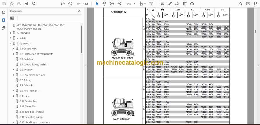
- 2.5 Lifting capacity charts
- 2.5.1 Lifting capacity chart PW148-8
- 2.5.2 Lifting capacity chart PW160-8
- 2.5.3 Lifting capacity chart PW180-7 Plus
- 2.5.4 Lifting capacity chart PW200-7 Plus
- 2.6 Overload caution
- 2.6.1 Overload caution
- 2.6.2 One piece boom – Overload caution PW148-8
- 2.6.3 Two piece boom – Overload caution PW148-8
- 2.6.4 One piece boom – Overload caution PW160-8
- 2.6.5 Two piece boom – Overload caution PW160-8
- 2.6.6 One piece boom – Overload caution PW180-7 Plus
- 2.6.7 Two piece boom – Overload caution PW180-7 Plus
- 2.6.8 Overload caution PW200-7 Plus
- 3. Operation
- 3.1 General view
- 3.1.1 General view of machine
- 3.1.2 General view of controls and gauges
- 3.1.3 General view of Monitor
- 3.2 Explanation of components
- 3.2.1 Machine monitor
- 3.2.2 Basic operation of machine monitor
- 3.2.3 Basic check items
- 3.2.4 Monitor switches
- 3.3 Switches
- 3.4 Control levers, pedals
- 3.5 Window
- 3.5.1 Ceiling window
- 3.5.2 Front window
- 3.5.3 Emergency escape hammer
- 3.5.4 Door lock
- 3.6 Cap, cover with lock
- 3.6.1 Opening and closing cap with lock
- 3.6.2 Opening and closing cover with lock
- 3.6.3 Drink box
- 3.6.4 Magazine box
- 3.7 Ashtray
- 3.8 Cab radio
- 3.9 Air conditioner
- 3.9.1 Air conditioner control panel
- 3.9.2 Method of operation
- 3.9.3 Precautions when using air conditioner
- 3.9.4 Check, maintain machine equipped with air conditioner
- 3.9.5 Auxiliary electric power
- 3.10 Fuse
- 3.11 Fusible link
- 3.12 Controller
- 3.13 Tool box (chassis)
- 3.14 Refuelling pump
- 3.15 Handling accumulators
- 3.15.1 Control circuit accumulator (A)
- 3.15.2 Clutch control accumulator (B)
- 3.15.3 Brake circuit accumulators (C) × 3
- 3.15.4 Brake circuit accumulators (C) × 4
- 3.16 Operation
- 3.16.1 Check before starting engine
- 3.16.2 Check before starting
- 3.16.3 Adjustment of operator’s seat (air suspension seat)
- 3.16.4 Adjustment of operator’s seat (mechanical seat)
- 3.16.5 Seat belt
- 3.16.6 Rear view mirrors
- 3.16.7 Adjusting angle of rear view camera
- 3.16.8 Operations and checks before starting engine
- 3.16.9 Starting engine
- 3.16.10 Ambient temperature range for operation and storage
- 3.16.11 Stopping the engine
- 3.16.12 Machine operation
- 3.16.13 Steering
- 3.16.14 Travelling on public highway
- 3.16.15 Travelling with autocruise
- 3.16.16 Stopping and parking
- 3.16.17 Swinging
- 3.16.18 Operation of work equipment
- 3.16.19 Working mode selection
- 3.16.20 Prohibitions for operation
- 3.16.21 Precautions for operation
- 3.16.22 Recommendations for travelling
- 3.16.23 Precautions when travelling up or down hills
- 3.16.24 How to escape from mud
- 3.16.25 Recommended applications
- 3.16.26 Replacement and inversion of bucket
- 3.16.27 Parking machine
- 3.16.28 Check after stopping engine
- 3.16.29 Machine inspection after daily work
- 3.17 Transportation
- 3.17.1 Transportation procedure
- 3.17.2 Loading, unloading work
- 3.17.3 Securing machine
- 3.17.4 Unloading
- 3.17.5 Lifting the machine
- 3.17.6 Precautions for transportation
- 3.17.7 Travelling posture
- 3.18 Cold weather operation
- 3.18.1 Precautions for low temperature
- 3.18.2 Precautions after completion of work
- 3.18.3 After cold weather
- 3.19 Long-term storage
- 3.19.1 Before storage
- 3.19.2 During storage
- 3.19.3 After storage
- 3.19.4 Starting machine after long-term storage
- 3.20 Troubleshooting
- 3.20.1 Running out of fuel
- 3.20.2 Phenomena that are not failures
- 3.21 Method of towing machine
- 3.22 Precautions on particular jobsites
- 3.23 Discharged battery
- 3.23.1 Removal and installation of battery
- 3.23.2 Battery charges
- 3.23.3 Starting engine with booster cables
- 3.24 Other trouble
- 3.24.1 Electrical system
- 3.24.2 Chassis
- 3.24.3 Engine
- 3.24.4 Electronic control system
- 3.24.5 Point of contact to telephone when error occurs
- 4. Maintenance
- 4.1 Guides to maintenance
- 4.2 Outline of service
- Handling oil, fuel, coolant and performing oil clinic
- Fuel
- Coolant
- Grease
- Carrying out KOWA (KOMATSU Oil Wear Analysis)
- KOWA analysis items
- Oil sampling
- Storing oil and fuel
- Filters
- 4.2.1 Outline of electric system
- 4.2.2 Outline of hydraulic system
- 4.3 Wear parts list
- 4.4 Recommended fuel, coolant and lubricant
- 4.4.1 Proper selection of fuel, coolant and lubricants
- 4.5 Recommended brands, recommended quality for products other than KOMATSU genuine oil
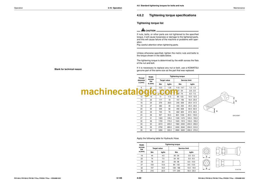
- 4.6 Standard tightening torques for bolts and nuts
- 4.6.1 Introduction of necessary tools
- 4.6.2 Tightening torque specifications
- 4.7 Periodic replacement of safety critical parts
- 4.7.1 Safety critical parts
- 4.8 Maintenance schedule chart
- 4.9 Explanation of lubrication chart decals
- Lubrication points PW148-8
- Lubrication points PW160-8
- Lubrication points PW180-7 Plus
- Lubrication points PW200-7 Plus
- 4.10 Maintenance interval for hydraulic breaker
- 4.11 Maintenance procedure
- 4.11.1 Initial 50 hours maintenance (only after the first 50 hours)
- 4.11.2 Initial 250 hours maintenance (only after the first 250 hours)
- 4.11.3 Initial 500 hours maintenance (only after the first 500 hours)
- 4.11.4 Initial 1000 hours maintenance (only after the first 1000 hours)
- 4.11.5 When required
- 4.11.6 Check before starting
- 4.11.7 Every 100 hours maintenance
- 4.11.8 Every 250 hours maintenance
- 4.11.9 Every 500 hours maintenance
- 4.11.10 Every 1000 hours maintenance
- 4.11.11 Every 2000 hours maintenance
- 4.11.12 Every 4000 hours maintenance
- 4.11.13 Every 5000 hours maintenance
- 4.11.14 Every 8000 hours maintenance
- 5. Technical Data
- 5.1 Specifications
- Operating weight
- 5.1.1 Dimensions
- 5.1.2 Working range – One piece boom
- 5.1.3 Working range – Two piece boom
- 5.1.4 Working range – Rotating arm
- 6. Attachments and Options
- 6.1 General precautions for safety
- 6.1.1 Precautions when selecting
- 6.1.2 Read the instruction manual thoroughly
- 6.1.3 Precautions when removing or installing
- 6.1.4 Precautions when using
- 6.2 Hydraulic quick coupler piping
- 6.2.1 Locations
- 6.2.2 Operation
- 6.3 Handling bucket with hook
- 6.3.1 Checking for damage to bucket with hook
- 6.3.2 Prohibited operations
- 6.3.3 Precautions during operations
- 6.4 Machines ready for attachments
- 6.4.1 Clamshell operation selector valves
- 6.4.2 Handling the clamshell bucket
- 6.4.3 Hydraulic circuit
- 6.4.4 Attachment operations
- 6.4.5 Attachment flow settings
- 6.4.6 Method for releasing pressure in control circuit of machines equipped with accumulator
- 6.4.7 Long-term storage
- 6.4.8 Specifications
- 6.5 Introduction of attachments and extending machine service life
- 6.5.1 Hydraulic breaker
- 6.5.2 Power ripper
- 6.5.3 Fork grab
- 6.5.4 Grapple bucket
- 6.5.5 Scrap grapple
- 6.5.6 Crusher and smasher
- 6.5.7 Hydraulic pile driver
- 6.5.8 Hydraulic excavator with multipurpose crane
- 6.6 Rotating arm
- 6.6.1 General location and specifications.
- 6.6.2 Maintenance requirement
- 6.7 Attachment guide
- Upper boom control pedal (two piece boom)
- 6.7.1 Excavator’s work
- 6.7.2 Replacement of bucket
- 6.7.3 Trapezoidal bucket
- 6.8 Handling machines equipped with KOMTRAX
- 6.9 Central lubrication system
- 6.9.1 Changing the lubrication interval times
- 6.9.2 Operating the central lubrication system
- 6.9.3 Display and control unit
- 6.10 Cleanfix fan
- 6.11 Undercarriage auxiliary hydraulic circuit
- 7. Index
- 8. Notes
Link Belt


