$ 0
0
$ 0
0

Hyster H80FT, H90FT, H100FT, H110FT, H120FT (N005 F813) Forklift Service Manual

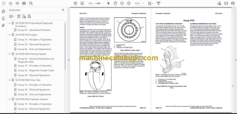
Format: PDF (Printable Document)

File Language: English

File Pages (Total): 12088

File Size (Total): 508.12 MB (Speed Download Link)

Brand: Hyster

Model: H80-H90-H100-H110-H120FT (U005 K813) Forklift

Type of Document: Service Manual

Categories: ,

$ 45

Share:

Hyster H80FT, H90FT, H100FT, H110FT, H120FT (N005 F813) Forklift Service Manual

Hyster H80FT, H90FT, H100FT, H110FT, H120FT (N005 F813) Forklift Service Manual

📘 Show Index

Hyster H80FT, H90FT, H100FT, H110FT, H120FT (N005 F813) Forklift Index:

  • SECTION 9010 Operational Diagnostic Procedures
    • Group 05 – Operational Checkout
  • SECTION 9020 Engine
    • Group 10 – Principles of Operation
    • Group 30 – Observed Symptoms
    • Group 40 – Tests and Adjustments
  • SECTION 9030 Electrical System
    • Group 03 – General Maintenance and Diagnostic Data
    • Group 10 – Principles of Operation
    • Group 20 – Diagnostic Trouble Codes
    • Group 30 – Observed Symptoms
  • SECTION 9040 Drive Train
    • Group 10 – Principles of Operation
    • Group 30 – Observed Symptoms
    • Group 40 – Tests and Adjustments
  • SECTION 9050 Hydraulic Systems
    • Group 10 – Principles of Operation
    • Group 30 – Observed Symptoms
    • Group 33 – Observed Symptoms-Gear Pump
    • Group 35 – Observed Symptoms-Variable Displacement Pump (VDP)
    • Group 40 – Tests and Adjustments
    • Group 43 – Tests and Adjustments-Gear Pump
    • Group 45 – Tests and Adjustments-Variable Displacement Pump (VDP)
  • SECTION 9060 Operators Station
    • Group 10 – Principles of Operation
  • SECTION 9070 Front End (Mast) and Chassis
    • Group 10 – Principles of Operation
    • Group 30 – Observed Symptoms
  • SECTION 9080 Supplementary Data
    • Group 50 – Abbreviations and Acronyms
    • Group 60 – Special Tools List
    • Group 70 – Fault Mode Indicator Reference
    • Group 80 – Supplier Specification Data
  • General
    • Identification Plate
  • Drive Axle Removal
  • Hub Seal Replacement
  • Planetary Reduction Repair
    • Clean and Inspect
  • Brake Repair
    • Clean and Inspect
      • Wet Brake Noise Reduction
  • Bevel Pinion
    • Clean and Inspect
  • Differential Unit
    • Disassemble
    • Clean and Inspect
    • Assemble
  • Drive Axle Installation
  • Special Tools
  • Torque Specifications
  • General
  • Display Switch Cluster
    • Remove
    • Install
    • Direction Control and Turn Signal Levers
      • Remove
      • Install
    • Key Switch
      • Remove
      • Install
    • Display Switch Cluster Panel Bezel and Overlay
      • Remove
      • Install
  • Steering Column Repair
    • Remove
    • Disassemble
    • Assemble
    • Install
  • Sensors and Switches
    • General
      • Dash and Kick Panel, Remove and Install
    • Accelerator Pedal Position Sensor
      • Remove
      • Install
    • Brake Fluid Level Switch
      • Remove
      • Install
    • Service Brake Pedal Position Sensor
      • Remove
      • Install
    • Parking Brake Sensor
      • Remove
      • Install
    • Service Brake Pressure Sensor
      • Remove
      • Install
    • Accumulator Pressure Switch For Lift Truck Models H8.0FT, H8.0FT9, H9.0FT (H170FT, H175FT36, H190FT) (A299, B299)
      • Remove
      • Install
    • Sensor Microswitch (MONOTROL® Pedal)
      • Remove
      • Install
    • Low Coolant Level Sensor
      • Remove
      • Install
    • Fuel Level Sensor, Gas and Diesel Engines Only
      • Remove
      • Install
    • Armrest Switch
      • Remove
      • Install
    • Seat Sensor (Operator Presence System)
      • Non-Suspension and Semi-Suspension Seats; For Lift truck Models S30-35FT, S40FTS (E010), H1.6-1.8FT, H2.0FTS (H30-35FT, H40FTS) (F001), S2.0-3.5FT (S40-70FT, S55FTS) (F187), H2.0-3.5FT (H40-70FT) (L177), S4.0-5.5FT, S5.5FTS (S80-120FT; S80-100FTBCS; S120FTS; S120FTPRS) (G004, H004), H4.0FT5/FT6; H4.5FTS5, H4.5FT6, H5.0-5.5FT (H80-120FT) (N005, P005, R005, S005), and S6.0-7.0FT (S135-155FT) (D024, E024, F024, G024)
      • Non-Suspension Seats; Lift Truck Models H6.0FT, H7.0FT (H135FT, H155FT) (H006, J006, K006)
      • Full Suspension Seats; All Lift Truck Models
    • Hood Shut Off Switch
      • Remove
      • Install
    • Remote Key Switch
      • Remove
      • Install
    • Hydraulic Filter Pressure Switch
      • Remove
      • Install
    • Transmission Speed Sensor
      • Remove
      • Install
    • Transmission Pressure Sensors
      • Remove
      • Install
    • Transmission Temperature Sensor
      • Remove
      • Install
    • Engine Speed Sensor
      • Remove
      • Install
    • Intermediate Speed Sensor
      • Remove
      • Install
    • Return to Set Tilt (Tilt Angle) Sensor
      • Lift Truck Models S30FT, S35FT, S40FTS (E010); H1.6FT, H1.8FT, H2.0FTS (H30FT, H35FT, H40FTS) (F001); S2.0-3.5FT (S40-70FT, S55FTS) (F187); H2.0-3.5FT (H40-70FT) (L177)
      • Lift Truck Models S6.0FT, S7.0FT (S135FT, S155FT) (D024, E024, F024, G024); S4.0, 5.0, 5.5FT, S5.5FTS (S80, 100, 120FT; S80, 100FTBCS; S120FTS; S120FTPRS) (G004, H004), H4.0FT5/FT6; H4.5FTS5, H4.5FT6; H5.0-5.5FT (H80, 90, 100, 110, 120FT) (N005, P005, R005, S005), H6.0FT, H7.0FT (H135FT, H155FT) (H006, J006, K006), H8.0FT, H8.0FT9, H9.0FT (H170FT, H175FT36, H190FT) (A299, B299)
    • Rear Horn Button Switch
      • Remove
      • Install
    • Impact Sensor
      • Lift Truck Models S30FT-35FT, S40FTS (E010), H1.6-1.8FT, H2.0FTS (H30-35FT, H40FTS) (F001), S2.0-3.5FT (S40-70FT, S55FTS) (F187), H2.0-3.5FT (H40-70FT) (L177), S4.0-5.5FT, S5.5FTS (S80-120FT; S80-100FTBCS; S120FTS; S120FTPRS) (G004, H004), H4.0FT5/FT6; H4.5FTS5, H4.5FT6, H5.0-5.5FT (H80-120FT) (N005, P005, R005, S005), and S6.0-7.0FT (S135-155FT) (D024, E024, F024, G024)
      • Lift Truck Models H6.0FT, H7.0FT (H135FT, H155FT) (H006, J006, K006), H8.0FT, H8.0FT9, H9.0FT (H170FT, H175FT36, H190FT) (A299, B299)
    • Load Weight Sensor
      • Remove
      • Install
    • Engine and Fuel Sensors and Switches, Gas and LPG Trucks Equipped with Mazda Engines2.0L and 2.2L
    • Engine and Fuel Sensors and Switches, Gas and LPG Trucks Equipped with GM Engines
      • Crankshaft Position (CKP) Sensor
      • Camshaft Position (CMP) Sensor
      • Oil Pressure Sensor
      • Manifold Absolute Pressure (MAP)/Manifold Air Temperature (MAT) Sensor
      • Engine Coolant Temperature (ECT) Sensor
      • Air Flow Restriction Switch
      • Oxygen Sensor
    • Engine and Fuel Sensors and Switches, PSI 4.3L LPG Engine
      • Crankshaft Position (CKP) Sensor
      • Camshaft Position (CMP) Sensor
      • Oil Pressure Sensor
      • Manifold Absolute Pressure (MAP)/Manifold Air Temperature (MAT) Sensor
      • Engine Coolant Temperature (ECT) Sensor
      • Air Flow Restriction Switch
      • Oxygen Sensor
    • Engine and Fuel Switches, GM 2.4L LPG Trucks Only
      • Low LPG Pressure Switch
    • Engine and Fuel Sensors and Switches, Yanmar Diesel Trucks
      • Air Filter Restriction Switch
      • Oil Pressure Sensor
      • Engine Speed Sensor
      • Engine Coolant Temperature (ECT) Sensor
      • Throttle Position Sensor (TPS)
      • Fuel/Water Separator Sensor
      • Glow Plug Relay
    • Engine and Fuel Sensors and Switches, Cummins Diesel Engines
      • Air Filter Restriction Switch
      • Engine Oil Pressure Sensor
      • Engine Speed Sensor
      • Engine Coolant Temperature (ECT) Sensor
      • Throttle Position Sensor (TPS) (Cummins 4.5L Only)
      • Fuel/Water Separator Sensor
    • Engine and Fuel Sensors and Switches, Kubota 3.8L Diesel Engine Without DPF
      • Intake Air Temperature Sensor
      • Intake Air Pressure Sensor
      • Air Inlet Heater
      • Engine Oil Pressure Sensor
      • Engine Coolant Temperature (ECT) Sensor
      • Crankshaft Position Sensor
      • Camshaft Position Sensor
      • Air Flow Restriction Sensor
      • Fuel/Water Separator
    • Engine and Fuel Sensors and Switches, Kubota 3.8L Diesel Engine With DPF
      • Intake Air Temperature Sensor
      • Boost Sensor
      • Throttle Valve Assembly and Air Intake Heater
      • Engine Coolant Temperature (ECT) Sensor
      • Engine Oil Pressure Sensor
      • Crankshaft Position Sensor
      • Camshaft Position Sensor
      • Differential Pressure Sensor
      • Mass Air Flow Sensor
      • Fuel/Water Separator
    • Engine and Fuel Sensors and Switches, Kubota 3.6L Diesel Engine
      • Engine Coolant Temperature (ECT) Sensor
      • Throttle Position Sensor
      • Engine Oil Pressure Sensor
      • Engine Speed Sensor
      • Fuel Shut Off Solenoid
  • Vehicle System Manager (VSM)
    • General
    • VSM Replacement
      • Remove
      • Install
    • Programming a New VSM and/or Display Switch Cluster
      • General
      • PC Service Tool Software
      • Data Transferring
  • Power Distribution Module (PDM) and Component Parts
    • Remove
      • PDM as a Unit
    • Install
      • PDM as a Unit
    • Remove and Install
      • PDM Component Parts
  • Transmission Control Unit
    • Remove
    • Install
  • Battery
    • Remove
    • Install
  • Lights
    • Work Lights (Front and Rear)
      • Remove
      • Install
    • Strobe Light
      • Remove
      • Install
    • LED Tail, Backup, and Brake Lights
      • Remove
      • Install
    • Front Marker/Turn Signal Lights
      • Replacing Whole Front Marker/Turn Signal Light Assembly
      • Replacing Just the Front Marker/Turn Signal Light LED Light Lens
  • Diesel Particulate Filter (DPF) Display
    • Remove
    • Clean and Inspect
    • Install
  • Electronic-Hydraulic Controls – Generation 1
    • E-Hydraulic Controls – Test
      • Mini-Levers
      • Full Stroke Test
      • Function Returns to Neutral Test
      • Push Button Switch
    • General
    • Mini-Lever Replacement
      • Remove
      • Clean and Inspect
      • Install
    • Push Button Switch Replacement
      • Remove
      • Install
    • Mini-Lever Module (MLM)
      • Remove
      • Install
    • Joystick
      • Remove and Disassemble
      • Inspect
      • Assemble and Install
  • Electronic-Hydraulic Controls – Generation 2, Before January, 2020
    • General
    • Mini-levers, Remove and Install
    • Armrest Assembly
      • Remove
      • Install
    • Horn Button
      • Remove
      • Install
    • Direction Control Switch
      • Remove
      • Install
    • push (override) buttons and Toggle Switch
      • Remove
      • Install
    • Joystick
      • Remove and Disassemble
      • Inspect
      • Assemble and Install
    • Joystick Armrest Slider Assembly
      • Remove
      • Install
  • Electronic-Hydraulic Controls, After January, 2020
    • E-Hydraulic Controls – TEST
      • Mini-Levers
      • Full Stroke Test
      • Function Returns to Neutral Test
      • Push (Override) Button
    • General
    • Mini-levers, Remove and Install
    • Armrest Assembly
      • Remove
      • Install
    • Horn Button
      • Remove
      • Install
    • Direction Control Switch
      • Remove
      • Install
      • Push (Override) buttons and Toggle Switch
  • Special Tools

Hyster

Latest Product

0
    0
    Your Cart
    Your cart is emptyReturn to Shop