Format: PDF (Printable Document)
File Language: English
File Pages: 2168
File Size: 180.74 MB (Speed Download Link)
Brand: Hyster
Model: N30XMXDR, N45XMXR (A264 A861) Forklift
Type of Document: Service Manual
$ 45
General …………………………………………………………………………………………………………………………………………….. 1
Component Repair and Testing – General ……………………………………………………………………………………………. 2
Contactor Panel Assembly………………………………………………………………………………………………………………….. 2
Description/Features ……………………………………………………………………………………………………………………… 2
Remove …………………………………………………………………………………………………………………………………………. 2
Install …………………………………………………………………………………………………………………………………………… 3
Contactors ………………………………………………………………………………………………………………………………………… 3
Description/Features ……………………………………………………………………………………………………………………… 3
Auxiliary Switch ……………………………………………………………………………………………………………………………. 4
Testing ………………………………………………………………………………………………………………………………………….. 4
Remove …………………………………………………………………………………………………………………………………………. 5
Install …………………………………………………………………………………………………………………………………………… 5
EE Contactors ……………………………………………………………………………………………………………………………….. 5
Fuses………………………………………………………………………………………………………………………………………………… 7
Relays ………………………………………………………………………………………………………………………………………………. 8
Description/Features ……………………………………………………………………………………………………………………… 8
Enable Relay …………………………………………………………………………………………………………………………………. 8
Hourmeter Relay …………………………………………………………………………………………………………………………… 8
Lift/Lower Relay (Trucks Built After 1 August 2002) ……………………………………………………………………….. 8
Coil Testing …………………………………………………………………………………………………………………………………… 8
Contact Testing……………………………………………………………………………………………………………………………… 9
Remove and Install………………………………………………………………………………………………………………………… 9
Height Proximity Switch ………………………………………………………………………………………………………………….. 10
Remove ……………………………………………………………………………………………………………………………………….. 10
Test …………………………………………………………………………………………………………………………………………….. 10
Install …………………………………………………………………………………………………………………………………………. 11
Adjust …………………………………………………………………………………………………………………………………………. 11
Key Switch………………………………………………………………………………………………………………………………………. 11
Description………………………………………………………………………………………………………………………………….. 11
Remove ……………………………………………………………………………………………………………………………………….. 11
Install …………………………………………………………………………………………………………………………………………. 12
Battery Disconnect Switch ……………………………………………………………………………………………………………….. 12
Description………………………………………………………………………………………………………………………………….. 12
Remove ……………………………………………………………………………………………………………………………………….. 12
Install …………………………………………………………………………………………………………………………………………. 12
Proportional Electro-Hydraulic Control Valves ………………………………………………………………………………….. 13
Manual Lowering…………………………………………………………………………………………………………………………. 13
Trucks Built Before 1 August, 2002 …………………………………………………………………………………………… 13
Trucks Built After 1 August, 2002 …………………………………………………………………………………………….. 14
Operation ……………………………………………………………………………………………………………………………………. 14
Repair …………………………………………………………………………………………………………………………………………. 14
Carriage Valve Assembly and Selector Valves …………………………………………………………………………………… 15
Test/Remove/Install ……………………………………………………………………………………………………………………… 15
Multifunction Control Handle…………………………………………………………………………………………………………… 16
Description/Features ……………………………………………………………………………………………………………………. 16
Remove ……………………………………………………………………………………………………………………………………….. 16
Disassemble ………………………………………………………………………………………………………………………………… 17
Tools Required …………………………………………………………………………………………………………………………. 17
Assemble …………………………………………………………………………………………………………………………………….. 19
Install …………………………………………………………………………………………………………………………………………. 20
Shelf Height Selector ……………………………………………………………………………………………………………………….. 20
©2005 HYSTER COMPANY i
Table of Contents Electrical System
TABLE OF CONTENTS (Continued)
Description/Features ……………………………………………………………………………………………………………………. 20
Shelf Height Selector ……………………………………………………………………………………………………………….. 20
Power On, Start Up………………………………………………………………………………………………………………….. 20
Programming ………………………………………………………………………………………………………………………………. 21
Field Program Mode…………………………………………………………………………………………………………………. 21
Enter Shelf Level……………………………………………………………………………………………………………………… 21
Set Shelf Level…………………………………………………………………………………………………………………………. 21
Quick Pick Level Keys ……………………………………………………………………………………………………………… 21
Set Minimum Lift Speed…………………………………………………………………………………………………………… 21
Set Minimum Lower Speed……………………………………………………………………………………………………….. 22
Changing the 3-Digit Security Code…………………………………………………………………………………………… 22
Factory Program Mode……………………………………………………………………………………………………………… 22
Calibrate Lift …………………………………………………………………………………………………………………………… 22
Set Options ……………………………………………………………………………………………………………………………… 22
Control Zone ……………………………………………………………………………………………………………………………. 23
Deadband………………………………………………………………………………………………………………………………… 23
Reset User Code ………………………………………………………………………………………………………………………. 23
Clear All ………………………………………………………………………………………………………………………………….. 23
Show All Levels ……………………………………………………………………………………………………………………….. 24
Set LCD Bias …………………………………………………………………………………………………………………………… 24
Show Analog ……………………………………………………………………………………………………………………………. 24
External Inputs ……………………………………………………………………………………………………………………….. 24
System Errors ……………………………………………………………………………………………………………………………… 24
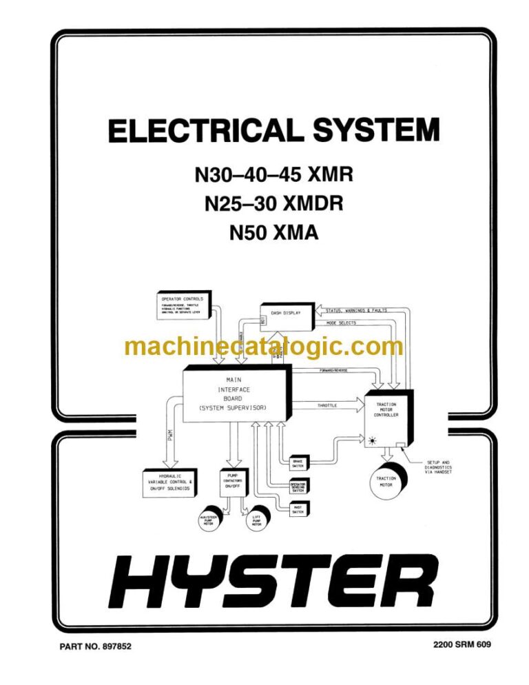
Main Interface Board (MIB) Adjustments ……………………………………………………………………………………… 24
Function 32 Hydraulic Potentiometer – Set-Up…………………………………………………………………………… 25
Function 02 Lift Minimum Rate………………………………………………………………………………………………… 25
Function 04 Lower Minimum Rate ……………………………………………………………………………………………. 25
Function 59 Hydraulic Lift Function – Stopping Rate …………………………………………………………………. 25
Function 61 Hydraulic Lower Function – Stopping Rate ……………………………………………………………… 25
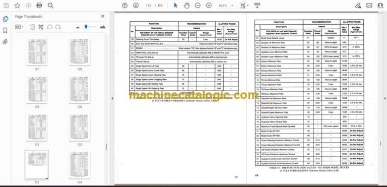
Main Interface Board (MIB)……………………………………………………………………………………………………………… 25
Description/Features ……………………………………………………………………………………………………………………. 25
Operation ……………………………………………………………………………………………………………………………………. 26
LED Display………………………………………………………………………………………………………………………………… 26
MIB, Remove……………………………………………………………………………………………………………………………….. 27
MIB J-Connector, Repair………………………………………………………………………………………………………………. 28
Inspect…………………………………………………………………………………………………………………………………….. 28
MIB, Install…………………………………………………………………………………………………………………………………. 29
Main Interface Board (MIB) Setup Procedures…………………………………………………………………………………… 29
General……………………………………………………………………………………………………………………………………….. 29
Default Values……………………………………………………………………………………………………………………………… 30
Checking Model Code, Software Version, and Setup Status…………………………………………………………….. 30
MIB Generation II Setup Procedure………………………………………………………………………………………………. 30
Entering the Setup Mode………………………………………………………………………………………………………….. 30
Editing Settings……………………………………………………………………………………………………………………….. 30
Changing the Setting Values …………………………………………………………………………………………………….. 30
Entering Text…………………………………………………………………………………………………………………………… 30
System Information and Fault Log ……………………………………………………………………………………………. 30
Passwords ……………………………………………………………………………………………………………………………….. 31
Defaults…………………………………………………………………………………………………………………………………… 31
Exit and Save…………………………………………………………………………………………………………………………… 31
Parameters ……………………………………………………………………………………………………………………………… 31
Top Level Menu Items………………………………………………………………………………………………………………. 32
Options ……………………………………………………………………………………………………………………………….. 32
Handle Deadband ………………………………………………………………………………………………………………… 32
Lift/Lower ……………………………………………………………………………………………………………………………. 32
Speeds…………………………………………………………………………………………………………………………………. 33
Auxiliary……………………………………………………………………………………………………………………………… 33
Max Speed and Low End Adjustments ………………………………………………………………………………………….. 33
Customizing MIB Functions …………………………………………………………………………………………………………. 34
MIB Status, Warning, and Fault Codes …………………………………………………………………………………………….. 48
General……………………………………………………………………………………………………………………………………….. 48
Troubleshooting Charts………………………………………………………………………………………………………………… 48
Blank or Undefined Code Conditions ………………………………………………………………………………………………… 50
Status Codes……………………………………………………………………………………………………………………………………. 54
Warning Codes ………………………………………………………………………………………………………………………………… 58
Fault Codes …………………………………………………………………………………………………………………………………….. 62
SEM Traction Motor Controller ………………………………………………………………………………………………………… 71
Description/Features ……………………………………………………………………………………………………………………. 71
Remove ……………………………………………………………………………………………………………………………………….. 71
Test …………………………………………………………………………………………………………………………………………….. 72
Install …………………………………………………………………………………………………………………………………………. 72
1307 Programmer Handset ………………………………………………………………………………………………………………. 74
Description/Features ……………………………………………………………………………………………………………………. 74
SCROLL DISPLAY Keys………………………………………………………………………………………………………………. 74
CHANGE VALUE Keys………………………………………………………………………………………………………………… 74
MORE INFO Key…………………………………………………………………………………………………………………………. 74
Operation ……………………………………………………………………………………………………………………………………. 75
Connecting Handset to Traction Motor Controller………………………………………………………………………. 75
Disconnecting Handset from Traction Motor Controller………………………………………………………………. 75
Programmer Self Test ………………………………………………………………………………………………………………. 75
Operating Modes………………………………………………………………………………………………………………………….. 76
Program Menu…………………………………………………………………………………………………………………………. 76
Test Menu ……………………………………………………………………………………………………………………………….. 77
Diagnostics Menu…………………………………………………………………………………………………………………….. 77
Diagnostic History……………………………………………………………………………………………………………………. 78
Special Program Menu……………………………………………………………………………………………………………… 78
Programming the Traction Motor Controller – 1307 Handset ………………………………………………………………. 79
1311 Programmer Handset ………………………………………………………………………………………………………………. 81
Description/Features ……………………………………………………………………………………………………………………. 81
Menu Navigation Key ………………………………………………………………………………………………………………. 82
Data Increase/Decrease Key……………………………………………………………………………………………………… 82
Bookmark Keys ……………………………………………………………………………………………………………………….. 83
Operation ……………………………………………………………………………………………………………………………………. 83
Connecting Handset to Traction Motor Controller………………………………………………………………………. 83
Disconnecting the Handset From the Traction Motor Controller………………………………………………….. 83
Main Menu Selections ………………………………………………………………………………………………………………….. 83
Program Menu…………………………………………………………………………………………………………………………. 83
Monitor Menu………………………………………………………………………………………………………………………….. 84
Faults Menu ……………………………………………………………………………………………………………………………. 84
Functions menu……………………………………………………………………………………………………………………….. 85
Information Menu ……………………………………………………………………………………………………………………. 86
Programmer Setup Menu …………………………………………………………………………………………………………. 86
iii
Table of Contents Electrical System
TABLE OF CONTENTS (Continued)
Programming the Traction Motor Controller – 1311 Handset ………………………………………………………………. 86
Troubleshooting……………………………………………………………………………………………………………………………….. 87
Status LED Diagnostics ……………………………………………………………………………………………………………….. 87
Programmer Diagnostics………………………………………………………………………………………………………………. 88
Diagnostics Menu ………………………………………………………………………………………………………………………… 89
Test Menu……………………………………………………………………………………………………………………………………. 98
Dash Display Assembly ………………………………………………………………………………………………………………….. 101
Description and Features……………………………………………………………………………………………………………. 101
Operation ………………………………………………………………………………………………………………………………….. 102
Battery Indicator……………………………………………………………………………………………………………………. 103
Remove ……………………………………………………………………………………………………………………………………… 103
Install ……………………………………………………………………………………………………………………………………….. 104
Voltage Selection………………………………………………………………………………………………………………………… 104
Dash Display, Adjust ………………………………………………………………………………………………………………….. 104
Battery Indicator Profile Settings ……………………………………………………………………………………………….. 105
Troubleshooting …………………………………………………………………………………………………………………………. 105
Inoperative Dash Display Assembly ………………………………………………………………………………………… 105
Inoperative Drive Mode Selection ……………………………………………………………………………………………. 105
Troubleshooting the Dash Display With a Programmer Handset ……………………………………………….. 105
Troubleshooting Without a Programmer Handset …………………………………………………………………….. 106
No Warnings or Faults Displayed ……………………………………………………………………………………………. 106
Lift Interrupt …………………………………………………………………………………………………………………………. 107
Lost MIB Signal Displayed……………………………………………………………………………………………………… 107
Hourmeter Input ……………………………………………………………………………………………………………………. 107
