$ 0
0
$ 0
0

John Deere 670G, 670GP, 672G, and 672GP Motor Grader Operation and Test Technical Manual (TM14252X19)

Format: PDF (Printable Document)

File Language: English

File Pages: 1542

File Size: 51.18 MB (Speed Download Link)

Brand: John Deere

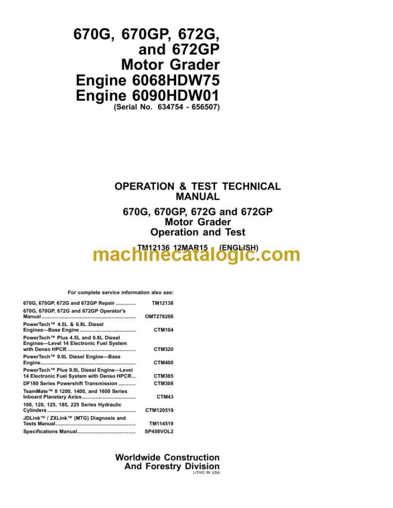
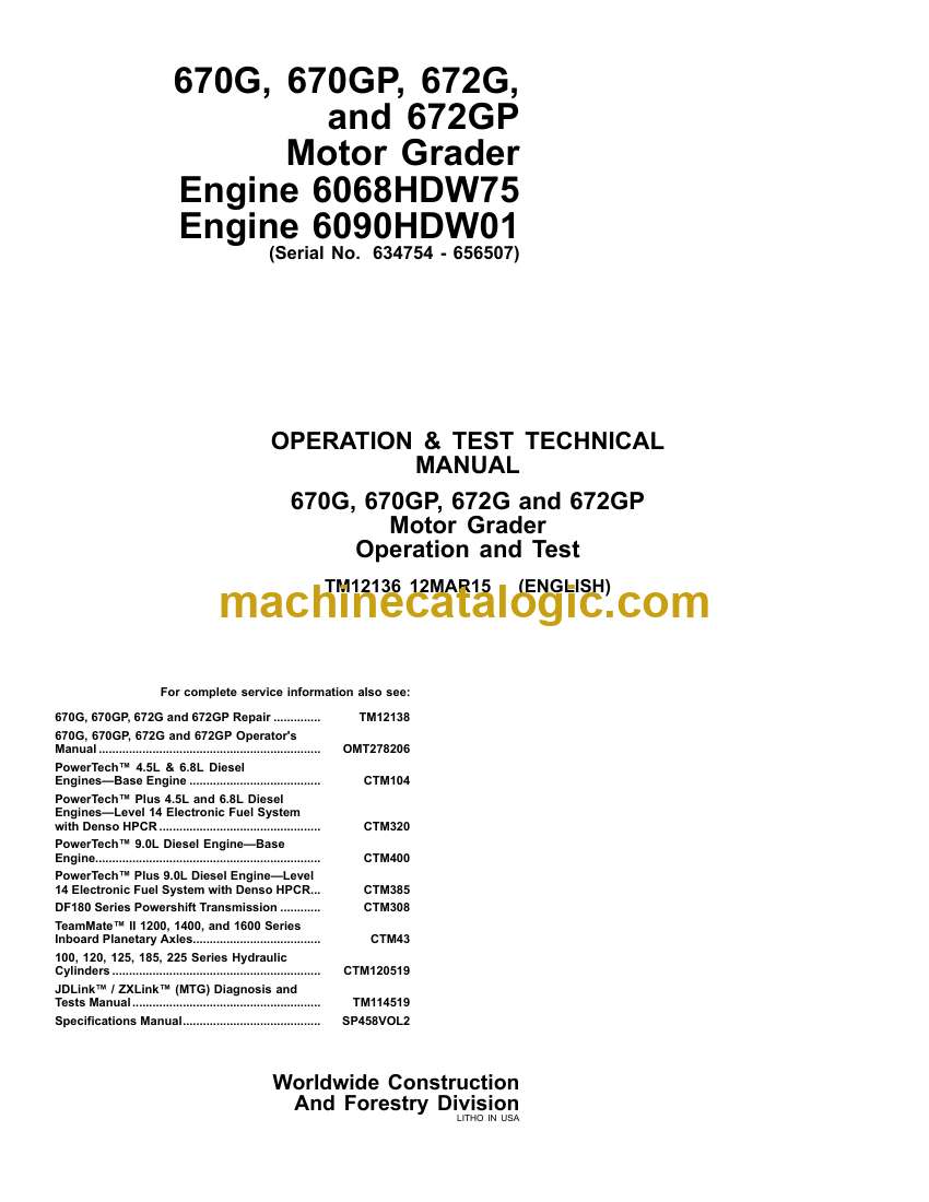
Model: 670G, 670GP, 672G, and 672GP Motor Grader

Book No: TM14252X19

Type of Document: Operation and Test Technical Manual

Categories: ,

$ 40

Share:

John Deere 670G, 670GP, 672G, and 672GP Motor Grader Operation and Test Technical Manual (TM14252X19)

John Deere 670G, 670GP, 672G, and 672GP Motor Grader Operation and Test Technical Manual (TM14252X19)

📘 Show Index

John Deere 670G, 670GP, 672G, and 672GP Motor Grader Index:

  • Contents
    • General Information
      • Safety
        • Recognize Safety Information
        • Follow Safety Instructions
        • Operate Only If Qualified
        • Wear Protective Equipment
        • Avoid Unauthorized Machine Modifications
        • Inspect Machine
        • Stay Clear of Moving Parts
        • Avoid High-Pressure Fluids
        • Avoid High-Pressure Oils
        • Work In Ventilated Area
        • Prevent Fires
        • Prevent Battery Explosions
        • Handle Chemical Products Safely
        • Dispose of Waste Properly
        • Prepare for Emergencies
        • Clean Debris from Machine
        • Use Steps and Handholds Correctly
        • Start Only From Operator’s Seat
        • Use and Maintain Seat Belt
        • Prevent Unintended Machine Movement
        • Avoid Work Site Hazards
        • Keep Riders Off Machine
        • Avoid Backover Accidents
        • Avoid Machine Tip-Over
        • Operating Or Traveling On Public Roads
        • Inspect and Maintain ROPS
        • Add and Operate Attachments Safely
        • Park and Prepare for Service Safely
        • Service Cooling System Safely
        • Remove Paint Before Welding or Heating
        • Make Welding Repairs Safely
        • Drive Metal Pins Safely
        • Service Tires Safely
    • Diagnostics
      • PCU Diagnostic Trouble Codes
        • 000177.00 — Transmission Oil Temperature High
          • Transmission Oil Temperature High Diagnostic Procedure
        • 000177.04 — Transmission Oil Temperature Short To Ground
          • Transmission Oil Temperature Short To Ground Diagnostic Procedure
        • 000525.02 — Program Variable REQ_GEAR Has Taken On An Invalid Value
          • Program Variable REQ_GEAR Has Taken On An Invalid Value Diagnostic Procedure
        • 000525.12 — Request For An Undefined Shift Being Made
          • Request For An Undefined Shift Being Made Diagnostic Procedure
        • 000723.02 — Transmission Input Speed Sensor Bad Data
          • Transmission Input Speed Sensor Bad Data Diagnostic Procedure
        • 002000.02 — ECU CAN Data Invalid
          • ECU CAN Data Invalid Diagnostic Procedure
        • 002000.09 — Can Communication Lost For ECU
          • CAN Communication Lost For ECU Diagnostic Procedure
        • 002033.02 — FLC CAN Data Invalid
          • FLC CAN Data Invalid Diagnostic Procedure
        • 002033.09 — CAN Communication Lost For FLC
          • CAN Communication Lost For FLC Diagnostic Procedure
        • 002225.09 — CAN Communication Lost For Six Wheel Drive
          • CAN Communication Lost For Six Wheel Drive Diagnostic Procedure
        • 522252.00 — Clutch 1 Hold Pressure Too High
          • Clutch 1 Hold Pressure Too High Diagnostic Procedure
        • 522252.01 — Clutch 1 Hold Pressure Too Low
          • Clutch 1 Hold Pressure Too Low Diagnostic Procedure
        • 522253.00 — Clutch 2 Hold Pressure Too High
          • Clutch 2 Hold Pressure Too High Diagnostic Procedure
        • 522253.01 — Clutch 2 Hold Pressure Too Low
          • Clutch 2 Hold Pressure Too Low Diagnostic Procedure
        • 522254.00 — Clutch 3 Hold Pressure Too High
          • Clutch 3 Hold Pressure Too High Diagnostic Procedure
        • 522254.01 — Clutch 3 Hold Pressure Too Low
          • Clutch 3 Hold Pressure Too Low Diagnostic Procedure
        • 522255.00 — Clutch 4 Hold Pressure Too High
          • Clutch 4 Hold Pressure Too High Diagnostic Procedure
        • 522255.01 — Clutch 4 Hold Pressure Too Low
          • Clutch 4 Hold Pressure Too Low Diagnostic Procedure
        • 522256.00 — Clutch A Hold Pressure Too High
          • Clutch A Hold Pressure Too High Diagnostic Procedure
        • 522256.01 — Clutch A Hold Pressure Too Low
          • Clutch A Hold Pressure Too Low Diagnostic Procedure
        • 522257.00 — Clutch B Hold Pressure Too High
          • Clutch B Hold Pressure Too High Diagnostic Procedure
        • 522257.01 — Clutch B Hold Pressure Too Low
          • Clutch B Hold Pressure Too Low Diagnostic Procedure
        • 522258.00 — Clutch C Hold Pressure Too High
          • Clutch C Hold Pressure Too High Diagnostic Procedure
        • 522258.01 — Clutch C Hold Pressure Too Low
          • Clutch C Hold Pressure Too Low Diagnostic Procedure
        • 522259.00 — Clutch D Hold Pressure Too High
          • Clutch D Hold Pressure Too High Diagnostic Procedure
        • 522259.01 — Clutch D Hold Pressure Too Low
          • Clutch D Hold Pressure Too High Diagnostic Procedure
        • 522397.04 — Not In Forward Or Reverse While In Gear
          • Not In Forward Or Reverse While In Gear Diagnostic Procedure
        • 522398.12 — Park And Not Park Both Active
          • Park And Not Park Both Active Diagnostic Procedure
        • 522405.05 — Park Brake Pressure Low At Power-up
          • Park Brake Pressure Low At Power-up Diagnostic Procedure
        • 522413.12 — Gear Bits Active In Park
          • Gear Bits Active In Park Diagnostic Procedure
        • 522414.03 — Transmission Clutch D Short To Power
          • Transmission Clutch D Short To Power Diagnostic Procedure
        • 522414.05 — Transmission Clutch D Open/Short To Ground
          • Transmission Clutch D Open/Short To Ground Diagnostic Procedure
        • 522507.14 — Inching Pedal During Trans Calibration
          • Inching Pedal During Trans Calibration Diagnostic Procedure
        • 522517.31 — Engine Stall Prevention Active
          • Engine Stall Prevention Active Diagnostic Procedure
        • 523655.03 — Forward And Reverse Both Active
          • Forward and Reverse Both Active Diagnostic Procedure
        • 523699.31 — Transmission Speed Clutch Slipping
          • Transmission Speed Clutch Slipping Diagnostic Procedure
        • 523700.00 — Clutch Protection Excessive Inching
          • Clutch Protection Excessive Inching Diagnostic Procedure
        • 523700.16 — Clutch Protection Excessive Inching
          • Clutch Protection Excessive Inching Diagnostic Procedure
        • 523700.31 — Transmission Direction Clutch Slipping
          • Transmission Direction Clutch Slipping Diagnostic Procedure
        • 523708.02 — Inching Switch Signal Bad
          • Inching Switch Signal Bad Diagnostic Procedure
        • 523712.31 — Transmission CAL Without Park Brake Set
          • Transmission CAL Without Park Brake Set Diagnostic Procedure
        • 523717.31 — Helper Clutch Pressure High
          • Helper Clutch Pressure High Diagnostic Procedure
        • 523718.31 — Clutch Drum Speed Decel Excessive
          • Clutch Drum Speed Decel Excessive Diagnostic Procedure
        • 523720.00 — Clutch D Fill Time Too Long
          • Clutch D Fill Time Too Long Diagnostic Procedure
        • 523720.01 — Clutch D Fill Time Too Short
          • Clutch D Fill Time Too Long Diagnostic Procedure
        • 523721.00 — Clutch C Fill Time Too Long
          • Clutch C Fill Time Too Long Diagnostic Procedure
        • 523721.01 — Clutch C Fill Time Too Short
          • Clutch C Fill Time Too Long Diagnostic Procedure
        • 523722.00 — Clutch B Fill Time Too Long
          • Clutch B Fill Time Too Long Diagnostic Procedure
        • 523722.01 — Clutch B Fill Time Too Short
          • Clutch B Fill Time Too Long Diagnostic Procedure
        • 523723.00 — Clutch A Fill Time Too Long
          • Clutch A Fill Time Too Long Diagnostic Procedure
        • 523723.01 — Clutch A Fill Time Too Short
          • Clutch A Fill Time Too Long Diagnostic Procedure
        • 523724.00 — Clutch 4 Fill Time Too Long
          • Clutch 4 Fill Time Too Long Diagnostic Procedure
        • 523724.01 — Clutch 4 Fill Time Too Short
          • Clutch 4 Fill Time Too Long Diagnostic Procedure
        • 523725.00 — Clutch 3 Fill Time Too Long
          • Clutch 3 Fill Time Too Long Diagnostic Procedure
        • 523725.01 — Clutch 3 Fill Time Too Short
          • Clutch 3 Fill Time Too Long Diagnostic Procedure
        • 523726.00 — Clutch 2 Fill Time Too Long
          • Clutch 2 Fill Time Too Long Diagnostic Procedure
        • 523726.01 — Clutch 2 Fill Time Too Short
          • Clutch 2 Fill Time Too Long Diagnostic Procedure
        • 523727.00 — Clutch 1 Fill Time Too Long
          • Clutch 1 Fill Time Too Long Diagnostic Procedure
        • 523727.01 — Clutch 1 Fill Time Too Short
          • Clutch 1 Fill Time Too Long Diagnostic Procedure
        • 523728.31 — Transmission Reverse Cylinder Speed Incorrect At Calibration
          • Transmission Reverse Cylinder Speed Incorrect At Calibration Diagnostic Procedure
        • 523729.31 — Transmission Forward Cylinder Speed Incorrect At Calibration
          • Transmission Reverse Cylinder Speed Incorrect At Calibration Diagnostic Procedure
        • 523730.31 — No Transmission Cylinder Speed During Calibration
          • No Transmission Cylinder Speed During Calibration Diagnostic Procedure
        • 523731.31 — Transmission Output Speed Detected At Calibration
          • Transmission Output Speed Detected At Calibration Diagnostic Procedure
        • 523732.31 — Engine Speed Too Low To Calibrate The Transmission
          • Engine Speed Too Low To Calibrate The Transmission Diagnostic Procedure
        • 523733.31 — Engine Speed Too High To Calibrate The Transmission
          • Engine Speed Too Low To Calibrate The Transmission Diagnostic Procedure
        • 523734.31 — Transmission Too Cold To Calibrate
          • Transmission Too Cold To Calibrate Diagnostic Procedure
        • 523735.04 — Valve Driver Supply Voltage Low
          • Valve Driver Supply Voltage Low Diagnostic Procedure
        • 523736.14 — Bad Gear Position Switch State
          • Bad Gear Position Switch State Diagnostic Procedure
        • 523738.02 — Shifter Handle Problem
          • Shifter Handle Problem Diagnostic Procedure
        • 523738.31 — Shifter Handle Problem
          • Shifter Handle Problem Diagnostic Procedure
        • 523739.31 — Not Park And Forward/Reverse Mismatch
          • Not Park And Forward/Reverse Mismatch Diagnostic Procedure
        • 523740.31 — Forward/Reverse Switch And Gear Mismatch
          • Forward/Reverse Switch And Gear Mismatch Diagnostic Procedure
        • 523741.31 — Started In Gear
          • Started In Gear Diagnostic Procedure
        • 523742.31 — Shifter Vsense Low
          • Shifter Vsense Low Diagnostic Procedure
        • 523747.14 — Park and Not Park Both Passive
          • Park and Not Park Both Passive Diagnostic Procedure
        • 523750.04 — Not Park Passive In Gear Or Neutral
          • Not Park Passive In Gear Or Neutral Diagnostic Procedure
        • 523754.03 — Not Park Active At Startup
          • Not Park Active At Startup Diagnostic Procedure
        • 523755.05 — Park Start Input Passive At Power Up
          • Park Start Input Passive At Power Up Diagnostic Procedure
        • 523761.03 — Transmission Clutch 4 Short To Power
          • Transmission Clutch 4 Short To Power Diagnostic Procedure
        • 523761.05 — Transmission Clutch 4 Open/Short To Ground
          • Transmission Clutch 4 Open/Short To Ground Diagnostic Procedure
        • 523762.03 — Transmission Clutch 3 Short To Power
          • Transmission Clutch 3 Short To Power Diagnostic Procedure
        • 523762.05 — Transmission Clutch 3 Open/Short To Ground
          • Transmission Clutch 3 Open/Short To Ground Diagnostic Procedure
        • 523763.03 — Transmission Clutch 2 Short To Power
          • Transmission Clutch 2 Short To Power Diagnostic Procedure
        • 523763.05 — Transmission Clutch 2 Open/Short To Ground
          • Transmission Clutch 2 Open/Short To Ground Diagnostic Procedure
        • 523764.03 — Transmission Clutch 1 Short To Power
          • Transmission Clutch 1 Short To Power Diagnostic Procedure
        • 523764.05 — Transmission Clutch 1 Open/Short To Ground
          • Transmission Clutch 1 Open/Short To Ground Diagnostic Procedure
        • 524029.00 — Inching Pedal Out Of Range High
          • Inching Pedal Out Of Range High Diagnostic Procedure
        • 524029.01 — Inching Pedal Out Of Range Low
          • Inching Pedal Out Of Range Low Diagnostic Procedure
        • 524029.12 — Inching Pedal Minimum Voltage Exceeds Maximum Voltage
          • Inching Pedal Minimum Voltage Exceeds Maximum Voltage Diagnostic Procedure
        • 524194.07 — Direction Sensor Mismatch
          • Direction Sensor Mismatch Diagnostic Procedure
        • 524271.03 — Transmission Clutch C Short To Power
          • Transmission Clutch C Short To Power Diagnostic Procedure
        • 524271.05 — Transmission Clutch C Open/Short To Ground
          • Transmission Clutch C Open/Short To Ground Diagnostic Procedure
        • 524272.03 — Transmission Clutch B Short To Power
          • Transmission Clutch B Short To Power Diagnostic Procedure
        • 524272.05 — Transmission Clutch B Open/Short To Ground
          • Transmission Clutch B Open/Short To Ground Diagnostic Procedure
        • 524273.03 — Transmission Clutch A Short To Power
          • Transmission Clutch A Short To Power Diagnostic Procedure
        • 524273.05 — Transmission Clutch A Open/Short To Ground
          • Transmission Clutch A Open/Short To Ground Diagnostic Procedure
        • 524275.31 — Forward/Reverse Without Valid Gear
          • Forward/Reverse Without Valid Gear Diagnostic Procedure
      • ECU Diagnostic Trouble Codes
        • 000029.03 — Decelerator Pedal Short to Power
          • Decelerator Pedal Short to Power Diagnostic Procedure
        • 000091.03 — Accelerator Pedal Short to Power
          • Accelerator Pedal Short to Power Diagnostic Procedure
        • 000091.04 — Accelerator Pedal Open or Short
          • Accel Pedal Open or Short Diagnostic Procedure
        • 000107.00 — Engine Air Filter Restricted
          • Engine Air Filter Restricted Diagnostic Procedure
        • 000596.31 — Engine Speed Control Enable Switch Fault
          • Engine Speed Control Enable Switch Fault Diagnostic Procedure
        • 000600.31 — Engine Speed Accel/ Decel Switch Fault
          • Engine Speed Accel/ Decel Switch Fault Diagnostic Procedure
        • 001196.31 — ECU Anti Theft Locked
          • ECU Anti Theft Locked Diagnostic Procedure
        • 001321.05 — Starter Relay Open Circuit
          • Starter Relay Open Circuit Diagnostic Procedure
        • 001321.06 — Starter Relay High Current
          • Starter Relay High Current Diagnostic Procedure
        • 001321.30 — Starter Engaged for 30 Seconds
          • Starter Engaged for 30 Seconds Diagnostic Procedure
        • 001321.31 — Starter Solenoid Open Circuit
          • Starter Solenoid Open Circuit Diagnostic Procedure
        • 002003.09 — CAN Communication Lost For TCU
          • CAN Communication Lost For TCU Diagnostic Procedure
        • 002033.09 — CAN Communication Lost For FLC
          • CAN Communication Lost For FLC Diagnostic Procedure
        • 003353.31 — Alternator Output Fault
      • ADU Diagnostic Trouble Codes
        • 000158.03 — Switched Power Voltage High
          • Switched Power Voltage High Diagnostic Procedure
        • 000158.04 — Switched Power Voltage Low
          • Switched Power Voltage Low Diagnostic Procedure
        • 000168.03 — Battery Voltage High
          • Battery Voltage High Diagnostic Procedure
        • 000168.04 — Battery Voltage Low
          • Switched Power Voltage Low Diagnostic Procedure
        • 000442.00 — Display Temperature High
          • Display Temperature High Diagnostic Procedure
        • 000442.01 — Display Temperature Low
          • Display Temperature Low Diagnostic Procedure
        • 001491.11 — LCD Backlight Failure
          • LCD Backlight Failure Diagnostic Procedure
        • 002033.09 — CAN Communication Lost For FLC
          • CAN Communication Lost For FLC Diagnostic Procedure
        • 003597.02 — 5.0 Volt Power Supply Invalid
          • 5.0 Volt Power Supply Invalid Diagnostic Procedure
        • 003598.02 — 1.5 Volt Power Supply Invalid
          • 1.5 Volt Power Supply Invalid Diagnostic Procedure
        • 003599.02 — 3.3 Volt Power Supply Invalid
          • 3.3 Volt Power Supply Invalid Diagnostic Procedure
        • 523436.14 — ADU Watchdog Time Out
          • ADU Watchdog Time Out
        • 523438.31 — Memory Error
          • Memory Error Diagnostic Procedure
        • 523651.02 — Memory Stack Overflow
          • Memory Stack Overflow Diagnostic Procedure
        • 523773.03 — CAN High Voltage High
          • CAN High Voltage High Diagnostic Procedure
        • 523773.04 — CAN High Voltage Low
          • CAN High Voltage Low Diagnostic Procedure
        • 523774.03 — CAN Low Voltage High
          • CAN Low Voltage High Diagnostic Procedure
        • 523774.04 — CAN Low Voltage Low
          • CAN Low Voltage Low Diagnostic Procedure
        • 524076.10 — Information Button Stuck
          • Information Button Stuck Diagnostic Procedure
        • 524077.10 — Back Key Button Stuck
          • Back Key Button Stuck Diagnostic Procedure
        • 524078.10 — Menu Select Button Stuck
          • Menu Select Button Stuck Diagnostic Procedure
        • 524080.10 — Down Arrow Button Stuck
          • Down Arrow Button Stuck Diagnostic Procedure
        • 524082.10 — Up Arrow Button Stuck
          • Up Arrow Button Stuck Diagnostic Procedure
      • FLC Diagnostic Trouble Codes
        • 000096.03 — Fuel Level Sender Open or Short
          • Fuel Level Sender Open or Short Diagnostic Procedure
        • 000096.04 — Fuel Level Sender Short To Ground
          • Fuel Level Sender Short To Ground Diagnostic Procedure
        • 000117.01 — Service Brake Pressure Low
          • Service Brake Pressure Low Diagnostic Procedure
        • 000117.04 — Service Brake Accumulator Switch Short to Ground
          • Service Brake Accumulator Switch Short to Ground Diagnostic Procedure
        • 000167.03 — System Voltage Above Normal
          • System Voltage Above Normal Diagnostic Procedure
        • 000167.04 — System Voltage Below Normal
          • System Voltage Below Normal Diagnostic Procedure
        • 000168.03 — High Battery Voltage
          • High Battery Voltage Diagnostic Procedure
        • 000168.04 — Low Battery Voltage
          • Low Battery Voltage Diagnostic Procedure
        • 000746.05 — Differential Lock Solenoid Open or Short
          • Differential Lock Solenoid Open or Short Diagnostic Procedure
        • 000746.06 — Differential Lock Solenoid High Current
          • Differential Lock Solenoid High Current Diagnostic Procedure
        • 000880.05 — Brake Lights Open or Short
          • Brake Lights Open or Short Diagnostic Procedure
        • 000880.06 — Brake Lights High Current
          • Brake Lights High Current Diagnostic Procedure
        • 000977.05 — Reverse Fan Solenoid Open or Short
          • Reversing Fan Solenoid Open or Short Diagnostic Procedure
        • 000977.06 — Reverse Fan Solenoid Short to Ground
          • Reversing Fan Solenoid Short to Ground Diagnostic Procedure
        • 000977.07 — Fan Pressure Too High to Reverse
          • Reversing Fan Pressure Too High to Reverse Diagnostic Procedure
        • 001045.04 — Brake Light Switch Short to Ground
          • Brake Light Switch Short to Ground Diagnostic Procedure
        • 001071.03 — Fan Speed Solenoid Open or Short
          • Fan Speed Solenoid Open or Short Diagnostic Procedure
        • 001071.04 — Fan Speed Solenoid High Current
          • Fan Speed Solenoid High Current Diagnostic Procedure
        • 001196.02 — ECU Toggle Lock Status Failed
        • 001550.05 — AC Clutch Open Circuit
          • Air Conditioning Clutch Open Circuit Diagnostic Procedure
        • 001550.06 — AC Clutch Short to Ground
          • Air Conditioning Clutch Short to Ground
        • 001638.00 — Hydraulic Oil High Temperature
          • Hydraulic Oil High Temperature Diagnostic Procedure
        • 001638.03 — Hydraulic Oil Temperature Sensor Open or Short
          • Hydraulic Oil Temperature Sensor Open or Short Diagnostic Procedure
        • 001638.04 — Hydraulic Oil Temp Short To Ground
          • Hydraulic Oil Temperature Sensor Short To Ground Diagnostic Procedure
        • 001639.01 — Fan Speed Signal Extremely Low
          • Fan Speed Signal Extremely Low Diagnostic Procedure
        • 001639.16 — Fan Speed Signal Moderately High
          • Fan Speed Signal Moderately High Diagnostic Procedure
        • 001639.18 — Fan Speed Signal Moderately Low
          • Fan Speed Signal Moderately Low Diagnostic Procedure
        • 001713.01 — Hydraulic Oil Filter Restricted
          • Hydraulic Oil Filter Restricted Diagnostic Procedure
        • 001713.03 — Hydraulic Oil Filter Switch Short to Power
          • Hydraulic Oil Filter Switch Short to Power Diagnostic Procedure
        • 001762.01 — Hydraulic Pressure Low
          • Hydraulic Pressure Low Diagnostic Procedure
        • 1762.03 — Hydraulic Pressure Short to Power
          • Hydraulic Pressure Short to Power Diagnostic Procedure
        • 1762.04 — Hydraulic Pressure Short to Ground
          • Hydraulic Pressure Short to Power Diagnostic Procedure
        • 002000.09 — CAN Communication Lost For ECU
          • CAN Communication Lost For ECU Diagnostic Procedure
        • 002003.09 — CAN Communication Lost For TCU
          • CAN Communication Lost For TCU Diagnostic Procedure
        • 002034.09 — CAN Communication Lost For AVC
          • CAN Communication Lost For AVC Diagnostic Procedure
        • 002040.09 — CAN Communication Lost For ADU
          • CAN Communication Lost For ADU Diagnostic Procedure
        • 002141.09 — CAN Communication Lost For SSM
          • CAN Communication Lost For Sealed Switch Module
        • 002160.09 — CAN Communication Lost For RJ1
          • CAN Communication Lost For RJ1 Diagnostic Procedure
        • 002161.09 — CAN Communication Lost For RJ2
          • CAN Communication Lost For RJ2 Diagnostic Procedure
        • 002162.09 — CAN Communication Lost For RJ3
          • CAN Communication Lost For RJ3 Diagnostic Procedure
        • 002163.09 — CAN Communication Lost For RJ4
          • CAN Communication Lost For RJ4 Diagnostic Procedure
        • 002165.09 — CAN Communication Lost For LJ1
          • CAN Communication Lost For LJ1 Diagnostic Procedure
        • 002166.09 — CAN Communication Lost For LJ2
          • CAN Communication Lost For LJ2 Diagnostic Procedure
        • 002167.09 — CAN Communication Lost For LJ3
          • CAN Communication Lost For LJ3 Diagnostic Procedure
        • 002168.09 — CAN Communication Lost For LJ4
          • CAN Communication Lost For LJ4 Diagnostic Procedure
        • 002213.09 — CAN Communication Lost For HVC
          • CAN Communication Lost For Hydraulic Valve Controller
        • 002225.09 — CAN Communication Lost For 6WD
          • CAN Communication Lost For Six Wheel Drive Diagnostic Procedure
        • 002251.09 — JDL CAN Comm Bad Update Rate
          • CAN Comm Lost For JDL Diagnostic Procedure
        • 002348.05 — High Beam Lamps Open Circuit
          • High Beam Lamps Open Circuit Diagnostic Procedure
        • 002348.06 — High Beam Lamps High Current
          • High Beam Lamps High Current Diagnostic Procedure
        • 002350.05 — Low Beam Lamps Open Circuit
          • Low Beam Lamps Open Circuit Open Circuit Diagnostic Procedure
        • 002350.06 — Low Beam Lamps High Current
          • Low Beam Lamps High Current Diagnostic Procedure
        • 002352.05 — Cab Front Work Lights Open Circuit
          • Front Cab Work Lights Open Circuit Diagnostic Procedure
        • 002352.06 — Cab Front Work Lights High Current
          • Front Cab Work Lights High Current Diagnostic Procedure
        • 002353.05 — Front Work Lights Open Circuit
          • Front Work Lights Open Circuit
        • 002353.06 — Front Work Lights High Current
          • Front Work Lights High Current Diagnostic Procedure
        • 002356.05 — Front Cab Corner Lights Open Circuit
          • Front Cab Corner Lights Open Circuit Diagnostic Procedure
        • 002356.06 — Front Cab Corner Lights High Current
          • Front Cab Corner Lights High Current Diagnostic Procedure
        • 002360.05 — Rear Work Lights Open Circuit
          • Rear Work Lights Open Circuit Diagnostic Procedure
        • 002360.06 — Rear Work Lights High Current
          • Rear Work Lights High Current Diagnostic Procedure
        • 002362.05 — Rear Cab Corner Lights Open Circuit
          • Rear Cab Corner Lights Open Circuit Diagnostic Procedure
        • 002362.06 — Rear Cab Corner Lights High Current
          • Rear Cab Corner Lights High Current Diagnostic Procedure
        • 002366.05 — Side Work Lights Open Circuit
          • Side Work Lights Open Circuit Diagnostic Procedure
        • 002366.06 — Side Work Lights High Current
          • Side Work Lights High Current Diagnostic Procedure
        • 002368.05 — Left Turn Lights Open Circuit
          • Left Turn Lights Open Circuit Diagnostic Procedure
        • 002368.06 — Left Turn Lights High Current
          • Left Turn Lights High Current Diagnostic Procedure
        • 002370.05 — Right Turn Lights Open Circuit
          • Right Turn Lights Open Circuit Diagnostic Procedure
        • 002370.06 — Right Turn Lights High Current
          • Right Turn Lights High Current Diagnostic Procedure
        • 002378.05 — Marker/Tail Lights Open Circuit
          • Marker/Tail Lights Open Circuit Diagnostic Procedure
        • 002378.06 — Marker/Tail Lights High Current
          • Marker/Tail Lights High Current Diagnostic Procedure
        • 002386.06 — Rotary Beacon Short to Ground
          • Rotary Beacon Short to Ground Diagnostic Procedure
        • 002874.04 — High Beam Switch Short to Ground
          • High Beam Switch Short to Ground Diagnostic Procedure
        • 002876.04 — Turn Signal Switch Short to Ground
          • Turn Signal Switch Short to Ground Diagnostic Procedure
        • 003318.03 — Blade Pitch Sensor Short to Power
          • Blade Pitch Sensor Short to Power Diagnostic Procedure
        • 003318.04 — Blade Pitch Sensor Short to Ground
          • Blade Pitch Sensor Short to Ground Diagnostic Procedure
        • 003319.03 — Slope Sensor Short to Power
          • Slope Sensor Short to Power Diagnostic Procedure
        • 003319.04 — Slope Sensor Short to Ground
          • Slope Sensor Short to Power Diagnostic Procedure
        • 003331.03 — Circle Rotate Sensor Short to Power
          • Circle Rotate Sensor Short to Power Diagnostic Procedure
        • 003331.04 — Circle Rotate Sensor Short to Ground
          • Circle Rotate Sensor Short to Ground Diagnostic Procedure
        • 3509.03 — Sensor Supply 1 Short to Power
        • 3509.04 — Sensor Supply 1 Short to Ground
        • 003510.03 — Sensor Supply 2 Short to Power
          • Sensor Supply 2 Short to Power Diagnostic Procedure
        • 003510.04 — Sensor Supply 2 Short to Ground
          • Sensor Supply Short to Ground Diagnostic Procedure
        • 003511.03 — Sensor Supply 3 Short to Power
          • Sensor Supply 3 Short to Power Diagnostic Procedure
        • 003511.04 — Sensor Supply 3 Short to Ground
          • Sensor Supply 3 Short to Ground Diagnostic Procedure
        • 520450.03 — Saddle Lock Pin Switch Short to Power
          • Saddle Lock Pin Switch Short to Power Diagnostic Procedure
        • 521900.03 — Articulation Angle Sensor Short to Power
          • Articulation Angle Sensor Short to Power Diagnostic Procedure
        • 521900.04 — Articulation Angle Sensor Short to Ground
          • Articulation Angle Sensor Short to Ground Diagnostic Procedure
        • 522340.05 — Saddle Lock Solenoid Open Circuit
          • Saddle Lock Solenoid Open Circuit Diagnostic Procedure
        • 522340.06 — Saddle Lock Solenoid High Current
          • Saddle Lock Solenoid High Current Diagnostic Procedure
        • 522341.05 — Heated Mirror Open Circuit
          • Heated Mirror Open Circuit Diagnostic Procedure
        • 522341.06 — Heated Mirror High Current
          • Heated Mirror High Current Diagnostic Procedure
        • 522343.06 — Rear Window Defrost Relay High Current
          • Rear Window Defrost Relay High Current
        • 522375.01 — Transmission Oil Filter Restricted
          • Transmission Oil Filter Restricted Diagnostic Procedure
        • 522375.03 — Transmission Oil Filter Switch Short to Power
          • Transmission Oil Filter Switch Short to Power Diagnostic Procedure
        • 522415.05 — Front Lower Washer Pump Open Circuit
          • Front Lower Washer Motor Open Circuit Diagnostic Procedure
        • 522415.06 — Front Lower Washer Pump High Current
          • Front Lower Washer Pump High Current Diagnostic Procedure
        • 522416.05 — Front Lower Wiper High Speed Open Circuit
          • Front Lower Wiper High Speed Open Circuit Diagnostic Procedure
        • 522416.06 — Front Lower Wiper High Speed High Current
          • Front Lower Wiper High Speed High Current Diagnostic Procedure
        • 522417.05 — Front Lower Wiper Park Open Circuit
          • Front Lower Wiper Park Open Circuit Diagnostic Procedure
        • 522418.05 — Front Lower Wiper Low Speed Open Circuit
          • Front Lower Wiper Low Speed Open Circuit Diagnostic Procedure
        • 522418.06 — Front Lower Wiper Low Speed High Current
          • Front Lower Wiper Low Speed High Current Diagnostic Procedure
        • 522426.05 — Rear Wiper Park Open Circuit
          • Rear Wiper Park Open Circuit Diagnostic Procedure
        • 522427.05 — Front Wiper Park Open Circuit
          • Front Wiper Park Open Circuit Diagnostic Procedure
        • 522433.05 — Rear Wiper Low Speed Open Circuit
          • Rear Wiper Low Speed Open Circuit Diagnostic Procedure
        • 522433.06 — Rear Wiper Low Speed High Current
          • Rear Wiper Low Speed High Current Diagnostic Procedure
        • 522434.05 — Front Wiper Low Speed Open Circuit
          • Front Wiper Low Speed Open Circuit Diagnostic Procedure
        • 522434.06 — Front Wiper Low Speed High Current
          • Front Wiper Low Speed High Current Diagnostic Procedure
        • 522435.05 — Front Wiper High Speed Open Circuit
          • Front Wiper High Speed Open Circuit Diagnostic Procedure
        • 522435.06 — Front Wiper High Speed High Current
          • Front Wiper High Speed High Current Diagnostic Procedure
        • 522796.05 — Rear Washer Pump Open Circuit
          • Rear Washer Pump Open Circuit Diagnostic Procedure
        • 522796.06 — Rear Washer Pump High Current
          • Rear Washer Pump High Current Diagnostic Procedure
        • 522797.05 — Front Washer Pump Open Circuit
          • Front Washer Pump Open Circuit Diagnostic Procedure
        • 522797.06 — Front Washer Pump High Current
          • Front Washer Pump High Current High Current Diagnostic Procedure
        • 523440.04 — Unswitched Power Voltage Low
          • Unswitched Power Voltage Low Diagnostic Procedure
        • 523688.03 — Steering Angle Sensor Short to Power
          • Steering Angle Sensor Short to Power Diagnostic Procedure
        • 523688.04 — Steering Angle Sensor Short to Ground
          • Steering Angle Sensor Short to Ground Diagnostic Procedure
        • 523689.04 — Differential Lock Switch Short to Ground
          • Differential Lock Solenoid Open or Short Diagnostic Procedure
        • 523901.01 — Front Lower Window Switch Short to Ground
          • Front Lower Window Switch Short to Ground Diagnostic Procedure
        • 524044.01 — Axle Oil Filter Restricted
          • Axle Oil Filter Restricted Diagnostic Procedure
        • 524044.03 — Axle Oil Filter Switch Short to Power
          • Axle Oil Filter Switch Short to Power Diagnostic Procedure
      • HVC Diagnostic Trouble Codes
        • 000583.03 — Mainfall Sensor Short to Power
          • Mainfall Sensor Short to Power Diagnostic Procedure
        • 000583.04 — Mainfall Sensor Short to Ground
          • Mainfall Sensor Short to Power Diagnostic Procedure
        • 001503.04 — Left Armrest Up Switch Short to Ground
          • Left Armrest Up Switch Short to Ground Diagnostic Procedure
        • 001503.13 — Left Armrest Position Undetermined
          • Left Armrest Position Undetermined Diagnostic Procedure
        • 001565.04 — Left Armrest Down Switch Short to Ground
          • Left Armrest Down Switch Short to Ground Diagnostic Procedure
        • 001566.04 — Right Armrest Down Switch Short to Ground
          • Right Armrest Down Switch Short to Ground Diagnostic Procedure
        • 001899.03 — Circle Side Shift A Short to Power
          • Circle Side Shift A Short to Power Diagnostic Procedure
        • 001899.04 — Circle Side Shift A Open or Short to Ground
          • Circle Side Shift A Open or Short to Ground Diagnostic Procedure
        • 001899.15 — Circle Side Shift Valve Warm Up Circuit Fault
        • 001899.17 — Circle Side Shift Valve Warm Up Circuit Fault
        • 001900.03 — Circle Side Shift B Short to Power
          • Circle Side Shift B Short to Power Diagnostic Procedure
        • 001900.04 — Circle Side Shift B Open or Short to Ground
          • Circle Side Shift B Open or Short to Ground Diagnostic Procedure
        • 001900.15 — Circle Side Shift Valve Warm Up Circuit Fault
        • 001900.17 — Circle Side Shift Valve Warm Up Circuit Fault
        • 001911.03 — Wheel Lean A Short to Power
          • Wheel Lean A Short to Power Diagnostic Procedure
        • 001911.04 — Wheel Lean A Open or Short to Ground
          • Wheel Lean A Open or Short to Ground Diagnostic Procedure
        • 001911.15 — Wheel Lean Valve Warm Up Circuit Fault
        • 001911.17 — Wheel Lean Valve Warm Up Circuit Fault
        • 001912.03 — Wheel Lean B Short to Power
          • Wheel Lean B Short to Power Diagnostic Procedure
        • 001912.04 — Wheel Lean B Open or Short to Ground
          • Wheel Lean B Open or Short to Ground Diagnostic Procedure
        • 001912.15 — Wheel Lean Valve Warm Up Circuit Fault
        • 001912.17 — Wheel Lean Valve Warm Up Circuit Fault
        • 001923.03 — Right Blade Lift A Short to Power
          • Right Blade Lift A Short to Power Diagnostic Procedure
        • 001923.04 — Right Blade Lift A Open or Short to Ground
          • Right Blade Lift A Open or Short to Ground Diagnostic Procedure
        • 001923.15 — Right Blade Lift Valve Warm Up Circuit Fault
        • 001923.17 — Right Blade Lift Valve Warm Up Circuit Fault
        • 001924.03 — Right Blade Lift B Short to Power
          • Right Blade Lift B Short to Power Diagnostic Procedure
        • 001924.04 — Right Blade Lift B Open or Short to Ground
          • Right Blade Lift B Open or Short to Ground Diagnostic Procedure
        • 001924.15 — Right Blade Lift Valve Warm Up Circuit Fault
        • 001924.17 — Right Blade Lift Valve Warm Up Circuit Fault
        • 001935.03 — Articulation A Short to Power
          • Articulation A Short to Power Diagnostic Procedure
        • 001935.04 — Articulation A Open or Short to Ground
          • Articulation A Open or Short to Ground Diagnostic Procedure
        • 001935.15 — Articulation Valve Warm Up Circuit Fault
        • 001935.17 — Articulation Valve Warm Up Circuit Fault
        • 001936.03 — Articulation B Short to Power
          • Articulation B Short to Power Diagnostic Procedure
        • 001936.04 — Articulation B Open or Short to Ground
          • Articulation B Open or Short to Ground Diagnostic Procedure
        • 001936.15 — Articulation Valve Warm Up Circuit Fault
        • 001936.17 — Articulation Valve Warm Up Circuit Fault
        • 001947.03 — Circle Rotate A Short to Power
          • Circle Rotate A Short to Power Diagnostic Procedure
        • 001947.04 — Circle Rotate A Open or Short to Ground
          • Circle Rotate A Open or Short to Ground Diagnostic Procedure
        • 001947.15 — Circle Rotate Valve Warm Up Circuit Fault
        • 001947.17 — Circle Rotate Valve Warm Up Circuit Fault
        • 001948.03 — Circle Rotate B Short to Power
          • Circle Rotate B Short to Power Diagnostic Procedure
        • 001948.04 — Circle Rotate B Open or Short to Ground
          • Circle Rotate A Open or Short to Ground Diagnostic Procedure
        • 001948.15 — Circle Rotate Valve Warm Up Circuit Fault
        • 001948.17 — Circle Rotate Valve Warm Up Circuit Fault
        • 001959.03 — Blade Side Shift A Short to Power
          • Blade Side Shift A Short to Power Diagnostic Procedure
        • 001959.04 — Blade Side Shift A Open or Short to Ground
          • Blade Side Shift A Open or Short to Ground Diagnostic Procedure
        • 001959.15 — Blade Side Shift Valve Warm Up Circuit Fault
        • 001959.17 — Blade Side Shift Valve Warm Up Circuit Fault
        • 001960.03 — Blade Side Shift B Short to Power
          • Blade Side Shift B Short to Power Diagnostic Procedure
        • 001960.04 — Blade Side Shift B Open or Short to Ground
          • Blade Side Shift B Open or Short to Ground Diagnostic Procedure
        • 001960.15 — Blade Side Shift Valve Warm Up Circuit Fault
        • 001960.17 — Blade Side Shift Valve Warm Up Circuit Fault
        • 001971.03 — Left Blade Lift A Short to Power
          • Left Blade Lift A Short to Power Diagnostic Procedure
        • 001971.04 — Left Blade Lift A Open or Short to Ground
          • Left Blade Lift A Open or Short to Ground Diagnostic Procedure
        • 001971.15 — Left Blade Lift Valve Warm Up Circuit Fault
        • 001971.17 — Left Blade Lift Valve Warm Up Circuit Fault
        • 001972.03 — Left Blade Lift B Short to Power
          • Left Blade Lift B Short to Power Diagnostic Procedure
        • 001972.04 — Left Blade Lift B Open or Short to Ground
          • Left Blade Lift B Open or Short to Ground Diagnostic Procedure
        • 001972.15 — Left Blade Lift Valve Warm Up Circuit Fault
        • 001972.17 — Left Blade Lift Valve Warm Up Circuit Fault
        • 001983.03 — Steering Left A Short to Power
          • Steering Left A Short to Power Diagnostic Procedure
        • 001983.04 — Steering Left A Open or Short to Ground
          • Steering Left A Open or Short to Ground Diagnostic Procedure
        • 001983.15 — Steering Valve Warm Up Circuit Fault
        • 001983.17 — Steering Valve Warm Up Circuit Fault
        • 001984.03 — Steering Left B Short to Power
          • Circle Side Shift B Short to Power Diagnostic Procedure
        • 001984.04 — Steering Left B Open or Short to Ground
          • Steering Left B Open or Short to Ground Diagnostic Procedure
        • 001984.15 — Steering Valve Warm Up Circuit Fault
        • 001984.17 — Steering Valve Warm Up Circuit Fault
        • 002000.09 — CAN Communication Lost For ECU
          • CAN Communication Lost For ECU Diagnostic Procedure
        • 002003.09 — CAN Communication Lost For TCU
          • CAN Communication Lost For TCU Diagnostic Procedure
        • 002033.09 — CAN Communication Lost For FLC
          • CAN Communication Lost For FLC Diagnostic Procedure
        • 002034.09 — CAN Communication Lost For AVC
          • CAN Communication Lost For AVC Diagnostic Procedure
        • 002160.09 — CAN Communication Lost For RJ1
          • CAN Communication Lost For RJ1 Diagnostic Procedure
        • 002161.09 — CAN Communication Lost For RJ2
          • CAN Communication Lost For RJ2 Diagnostic Procedure
        • 002162.09 — CAN Communication Lost For RJ3
          • CAN Communication Lost For RJ3 Diagnostic Procedure
        • 002163.09 — CAN Communication Lost For RJ4
          • CAN Communication Lost For RJ4 Diagnostic Procedure
        • 002165.09 — CAN Communication Lost For LJ1
          • CAN Communication Lost For LJ1 Diagnostic Procedure
        • 002166.09 — CAN Communication Lost For LJ2
          • CAN Communication Lost For LJ2 Diagnostic Procedure
        • 002167.09 — CAN Communication Lost For LJ3
          • CAN Communication Lost For LJ3 Diagnostic Procedure
        • 002168.09 — CAN Communication Lost For LJ4
          • CAN Communication Lost For LJ4 Diagnostic Procedure
        • 520752.04 — Return to Straight Switch 1 Short to Ground
          • Return to Straight Switch 1 Short to Ground Diagnostic Procedure
        • 520753.04 — Return to Straight Switch 2 Short to Ground
          • Return to Straight Switch 2 Short to Ground Diagnostic Procedure
        • 520754.04 — Return to Straight Switch 3 Short to Ground
          • Return to Straight Switch 3 Short to Ground Diagnostic Procedure
        • 520755.04 — Return to Straight Switch 4 Short to Ground
          • Return to Straight Switch 1 Short to Ground Diagnostic Procedure
        • 521485.04 — Right Armrest Up Switch Short to Ground
          • Right Armrest Up Switch Short to Ground Diagnostic Procedure
        • 521485.13 — Right Armrest Position Undetermined
          • Right Armrest Position Undetermined Diagnostic Procedure
        • 523849.13 — Return to Straight Switch Mismatch
          • Return to Straight Switch Mismatch Diagnostic Procedure
      • AVC Diagnostic Trouble Codes
        • 001995.03 — Blade Pitch A Short to Power
          • Blade Pitch A Short to Power Diagnostic Procedure
        • 001995.04 — Blade Pitch A Open or Short to Ground
          • Blade Pitch A Open or Short to Ground Diagnostic Procedure
        • 001995.15 — Blade Pitch Solenoid Warm Up Circuit Fault
        • 001995.17 — Blade Pitch Solenoid Warm Up Circuit Fault
        • 001996.03 — Blade Pitch B Short to Power
          • Blade Pitch A Short to Power Diagnostic Procedure
        • 001996.04 — Blade Pitch B Open or Short to Ground
          • Blade Pitch B Open or Short to Ground Diagnostic Procedure
        • 001996.15 — Blade Pitch Solenoid Warm Up Circuit Fault
        • 001996.17 — Blade Pitch Solenoid Warm Up Circuit Fault
        • 002000.09 — CAN Communication Lost For ECU
          • CAN Communication Lost For ECU Diagnostic Procedure
        • 002003.09 — CAN Communication Lost For TCU
          • CAN Communication Lost For TCU Diagnostic Procedure
        • 002033.09 — CAN Communication Lost For FLC
          • CAN Communication Lost For FLC Diagnostic Procedure
        • 002160.09 — CAN Communication Lost For RJ1
          • CAN Communication Lost For RJ1 Diagnostic Procedure
        • 002161.09 — CAN Communication Lost For RJ2
          • CAN Communication Lost For RJ2 Diagnostic Procedure
        • 002162.09 — CAN Communication Lost For RJ3
          • CAN Communication Lost For RJ3 Diagnostic Procedure
        • 002163.09 — CAN Communication Lost For RJ4
          • CAN Communication Lost For RJ4 Diagnostic Procedure
        • 002165.09 — CAN Communication Lost For LJ1
          • CAN Communication Lost For LJ1 Diagnostic Procedure
        • 002166.09 — CAN Communication Lost For LJ2
          • CAN Communication Lost For LJ2 Diagnostic Procedure
        • 002167.09 — CAN Communication Lost For LJ3
          • CAN Communication Lost For LJ3 Diagnostic Procedure
        • 002168.09 — CAN Communication Lost For LJ4
          • CAN Communication Lost For LJ4 Diagnostic Procedure
        • 002213.09 — CAN Communication Lost For HVC
          • CAN Communication Lost For Hydraulic Valve Controller
        • 002263.03 — Ripper/Under Cab Auxiliary 1 A Short to Power
          • Ripper/Under Cab Auxiliary 1 A Short to Power Diagnostic Procedure
        • 002263.04 — Ripper/Under Cab Auxiliary 1 A Open or Short to Ground
          • Ripper/Under Cab Auxiliary 1 A Open or Short to Ground Diagnostic Procedure
        • 002263.15 — Draft Frame Auxiliary Valve 1 Circuit Fault
        • 002263.17 — Draft Frame Auxiliary Valve 1 Circuit Fault
        • 516292.05 — Under Cab End Plate Warm-Up Open Circuit
          • Under Cab End Plate Warm-Up Open Circuit Diagnostic Procedure
        • 516292.06 — Under Cab End Plate Warm-Up High Current
          • Under Cab End Plate Warm-Up High Current Diagnostic Procedure
        • 516300.05 — Draft Frame End Plate Warm-Up Open Circuit
          • Draft Frame End Plate Warm-Up Open Circuit Diagnostic Procedure
        • 516300.06 — Draft Frame End Plate Warm-Up High Current
          • Draft Frame End Plate Warm-Up High Current Diagnostic Procedure
      • OC3 Diagnostic Trouble Codes
        • 000629.12 — SSM Watchdog Time Out
          • SSM Watchdog Time Out Diagnostic Procedure
        • 002033.09 — CAN Communication Lost For FLC
          • CAN Communication Lost For FLC Diagnostic Procedure
        • 002634.04 — Ignition Relay Output Short to Ground
          • Ignition Relay Output Short to Ground Diagnostic Procedure
        • 002634.05 — Ignition Relay Output Open
          • Ignition Relay Output Open Diagnostic Procedure
        • 520752.04 — Heated Mirror Button Stuck
          • Heated Mirror Button Stuck Diagnostic Procedure
        • 520752.09 — Heated Mirror Button Missing CAN Status Message
          • Heated Mirror Button Missing CAN Status Message Diagnostic Procedure
        • 520753.04 — Rear Defrost Button Stuck
          • Rear Defrost Button Stuck Diagnostic Procedure
        • 520753.09 — Rear Defrost Button Missing CAN Message
          • Rear Defrost Button Missing CAN Message Diagnostic Procedure
        • 520754.04 — Lower Washer Button Stuck
          • Lower Washer Button Stuck Diagnostic Procedure
        • 520754.09 — Lower Washer Button Missing CAN Status Message
          • Rear Defrost Button Missing CAN Message Diagnostic Procedure
        • 520755.04 — Lower Wiper Button Stuck
          • Lower Washer Button Stuck Diagnostic Procedure
        • 520755.09 — Lower Wiper Button Missing CAN Status Message
          • Lower Wiper Button Missing CAN Status Message Diagnostic Procedure
        • 523335.04 — Rear Wiper Button Stuck
          • Rear Wiper Button Stuck Diagnostic Procedure
        • 523335.09 — Rear Wiper Button Missing CAN Status Message
          • Rear Wiper Button Missing CAN Status Message Diagnostic Procedure
        • 523336.04 — Rear Washer Button Stuck
          • Rear Washer Button Stuck Diagnostic Procedure
        • 523336.09 — Rear Washer Button Missing CAN Status Message
          • Rear Washer Button Missing CAN Status Message Diagnostic Procedure
        • 523338.04 — Auto Blade Button Stuck
          • Auto Blade Button Stuck Diagnostic Procedure
        • 523338.09 — Auto Blade Button Missing CAN Status Message
          • Auto Blade Button Missing CAN Status Message Diagnostic Procedure
        • 523339.04 — Auto Differential Lock Button Stuck
          • Auto Differential Lock Button Stuck Diagnostic Procedure
        • 523339.09 — Auto Differential Lock Button Missing CAN Status Message
          • Auto Differential Lock Button Missing CAN Status Message Diagnostic Procedure
        • 523340.04 — Auto Shift Button Stuck
          • Auto Shift Button Stuck Diagnostic Procedure
        • 523340.09 — Auto Shift Button Missing CAN Status Message
          • Auto Shift Button Missing CAN Status Message Diagnostic Procedure
        • 523849.04 — Air Conditioning/Defrost Button Stuck
          • Air Conditioning/Defrost Button Stuck Diagnostic Procedure
        • 523849.09 — Air Conditioning/Defrost Button Missing CAN Status Message
          • Air Conditioning/Defrost Button Missing CAN Status Message Diagnostic Procedure
        • 523850.04 — Front Wiper Button Stuck
          • Front Wiper Button Stuck Diagnostic Procedure
        • 523850.09 — Front Wiper Button Missing CAN Status Message
          • Front Wiper Button Missing CAN Status Message Diagnostic Procedure
        • 523852.04 — Front Washer Button Stuck
          • Front Washer Button Stuck Diagnostic Procedure
        • 523852.09 — Front Washer Button Missing CAN Status Message
          • Front Washer Button Missing CAN Status Message Diagnostic Procedure
        • 523854.04 — Right Cab Work Lights Button Stuck
          • Right Cab Work Lights Button Stuck Diagnostic Procedure
        • 523854.09 — Right Cab Work Lights Button Missing CAN Status Message
          • Right Cab Work Lights Button Missing CAN Status Message Diagnostic Procedure
        • 523855.04 — Cab Corner Work Lights Button Stuck
          • Cab Corner Work Lights Button Stuck Diagnostic Procedure
        • 523855.09 — Cab Corner Work Lights Button Missing CAN Status Message
          • Cab Corner Work Lights Button Missing CAN Status Message Diagnostic Procedure
        • 523856.04 — Spare Button Stuck
          • Spare Button Stuck Diagnostic Procedure
        • 523856.09 — Spare Button Missing CAN Status Message
          • Spare Button Missing CAN Status Message Diagnostic Procedure
        • 523857.04 — Drive Marker Light Button Stuck
          • Drive Marker Light Stuck Diagnostic Procedure
        • 523857.09 — Drive Marker Light Button Missing CAN Status Message
          • Drive Marker Light Button Missing CAN Status Message Diagnostic Procedure
        • 523858.04 — Frame Work Light Button Stuck
          • Frame Work Light Button Stuck Diagnostic Procedure
        • 523858.09 — Frame Work Light Button Missing CAN Status Message
          • Frame Work Light Button Missing CAN Status Message Diagnostic Procedure
        • 523860.04 — Cab Front Work Lights Button Stuck
          • Cab Front Work Lights Button Stuck Diagnostic Procedure
        • 523860.09 — Cab Front Work Lights Button Missing CAN Status Message
          • Frame Work Light Button Missing CAN Status Message Diagnostic Procedure
        • 523861.04 — Lever Steering Button Stuck
          • Lever Steering Button Stuck Diagnostic Procedure
        • 523861.09 — Lost Lever Steering LED Message
          • Lost Lever Steering LED Message Diagnostic Procedure
        • 523862.04 — Saddle Lock Pin Button Stuck
          • Saddle Lock Pin Button Stuck Diagnostic Procedure
        • 523862.09 — Saddle Lock Pin Button Missing CAN Status Message
          • Saddle Lock Pin Button Missing CAN Status Message Diagnostic Procedure
        • 523863.04 — Hydraulic Enable Button Stuck
          • Hydraulic Enable Button Stuck Diagnostic Procedure
        • 523863.09 — Hydraulic Enable Button Missing CAN Status Message
          • Hydraulic Enable Button Missing CAN Status Message Diagnostic Procedure
        • 523864.04 — Hazard Button Stuck
          • Hazard Button Stuck Diagnostic Procedure
        • 523864.09 — Hazard Button Missing CAN Status Message
          • Hazard Button Missing CAN Status Message Diagnostic Procedure
        • 523865.04 — Beacon Light Button Stuck
          • Beacon Light Button Stuck Diagnostic Procedure
        • 523865.09 — Beacon Light Button Missing CAN Status Message
          • Beacon Light Button Missing CAN Status Message Diagnostic Procedure
        • 523867.04 — Stop Button Stuck
          • Stop Button Stuck Diagnostic Procedure
        • 523867.09 — Stop Button Missing CAN Status Message
          • Stop Button Missing CAN Status Message Diagnostic Procedure
        • 523868.04 — Start Button Stuck
          • Start Button Stuck Diagnostic Procedure
        • 523868.09 — Start Button Missing CAN Status Message
          • Start Button Missing CAN Status Message Diagnostic Procedure
      • HWD Diagnostic Trouble Codes
        • 000598.04 — Bottom of Inching Pedal Short To Ground
          • Inching Pedal Signal Short To Ground Diagnostic Procedure
        • 000611.02 — Left Pump Neutral Out of Adjustment
          • Left Pump Neutral Adjustment Diagnostics
        • 000611.06 — No Left Motor Speed During Calibration
          • Left Motor Speed Sensor Diagnostics
        • 000611.07 — No Left Motor Speed During Warm Up
          • Left Motor Speed Sensor Diagnostics
        • 000611.11 — Unable to Calibrate Left Forward Gears 1—4
          • Incomplete Calibration Diagnostics
        • 000612.02 — Right Pump Neutral Out of Adjustment
          • Right Pump Neutral Adjustment Diagnostics
        • 000612.06 — No Right Motor Speed During Calibration
          • Right Motor Speed Sensor Diagnostics
        • 000612.07 — No Right Motor Speed During Warm Up
          • Right Motor Speed Sensor Diagnostics
        • 000612.11 — Unable to Calibrate Right Forward Gears 1—4
          • Incomplete Calibration Diagnostics
        • 000613.11 — Unable to Calibrate Left Reverse Gears 1—4
          • Incomplete Calibration Diagnostics
        • 000614.07 — Left High/Low Solenoid Off During Calibration
          • Left High/Low Solenoid Diagnostics
        • 000614.11 — Unable to Calibrate Right Reverse Gears 1—4
          • Incomplete Calibration Diagnostics
        • 000615.07 — Right High/Low Solenoid Off During Calibration
          • Right High/Low Solenoid Diagnostics
        • 001592.00 — Six Wheel Drive Left Motor Overspeed
          • Six Wheel Drive Left Motor Overspeed Diagnostic Procedure
        • 001593.00 — Six Wheel Drive Right Motor Overspeed
          • Six Wheel Drive Right Motor Overspeed Diagnostic Procedure
        • 2000.09 — CAN Communication Lost For ECU
          • CAN Communication Lost For ECU Diagnostic Procedure
        • 002003.09 — CAN Communication Lost From Transmission Control Unit (TCU)
          • CAN Communication Lost For TCU Diagnostic Procedure
        • 002033.09 — CAN Communication Lost For FLC
          • CAN Communication Lost For FLC Diagnostic Procedure
        • 002538.31 — Transmission Control Unit (TCU) Not Allowing Precision Mode
          • Transmission Control Unit (TCU) Precision Mode Signal Diagnostics
        • 002612.04 — Six Wheel Drive On/Off Switch Short To Ground
          • Six Wheel Drive On/Off Switch Diagnostics
        • 522447.04 — Right Forward Brake Solenoid Short To Ground
          • Right Forward Brake Solenoid Diagnostics
        • 522447.05 — Right Forward Brake Solenoid Open Circuit
          • Right Forward Brake Solenoid Diagnostics
        • 522448.04 — Right Reverse Brake Solenoid Short To Ground
          • Right Reverse Brake Solenoid Diagnostics
        • 522448.05 — Right Reverse Brake Solenoid Open Circuit
          • Right Reverse Brake Solenoid Diagnostics
        • 522449.04 — Left Reverse Brake Solenoid Short To Ground
          • Left Reverse Brake Solenoid Diagnostics
        • 522449.05 — Left Reverse Brake Solenoid Open Circuit
          • Left Reverse Brake Solenoid Diagnostics
        • 522450.04 — Left Forward Brake Solenoid Short To Ground
          • Left Forward Brake Solenoid Diagnostics
        • 522450.05 — Left Forward Brake Solenoid Open Circuit
          • Left Forward Brake Solenoid Diagnostics
        • 522507.03 — Calibration Power After Power-up
          • Calibration Signal Input Diagnostics
        • 522507.04 — Six Wheel Drive Calibration Input Short To Ground
          • Calibration Signal Input Diagnostics
        • 523216.05 — No Voltage To Valve Power 4
          • Valve Power 4 Diagnostics
        • 523217.05 — No Voltage To Valve Power 5
          • Valve Power 5 Diagnostics
        • 523218.05 — No Voltage To Valve Power 2
          • Valve Power 2 Diagnostics
        • 523219.05 — No Voltage To Valve Power 1
          • Valve Power 1 Diagnostics
        • 523678.03 — Right Drive Pump Reverse Solenoid Short To Power
          • Right Drive Pump Reverse Solenoid Diagnostics
        • 523678.05 — Right Drive Pump Reverse Solenoid Open Circuit
          • Right Drive Pump Reverse Solenoid Diagnostics
        • 523679.03 — Left Drive Pump Reverse Solenoid Short To Power
          • Left Drive Pump Reverse Solenoid Diagnostics
        • 523679.05 — Left Drive Pump Reverse Solenoid Open Circuit
          • Left Drive Pump Reverse Solenoid Diagnostics
        • 523680.03 — Left Drive Pump Forward Solenoid Short To Power
          • Left Drive Pump Forward Solenoid Diagnostics
        • 523680.05 — Left Drive Pump Forward Solenoid Open Circuit
          • Left Drive Pump Forward Solenoid Diagnostics
        • 523681.03 — Right Drive Pump Forward Solenoid Short To Power
          • Right Drive Pump Forward Solenoid Diagnostics
        • 523681.05 — Right Drive Pump Forward Solenoid Open Circuit
          • Right Drive Pump Forward Solenoid Diagnostics
        • 523856.05 — Precision Speed Switch Open Circuit
          • Precision Speed Switch Diagnostics
        • 523857.04 — Precision Mode Short To Ground
          • Precision Mode Switch Diagnostics
        • 523858.04 — Inching Mode Short To Ground
          • Inching Mode Switch Diagnostics
        • 523860.05 — Aggressiveness Switch Open Circuit
          • Aggressiveness Switch Diagnostics
        • 523861.04 — Aggressiveness Switch A Short To Ground
          • Aggressiveness Switch Diagnostics
        • 523862.04 — Aggressiveness Switch B Short To Ground
          • Aggressiveness Switch Diagnostics
        • 523863.04 — Aggressiveness Switch C Short To Ground
          • Aggressiveness Switch Diagnostics
        • 523864.04 — Aggressiveness Switch D Short To Ground
          • Aggressiveness Switch Diagnostics
        • 524073.04 — Left High/Low Solenoid Short To Ground
          • Left High/Low Solenoid Diagnostics
        • 524073.05 — Left High/Low Solenoid Open Circuit
          • Left High/Low Solenoid Diagnostics
        • 524074.04 — Right High/Low Solenoid Short To Ground
          • Right High/Low Solenoid Diagnostics
        • 524074.05 — Right High/Low Solenoid Open Circuit
          • Right High/Low Solenoid Diagnostics
        • 524075.03 — Flex Load Controller (FLC) Enable Signal Stuck On
          • FLC Six Wheel Drive Enable Signal Diagnostics
        • 524075.05 — Flex Load Controller (FLC) Enable Signal Stuck Off
          • FLC Six Wheel Drive Enable Signal Diagnostics
        • 524083.01 — Six Wheel Drive Charge Pressure Low
          • Six Wheel Drive Charge Pressure Switch Diagnostics
        • 524083.03 — Six Wheel Drive Charge Pressure Switch Short To Power
          • Six Wheel Drive Charge Pressure Switch Diagnostics
        • 524084.00 — Six Wheel Drive Loop Oil Temperature High
          • Six Wheel Drive Loop Oil Temperature Diagnostics
        • 524084.04 — Six Wheel Drive Loop Oil Temperature Short To Ground
          • Six Wheel Drive Loop Oil Temperature Sensor Diagnostics
        • 524089.03 — Left Loop Pressure Sensor Short To Power
          • Left Loop Pressure Sensor Diagnostics
        • 524089.04 — Left Loop Pressure Sensor Short To Ground
          • Left Loop Pressure Sensor Diagnostics
        • 524090.03 — Right Loop Pressure Sensor Short To Power
          • Left Loop Pressure Sensor Diagnostics
        • 524090.04 — Right Loop Pressure Sensor Short To Ground
          • Left Loop Pressure Sensor Diagnostics
        • 524160.04 — Not Neutral Switch Short To Ground
          • Not Neutral Switch Diagnostics
      • LJ1 Diagnostic Trouble Codes
        • 002697.13 — JS Out of Calibration
          • JS Out of Calibration Diagnostic Procedure
        • 002697.14 — JS Redundant Sense Failure
          • JS Redundant Sense Failure Diagnostic Procedure
        • 002698.13 — JS Out of Calibration
          • JS Out of Calibration Diagnostic Procedure
        • 002698.14 — JS Redundant Sense Failure
          • JS Redundant Sense Failure Diagnostic Procedure
      • LJ2 Diagnostic Trouble Codes
        • 002697.13 — JS Out of Calibration
          • JS Out of Calibration Diagnostic Procedure
        • 002697.14 — JS Redundant Sense Failure
          • JS Redundant Sense Failure Diagnostic Procedure
        • 002698.13 — JS Out of Calibration
          • JS Out of Calibration Diagnostic Procedure
        • 002698.14 — JS Redundant Sense Failure
          • JS Redundant Sense Failure Diagnostic Procedure
      • LJ3 Diagnostic Trouble Codes
        • 002697.13 — JS Out of Calibration
          • JS Out of Calibration Diagnostic Procedure
        • 002697.14 — JS Redundant Sense Failure
          • JS Redundant Sense Failure Diagnostic Procedure
        • 002698.13 — JS Out of Calibration
          • JS Out of Calibration Diagnostic Procedure
        • 002698.14 — JS Redundant Sense Failure
          • JS Redundant Sense Failure Diagnostic Procedure
      • LJ4 Diagnostic Trouble Codes
        • 002697.13 — JS Out of Calibration
          • JS Out of Calibration Diagnostic Procedure
        • 002697.14 — JS Redundant Sense Failure
          • JS Redundant Sense Failure Diagnostic Procedure
        • 002698.13 — JS Out of Calibration
          • JS Out of Calibration Diagnostic Procedure
        • 002698.14 — JS Redundant Sense Failure
          • JS Redundant Sense Failure Diagnostic Procedure
      • RJ1 Diagnostic Trouble Codes
        • 002697.13 — JS Out of Calibration
          • JS Out of Calibration Diagnostic Procedure
        • 002697.14 — JS Redundant Sense Failure
          • JS Redundant Sense Failure Diagnostic Procedure
        • 002698.13 — JS Out of Calibration
          • JS Out of Calibration Diagnostic Procedure
        • 002698.14 — JS Redundant Sense Failure
          • JS Redundant Sense Failure Diagnostic Procedure
      • RJ2 Diagnostic Trouble Codes
        • 002697.13 — JS Out of Calibration
          • JS Out of Calibration Diagnostic Procedure
        • 002697.14 — JS Redundant Sense Failure
          • JS Redundant Sense Failure Diagnostic Procedure
        • 002698.13 — JS Out of Calibration
          • JS Out of Calibration Diagnostic Procedure
        • 002698.14 — JS Redundant Sense Failure
          • JS Redundant Sense Failure Diagnostic Procedure
      • RJ3 Diagnostic Trouble Codes
        • 002697.13 — JS Out of Calibration
          • JS Out of Calibration Diagnostic Procedure
        • 002697.14 — JS Redundant Sense Failure
          • JS Redundant Sense Failure Diagnostic Procedure
        • 002698.13 — JS Out of Calibration
          • JS Out of Calibration Diagnostic Procedure
        • 002698.14 — JS Redundant Sense Failure
          • JS Redundant Sense Failure Diagnostic Procedure
      • RJ4 Diagnostic Trouble Codes
        • 002697.13 — JS Out of Calibration
          • JS Out of Calibration Diagnostic Procedure
        • 002697.14 — JS Redundant Sense Failure
          • JS Redundant Sense Failure Diagnostic Procedure
        • 002698.13 — JS Out of Calibration
          • JS Out of Calibration Diagnostic Procedure
        • 002698.14 — JS Redundant Sense Failure
          • JS Redundant Sense Failure Diagnostic Procedure
    • Operational Checkout Procedure
      • Operational Checkout Procedure
        • Operational Checkout
          • Diagnostic Trouble Code Check
          • Ignition OFF, Engine OFF Checks
          • Ignition ON, Engine OFF Checks
          • Ignition ON, Engine ON Checks
    • Engine
      • Theory of Operation
        • Engine Identification
        • John Deere Engine
        • Cold Weather Start Aid
        • Soft Start
        • Engine Speed
      • Diagnostic Information
        • John Deere Engine
        • Diagnose Observable Machine Symptoms—Level 14 Electronic Fuel System—Engine 6068HDW75
        • Engine Cranks/Won’t Start
          • Engine Cranks/Won’t Start Diagnostic Procedure
        • Engine Misfires/Runs Irregularly
          • Engine Misfires/Runs Irregularly Diagnostic Procedure
        • Engine Does Not Develop Full Power
          • Engine Does Not Develop Full Power Diagnostic Procedure
        • Engine Emits Excessive White Exhaust Smoke
          • Engine Emits Excessive White Exhaust Smoke Diagnostic Procedure
        • Engine Emits Excessive Black Or Gray Exhaust Smoke
          • Engine Emits Excessive Black Or Gray Exhaust Smoke Diagnostic Procedure
        • Engine Will Not Crank
          • Engine Will Not Crank Diagnostic Procedure
        • Engine Idles Poorly
          • Engine Idles Poorly Diagnostic Procedure
        • Abnormal Engine Noise
          • Abnormal Engine Noise Diagnostic Procedure
        • Fuel Supply System Check
          • Fuel Supply System Check Diagnostic Procedure
        • Excessive Fuel Consumption
          • Excessive Fuel Consumption Diagnostic Procedure
        • Fuel In Oil
          • Fuel In Oil Diagnostic Procedure
        • Diagnose Observable Machine Symptoms—Level 14 Electronic Fuel System—Engine 6090HDW01
        • Engine Cranks/Won’t Start
          • Engine Cranks/Won’t Start Diagnostic Procedure
        • Engine Misfires/Runs Irregularly
          • Engine Misfires/Runs Irregularly Diagnostic Procedure
        • Engine Does Not Develop Full Power
          • Engine Does Not Develop Full Power Diagnostic Procedure
        • Engine Emits Excessive White Exhaust Smoke
          • Engine Emits Excessive White Exhaust Smoke Diagnostic Procedure
        • Engine Emits Excessive Black Or Gray Exhaust Smoke
          • Engine Emits Excessive Black Or Gray Exhaust Smoke Diagnostic Procedure
        • Engine Will Not Crank
          • Engine Will Not Crank Diagnostic Procedure
        • Engine Idles Poorly
          • Engine Idles Poorly Diagnostic Procedure
        • Abnormal Engine Noise
          • Abnormal Engine Noise Diagnostic Procedure
        • Fuel Supply System Check
          • Fuel Supply System Check Diagnostic Procedure
        • Excessive Fuel Consumption
          • Excessive Fuel Consumption Diagnostic Procedure
        • Fuel In Oil
          • Fuel In Oil Diagnostic Procedure
        • Engine Sampling Port Location
        • Engine Cooling System Component Location
        • Engine Fuel System Component Location
        • Engine Intake and Exhaust Component Location
      • Tests
        • John Deere Engine
        • Fluid Sampling Procedure
        • Intake Manifold Pressure Test—Turbocharger Boost—Engine 6068HDW75
        • Engine Slow and Fast Idle Speed Check
        • Radiator Temperature Differential Test
    • Electrical System
      • System Information
        • Electrical Diagram Information
        • Electrical Schematic Symbols
      • System Diagrams
        • Fuse and Relay Specifications
        • System Functional Schematic, Wiring Diagram and Component Location Master Legend
        • System Functional Schematic
        • Power and Ground Cables Component Location
        • Power and Ground Cables Wiring Diagram
        • Front 6WD Harness (W10) Component Location
        • Front 6WD Harness (W10) Wiring Diagram
        • Rear 6WD Harness (W11) Component Location
        • Rear 6WD Harness (W11) Wiring Diagram
        • Heater and Air Conditioner Harness (W12) Component Location
        • Heater and Air Conditioner Harness (W12) Wiring Diagram
        • Radio Harness (W13) Component Location
        • Radio Harness (W13) Wiring Diagram
        • Cab Roof Harness (W14) Component Location
        • Cab Roof Harness (W14) Wiring Diagram
        • Cab Interior Harness (W15) Component Location—6WD
        • Cab Interior Harness (W15) Wiring Diagram—6WD
        • Cab Interior Harness (W16) Component Location—Non 6WD
        • Cab Interior Harness (W16) Wiring Diagram—Non 6WD
        • Front Motor Speed Sensor Harnesses (W17 and W18) Component Location—6WD
        • Front Motor Speed Sensor Harnesses (W17 and W18) Wiring Diagram—6WD
        • Blade Impact Harness (W19) Component Location—If Equipped
        • Blade Impact Harness (W19) Wiring Diagram—If Equipped
        • Turn-Tail-Stop Light Harness (W20) Component Location
        • Turn-Tail-Stop Light Harness (W20) Wiring Diagram
        • Drive and Turn Lights Harnesses (W22 and W23) Component Location
        • Drive and Turn Lights Harnesses (W22 and W23) Wiring Diagram
        • Steering Angle Sensor Harness (W24) Component Location—6WD
        • Steering Angle Sensor Harness (W24) Wiring Diagram—6WD
        • Front Platform Harness (W25) Component Location
        • Front Platform Harness (W25) Wiring Diagram
        • Rear Platform Harness (W26) Component Location
        • Rear Platform Harness (W26) Wiring Diagram
        • Rear Camera Harness (W27) Component Location—If Equipped
        • Rear Camera Harness (W27) Wiring Diagram—If Equipped
        • Fan Door Harness (W31) Component Location
        • Fan Door Harness (W31) Wiring Diagram
        • Engine Work Light Harness (W33) Component Location
        • Engine Work Light Harness (W33) Wiring Diagram
        • Midstructure Harness (W34) Component Location
        • Midstructure Harness (W34) Wiring Diagram
        • Transmission Harness (W35) Component Location
        • Transmission Harness (W35) Wiring Diagram
        • Tilt Console Harness (W36) Component Location
        • Tilt Console Harness (W36) Wiring Diagram
        • Electrohydraulic (EH) Main Cab Harness (W38) Component Location
        • Electrohydraulic (EH) Main Cab Harness (W38) Wiring Diagram
        • Electrohydraulic (EH) Main Frame Harness (W39) Component Location
        • Electrohydraulic (EH) Main Frame Harness (W39) Wiring Diagram
        • Electrohydraulic (EH) Draft Frame Harness (W40) Component Location
        • Electrohydraulic (EH) Draft Frame Harness (W40) Wiring Diagram
        • Electrohydraulic (EH) Armrest Harnesses (W44 and W45) Component Location
        • Electrohydraulic (EH) Armrest Harnesses (W44 and W45) Wiring Diagram
        • Electrohydraulic (EH) Armrest Interlock Harnesses (W46 and W47) Component Location
        • Electrohydraulic (EH) Armrest Interlock Harnesses (W46 and W47) Wiring Diagram
        • Electrohydraulic (EH) Integrated Grade Control (IGC) Harnesses (W48 and W49) Component Location
        • Electrohydraulic (EH) Integrated Grade Control (IGC) Harnesses (W48 and W49) Wiring Diagram
        • Engine Interface Harness (W50) Component Location
        • Engine Interface Harness (W50) Wiring Diagram
        • Engine Harness (W54) Component Location—Engine 6068HDW75
        • Engine Harness (W54) Wiring Diagram—Engine 6068HDW75
        • Engine Harness (W55) Component Location—Engine 6090HDW01
        • Engine Harness (W55) Wiring Diagram—Engine 6090HDW01
        • License Plate Harness (W65) Component Location
        • License Plate Harness (W65) Wiring Diagram
        • JDLink™ Harnesses (W6002 and W6003) Component Location—If Equipped
        • JDLink™ Modular Telematics Gateway (MTG) Harness (W6002) Wiring Diagram—If Equipped
        • JDLink™ Satellite (SAT) Harness (W6003) Wiring Diagram—If Equipped
      • Sub-System Diagnostics
        • Controller Area Network (CAN) Theory of Operation
        • Start and Charge Circuits Theory of Operation
        • Park Brake Circuit Theory of Operation
        • Advanced Display Unit (ADU) and Sealed Switch Module (SSM) Circuits Theory of Operation
        • Engine Control Unit (ECU) Circuit Theory of Operation
        • Transmission Control Unit (TCU) Circuit Theory of Operation
        • Hydraulic Valve Controller (HVC) Circuit Theory of Operation
        • Auxiliary Valve Controller (AVC) Circuit Theory of Operation
        • Six Wheel Drive (6WD) Controller Circuit Theory of Operation
        • Flex Load Controller (FLC) Circuit Theory of Operation
        • Hydraulic Fan Speed and Fan Reversing Circuits Theory of Operation
        • Differential Lock Circuit Theory of Operation
        • Saddle Lock Circuit Theory of Operation
        • Drive Lights, Marker Lights, Hazards, and Turn Lights Circuits Theory of Operation
        • Work Lights Circuit Theory of Operation
        • Brake Lights and Brake Accumulator Pressure Warning Circuit Theory of Operation
        • Backup Lights Circuit Theory of Operation—If Equipped
        • Beacon Light Circuit Theory of Operation—If Equipped
        • Wipers and Washers Circuits Theory of Operation
        • Rear Window Defog and Heated Side Mirrors Circuits Theory of Operation
        • Air Conditioner, Heater, and Precleaner Circuits Theory of Operation
        • JDLink™ Circuit Theory of Operation
      • Monitor Operation
        • Advanced Display Unit (ADU)—Service Mode
        • Advanced Display Unit (ADU)—Clear Codes
        • Advanced Display Unit (ADU)—Show/Hide Main Menu
        • Advanced Display Unit (ADU)—Enable Options
        • Advanced Display Unit (ADU)—Tire Size
        • Advanced Display Unit (ADU)—Fan Speed
        • Advanced Display Unit (ADU)—Articulation Cal
        • Advanced Display Unit (ADU)—Steering Cal
        • Advanced Display Unit (ADU)—GP Auxiliary Valve Flows
        • Advanced Display Unit (ADU)—GP Auxiliary Control Setup
      • References
        • Flex Load Controller (FLC) Outputs
        • Service ADVISOR™ Application
        • Service ADVISOR™ Connection Procedure
        • Reading Diagnostic Trouble Codes (DTC) With Service ADVISOR™ Application
        • Intermittent Diagnostic Trouble Code (DTC) Diagnostics
        • Cross Slope Diagnostics
          • Cross Slope Diagnostic Procedure
        • JDLink™ Connection Procedure—If Equipped
        • Transmission Control Unit (TCU) Calibration
        • 6WD Controller Calibration (If Equipped)
        • CAN Circuit Testing
          • Controller Area Network (CAN) Diagnostics
        • Electrical Component Specifications
        • Alternator Test
        • Transmission Control and Park Brake Lever Test
        • Park/Neutral/Gear Position Switch Module and Forward/Reverse Switch Module Test
        • Output Shaft Speed Sensor Test
        • Inching Pedal Module Test
          • Inching Pedal Module Test Diagnostic Procedure
        • Accelerator Pedal Sensor Test
          • Engine Speed Control Pedal Sensor Test Diagnostic Procedure
        • Hydraulic Pump Pressure Sensor Test
          • Hydraulic Pump Pressure Sensor Test Diagnostic Procedure
        • Lower Windshield Wiper Proximity Switch Adjustment and Installation
        • Electrical Component Checks
          • Electrical Component Checks
        • Articulation Sensor Linkage Adjustment (Rear Steer)
        • Electrohydraulic Valve Calibration Procedure
        • Articulation Sensor Calibration Procedure
        • Steering Angle Sensor Calibration Procedure
        • Park/Neutral/Gear Position Switch Module and Forward/Reverse Switch Module Remove and Install
        • Controller Remove and Install
        • Steering Angle Sensor Remove and Install
        • Connector Terminal Test
          • Connector Terminal Test Diagnostic Procedure
        • Replace WEATHER PACKWEATHER PACK is a trademark of Packard Electric.™ Connector
        • Install WEATHER PACKWEATHER PACK is a trademark of Packard Electric.™ Contact
        • Replace DEUTSCHDEUTSCH is a trademark of the Deutsch Co.™ Connectors
        • Replace DEUTSCHDEUTSCH is a trademark of Deutsch Co.™ Rectangular or Triangular Connectors
        • Install DEUTSCHDEUTSCH is a trademark of the Deutsch Co.™ Contact
        • Replace (Pull Type) Metri-Pack™ Connectors
        • Replace (Push Type) Metri-Pack™ Connectors
        • Replace CINCHCINCH is a trademark of the Cinch Co.™ Connectors
        • Install CINCHCINCH is a trademark of the Cinch Co.™ Contact
        • Repair 32 and 48 Way CINCHCINCH is a trademark of the Cinch Co.™ Connectors
    • Six Wheel Drive (6WD)
      • Theory of Operation
        • 6WD System Operation
        • 6WD Pump and Displacement Control Operation
        • 6WD Forward Operation
        • 6WD Pump and Motor Flushing Pump Operation
        • 6WD Charge Circuit Operation
        • Flushing Valve and Operating Charge Pressure Regulating Valve Operation
        • 6WD Circuit Relief and Make-Up Valve Operation
        • 6WD Engagement Manifold Operation
        • 6WD Motor Operation
        • 6WD Wheel Operation
        • 6WD Precision Mode Operation
        • 6WD Inching Mode Operation
      • Diagnostic Information
        • 6WD System Schematic
        • 6WD System Component Location
        • No Front Wheel Motion (Both Wheels)
          • No Front Wheel Motion (Both Wheels) Diagnostic Procedure
        • No Front Wheel Motion During Inching Operation (Both Wheels)
          • No Front Wheel Motion During Inching Operation (Both Wheels) Diagnostic Procedure
        • No Front Wheel Motion (One Wheel)
          • No Front Wheel Motion (One Wheel) Diagnostic Procedure
        • Intermittent or Erratic 6WD Operation
          • Intermittent or Erratic 6WD Operation Diagnostic Procedure
        • 6WD Charge Pressure Indicator Light On
          • 6WD Charge Pressure Indicator Light On Diagnostic Procedure
        • Hydraulic Oil Filter
          • Hydraulic Oil Filter Diagnostic Procedure
        • Hydraulic Oil Temperature Indicator Light On
          • Hydraulic Oil Temperature Indicator Light On Diagnostic Procedure
        • 6WD System Oil Temperature Too Hot (6WD oil temperature indicator light on)
          • 6WD System Oil Temperature Too Hot (6WD oil temperature indicator light on) Diagnostic Procedure
        • Low Torque (One Wheel)
          • Low Torque (One Wheel) Diagnostic Procedure
        • Low Torque (Both Wheels)
          • Low Torque (Both Wheels) Diagnostic Procedure
        • Wheel Overspeed (One Wheel)
          • Wheel Overspeed (One Wheel) Diagnostic Procedure
        • Operates in Low Speed Only (One Wheel)
          • Operates in Low Speed Only (One Wheel) Diagnostic Procedure
        • Operates in High Speed Only (One Wheel)
          • Operates in High Speed Only (One Wheel) Diagnostic Procedure
        • Wheel(s) Will Not Stay in Neutral
          • Wheel(s) Will Not Stay In Neutral Diagnostic Procedure
        • Operates in One Direction Only
          • Operates in One Direction Only Diagnostic Procedure
        • Wheels Rotate Opposite Each Other
          • Wheels Rotate Opposite Each Other Diagnostic Procedure
        • 6WD Will Not Calibrate (No Diagnostic Trouble Codes)
          • 6WD Will Not Calibrate (No Diagnostic Trouble Codes) Diagnostic Procedure
      • Adjustments
        • 6WD Start-Up Procedure
        • 6WD Pump Control Neutral Adjustment
      • Tests
        • Avoid High-Pressure Fluids
        • 6WD Oil Warm-Up Procedure
        • 6WD Planetary Brake Leakage Test
        • 6WD Neutral Charge Pressure Test
        • 6WD Neutral Charge Pressure Regulating Valve Test
        • 6WD Operating Charge Pressure Regulating Valve Test
        • 6WD Neutral Charge Pressure Balance Test
        • 6WD Motor Leakage Test
        • Pressure Override Valve and 6WD Circuit Relief and Make-Up Valve Test
        • 6WD Motor Flushing Pump Relief Valve Test
        • 6WD Charge Pump Flow Test
        • 6WD Engagement Solenoid Valve Test
        • Hydraulic Oil Cooler Bypass Valve Pressure Test
    • Power Train
      • Theory of Operation
        • DF180 Powershift Transmission Operation
        • Differential Lock Operation
        • Internal Park Brake Operation
        • Rear Axle and Tandem Operation
      • Diagnostic Information
        • Power Train Schematic
        • Power Train Component Location
        • Transmission Overfills With Oil
          • Transmission Overfills With Oil Diagnostic Procedure
        • Transmission Slippage
          • Transmission Slippage Diagnostic Procedure
        • Machine “Jumps” When Inching Pedal Engaged
          • Machine “Jumps” When Inching Pedal Engaged Diagnostic Procedure
        • Machine Lacks Power Or Moves Slow
          • Machine Lacks Power or Moves Slow Diagnostic Procedure
        • Transmission Shifts Too Slow (Machine Stops When Changing Gears Under Load)
          • Transmission Shifts Too Slow Diagnostic Procedure
        • Transmission Shifts Too Quickly
          • Transmission Shifts to Quickly Diagnostic procedure
        • Machine Will Not Move In Any Gear and Park Brake Indicator Light Is On (No Load Put On Engine When Shifted Into Gear)
          • Machine Will Not Move In Any Gear and Park Brake Indicator Light Is On Diagnostic Procedure
        • Machine Will Not Move (Load Put On Engine Or Engine Stalls When Shifted Into Gear)
          • Machine will Not Move Diagnostic Procedure
        • Low Pressure In Different Gears Using Same Proportional Solenoid Valve
        • Machine Creeps In Neutral (Load Put On Engine When Service Brakes Are Applied)
        • Machine Creeps In Gear With Inching Pedal Fully Depressed
        • Transmission System Overheats
          • Transmission System Overheats Diagnostic Procedure
        • Transmission Control and Park Brake Lever Does Not Move Freely
          • Transmission Control and Park Brake Lever Does Not Move Freely Diagnostic Procedure
        • Excessive Transmission Noise (Under Load or No Load)
        • Transmission Engages In a Gear, but Not Gear Selected
          • Transmission Engages In a Gear, but Not Gear Selected Diagnostic Procedure
        • Transmission Fails To Change Gear From First Gear Selected
          • Transmission Fails To Change Gear From First Gear Selected Diagnostic Procedure
        • Transmission Faults To Neutral
          • Transmission Faults To Neutral Diagnostic Procedure
        • Excessive Machine Vibration
          • Excessive Machine Vibration Diagnostic Procedure
        • Erratic Transmission Oil Pressure
          • Erratic Transmission Oil Pressure
        • Excessive Oil Pressure
        • Low Oil Pressure In All Gears
        • Low Pressure In One Gear But Correct In Other Gears
        • Transmission Breather Oil Leakage
          • Transmission Breather Oil Leakage Diagnostic Procedure
        • Filter Or Filter Oil Lines Blow Out
          • Filter Or Filter Oil Lines Blow Out Diagnostic Procedure
        • Low Lube Pressure In Some Gears But Correct In Other Gears
        • Excessive Lube Pressure In Some Gears But Correct In Other Gears
        • Low Transmission Cooler Inlet Pressure And Lube Pressure
        • Park Brake Engages While Vehicle Is Moving
          • Park Brake Engages While Vehicle Is Moving Diagnostic Procedure
        • Park Brake Will Not Release
          • Park Brake Will Not Release Diagnostic Procedure
        • Park Brake Will Not Hold
        • Park Brake Overheats
          • Park Brake Overheats Diagnostic Procedure
        • Park Brake Noisy
          • Park Brake Noisy Diagnostic Procedure
        • No Differential Lock Operation
          • No Differential Lock Operation Diagnostic Procedure
        • Differential Lock Slippage
          • Differential Lock Slippage Diagnostic Procedure
        • Excessive Differential and/or Axle Noise
          • Excessive Differential and/or Axle Noise Diagnostic Procedure
      • Tests
        • Differential Oil Warm-Up Procedure
        • Differential Lock Valve Pressure Test
        • Differential Oil Cooler Flow Test
        • Differential Oil Cooler Relief Valve Pressure Test
        • Park Brake Release Pressure Test
    • Hydraulic System
      • Theory of Operation
        • Hydraulic System Operation
        • Hydraulic Pump Operation
        • Hydraulic Fan Pump Operation
        • Hydraulic System Manifold Operation
        • Control Valve Operation—Standard Controls
        • Control Valve Operation—EH Controls
        • Hydraulic Oil Filter Operation
        • System Relief Valve Operation
        • Circuit Relief Valve Operation
        • Service Brake Valve Operation
        • Service Brake Accumulator Operation
        • Hydraulic Fan Drive Operation
        • Steering System Operation
        • Steering System Operation—EH Controls
        • Load Sense Operation With All Functions in Neutral
        • Load Sense Operation With One Function Activated
        • Load Sense Operation With Multiple Functions Activated
        • Wheel Lean, Articulation, Circle Side Shift, Blade Pitch, and Blade Side Shift Valve Operation
        • Circle Rotate Valve Operation
        • Saddle Locking Pin Valve Operation
        • Blade Lift and Auxiliary Valve Operation
        • Blade Impact Absorption System Operation
        • Circle Drive Gearbox Operation-Without Slip Clutch
        • Circle Drive Gearbox Operation-With Slip Clutch
        • Dual Input Circle Drive Gearbox Operation—If Equipped
        • Dual Input Circle Drive Gearbox (With Slip Clutch) Operation—If Equipped
        • Hydraulic Oil Cooler Bypass Manifold Operation
      • Diagnostic Information
        • Hydraulic System Schematic
        • Hydraulic System Schematic—EH Controls
        • Hydraulic System Component Location
        • Hydraulic System Component Location—EH Controls
        • No Hydraulics
          • No Hydraulics Diagnostic Procedure
        • Hydraulic System Overheats
          • Hydraulic System Overheats Diagnostic Procedure
        • Slow Hydraulic Functions
          • Slow Hydraulic Functions Diagnostic Procedure
        • Hydraulic Function (or Pump) Makes “Chattering” Noise
          • Hydraulic Function (or Pump) Makes “Chattering” Noise Diagnostic Procedure
        • Pump Appears To Be Stuck At Minimum Displacement
          • Pump Appears To Be Stuck At Minimum Displacement Diagnostic Procedure
        • Pump Appears To Be Stuck At Maximum Displacement
          • Pump Appears To Be Stuck At Maximum Displacement Diagnostic Procedure
        • Function Moves Too Fast
          • Function Moves Too Fast Diagnostic Procedure
        • Function Drifts Down
          • Function Drifts Down Diagnostic Procedure
        • Excessive Effort to Move Function Control Lever
          • Excessive Effort to Move Function Control Lever Diagnostic Procedure
        • Individual Function Is Slow (Cycle Time Checked Slow)
          • Individual Function Is Slow (Cycle Time Checked Slow) Diagnostic Procedure
        • Slow or Hard Steering
          • Slow or Hard Steering Diagnostic Procedure
        • No Steering
          • No Steering Diagnostic Procedure
        • Erratic Steering
          • Erratic Steering Diagnostic Procedure
        • Excessive Steering Wheel Turns to Steer Machine
          • Excessive Steering Wheel Turns to Steer Machine Diagnostic Procedure
        • Wheels Move After Steering Wheel Stopped
          • Wheels Move After Steering Wheel Stopped Diagnostic Procedure
        • Excessive Vibration of Steering Wheel
          • Excessive Vibration of Steering Wheel Diagnostic Procedure
        • Steering Wheel Kickback
          • Steering Wheel Kickback Diagnostic Procedure
        • Poor or No Brakes (Steering and Hydraulic System Operation Normal)
          • Poor or No Brakes (Steering and Hydraulic System Operation Normal) Diagnostic Procedure
        • Aggressive Brakes or Brakes Lock Up
          • Aggressive Brakes or Brakes Lock Up Diagnostic Procedure
        • Brakes Drag
          • Brakes Drag Diagnostic Procedure
        • Brakes Chatter or Noisy
          • Brakes Chatter or Noisy Diagnostic Procedure
        • Delay in Braking
          • Delay in Braking Diagnostic Procedure
        • Hydraulic Fan Does Not Reach Full Speed
          • Hydraulic Fan Does Not Reach Full Speed Diagnostic Procedure
        • Hydraulic Fan Runs At Full Speed Only
          • Hydraulic Fan Runs At Full Speed Only Diagnostic Procedure
        • Hydraulic Fan Does Not Spin
          • Hydraulic Fan Does Not Spin Diagnostic Procedure
        • Hydraulic Fan Will Not Reverse Direction
          • Hydraulic Fan Will Not Reverse Direction Diagnostic Procedure
      • Tests
        • Hydraulic Test Port Location
        • JT02156A Digital Pressure/Temperature Analyzer Kit Installation
        • JT07148 Digital Hydraulic Flowmeter Tester
        • Hydraulic Oil Warm-Up Procedure
        • Vacuum Pump Installation
        • Hydraulic Pump Standby Pressure & Load Sense Standby Pressure Test
        • Load Sense Relief Valve & Pump Relief Test
        • System Relief Valve Pressure Test
        • Load Sense Shuttle Valve Isolation Test—Standard Controls
        • Load Sense Shuttle Valve Isolation Test—EH Controls
        • Hydraulic Pump Leakage Test
        • Hydraulic Pump Flow Test
        • Service Brake Valve Pressure Test
        • Service Brake Accumulator Precharge Test
        • Service Brake Pressure Switch Test
        • Service Brake Valve Leakage Test
        • Hydraulic Cylinder Drift Test
        • Hydraulic Cylinder Leakage Test
        • Rotary Manifold Leakage Test
        • Steering System Leakage Test
        • Service Brake Accumulator Inlet Check Valve Leakage Test
        • Blade Impact Absorption Accumulator Charge Pressure Test
        • Blade Impact Absorption Accumulator Hydraulic Discharge Procedure
        • Secondary Steering Accumulator Charge Pressure Test
        • Blade Lift Relief Valve Test
        • Circuit Relief Valve Test—Midmount Scarifier
        • Saddle Locking Cylinder Pressure Reducing Valve Test
        • Hydraulic Fan Pump Pressure Test
        • Hydraulic Fan Pump Flow Test
        • Hydraulic Fan Motor Speed Test
        • Hydraulic Fan Motor Case Drain Test
    • Heating and Air Conditioning
      • Theory of Operation
        • Air Conditioning System Cycle Of Operation
      • Diagnostic Information
        • Air Conditioner and Heater Component Location (S.N. 637335—656507)
        • Air Conditioner and Heater Component Location
        • Diagnose Air Conditioning System Malfunctions
        • Air Conditioning System Does Not Operate
          • Air Conditioning System Does Not Operate Diagnostic Procedure
        • Air Conditioner Does Not Cool Interior of Cab
          • Air Conditioner Does Not Cool Interior of Cab Diagnostic Procedure
        • Air Conditioner Runs Constantly, Too Cold
          • Air Conditioner Runs Constantly, Too Cold Diagnostic Procedure
        • Diagnose Heater System Malfunctions
        • Heater System Does Not Operate
          • Heater System Does Not Operate Diagnostic Procedure
        • Heater Does Not Warm Interior of Cab
          • Heater Does Not Warm Interior of Cab Diagnostic Procedure
        • Interior Windows Continue to Fog
          • Interior Windows Continue to Fog Diagnostic Procedure
      • Tests
        • Refrigerant Cautions and Proper Handling
        • Air Conditioner and Heater Operational Checks
          • Visual Inspection Of Components
        • Refrigerant Leak Test
        • R134a Oil Charge Capacity
        • R134a Refrigerant Charge Capacity
        • Air Conditioner Compressor Clutch Test
        • Air Conditioner High/Low Pressure Switch Test
        • Air Conditioner Freeze Control Switch Test
        • Heater Blower Switch Test
        • Heater Blower Resistor Test
        • Heater Blower Motor Test
        • R134a Air Conditioning System Test
        • Operating Pressure Diagnostic Chart

John Deere

Latest Product

0
    0
    Your Cart
    Your cart is emptyReturn to Shop