$ 0
0
$ 0
0

John Deere 770G, 770GP, 772G, and 772GP Motor Grader Repair Technical Manual (TM12142)

Format: PDF (Printable Document)

File Language: English

File Pages: 474

File Size: 39.31 MB (Speed Download Link)

Brand: John Deere

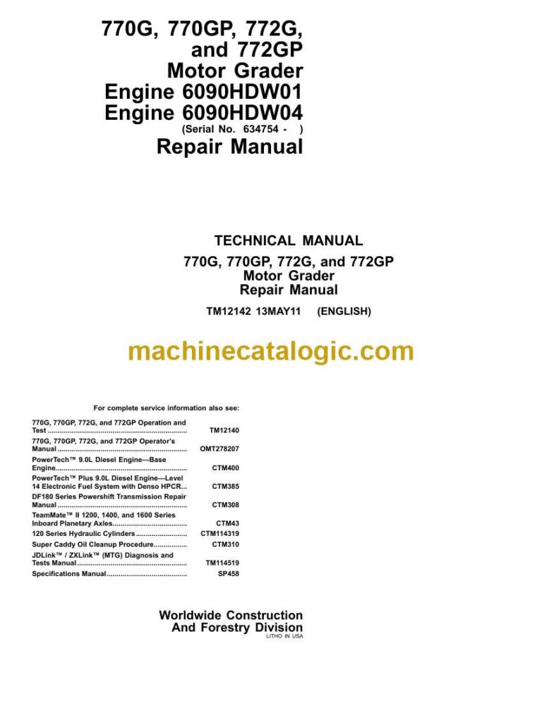
Model: 770G, 770GP, 772G, and 772GP Motor Grader

Book No: TM12142

Type of Document: Repair Technical Manual

Categories: ,

$ 40

Share:

John Deere 770G, 770GP, 772G, and 772GP Motor Grader Repair Technical Manual (TM12142)

John Deere 770G, 770GP, 772G, and 772GP Motor Grader Repair Technical Manual (TM12142)

📘 Show Index

John Deere 770G, 770GP, 772G, and 772GP Motor Grader Index:

  • Contents
    • General Information
      • Safety
        • Recognize Safety Information
        • Follow Safety Instructions
        • Operate Only If Qualified
        • Wear Protective Equipment
        • Avoid Unauthorized Machine Modifications
        • Inspect Machine
        • Stay Clear of Moving Parts
        • Avoid High-Pressure Fluids
        • Avoid High-Pressure Oils
        • Work In Ventilated Area
        • Prevent Fires
        • Prevent Battery Explosions
        • Handle Chemical Products Safely
        • Dispose of Waste Properly
        • Prepare for Emergencies
        • Clean Debris from Machine
        • Use Steps and Handholds Correctly
        • Start Only From Operator’s Seat
        • Use and Maintain Seat Belt
        • Prevent Unintended Machine Movement
        • Avoid Work Site Hazards
        • Keep Riders Off Machine
        • Avoid Backover Accidents
        • Avoid Machine Tip-Over
        • Operating Or Traveling On Public Roads
        • Inspect and Maintain ROPS
        • Add and Operate Attachments Safely
        • Park and Prepare for Service Safely
        • Service Cooling System Safely
        • Remove Paint Before Welding or Heating
        • Make Welding Repairs Safely
        • Drive Metal Pins Safely
        • Service Tires Safely
      • Torque Values
        • Metric Bolt and Cap Screw Torque Values
        • Additional Metric Cap Screw Torque Values
        • Unified Inch Bolt and Cap Screw Torque Values
        • Service Recommendations for 37° Flare and 30° Cone Seat Connecto
        • Service Recommendations for O-Ring Boss Fittings
        • Service Recommendations For Flared Connections—Straight or Taper
        • Service Recommendations For Flat Face O-Ring Seal Fittings
        • O-Ring Face Seal Fittings With SAE Inch Hex Nut And Stud End For
        • O-Ring Face Seal Fittings With Metric Hex Nut And Stud End For S
        • O-Ring Face Seal Fittings With Metric Hex Nut And Stud End For H
        • Service Recommendations for Metric Series Four Bolt Flange Fitti
        • Service Recommendations For Inch Series Four Bolt Flange Fitting
        • Inch Series Four Bolt Flange Fitting For High Pressure Service R
        • Service Recommendations For Non-Restricted Banjo (Adjustable) Fi
        • Service Recommendations For O-Ring Boss Fittings With Shoulder
        • Metric 24° O-Ring Seal DIN 20078 Service Recommendations
    • Wheels
      • Powered Wheels and Fasteners
        • Wheel Remove and Install
        • Tire Remove and Install
    • Axles and Suspension Systems
      • Input Drive Shafts and U-Joints
        • Transmission-to-Rear Axle Drive Shaft Remove and Install
        • Transmission-to-Rear Axle Drive Shaft Disassemble and Assemble
      • Non-Powered Wheel Axles
        • Front Wheel Hub and Spindle Remove and Install—Non 6WD
        • Front Wheel Hub and Spindle Disassemble and Assemble—Non 6WD
        • Front Axle Remove and Install—Non 6WD
      • Powered Wheel Axles
        • Front Wheel Hub and Spindle Remove and Install—6WD
        • Front Wheel Hub and Spindle Disassemble and Assemble—6WD
        • Front Wheel Hub and Spindle Disassemble and Assemble with Steeri
        • 6WD Drive Hub Disassemble and Assemble
        • Planetary Drive Disassemble and Assemble
        • Planetary Brake Disassemble and Assemble
        • 6WD Bearings Remove and Install
        • 6WD O-Ring Metal Face Seal Remove and Install
        • Front Axle Remove and Install—6WD
      • Axle Shafts, Bearings, and Reduction Gears
        • TEAMMATE™ II 1400 Series Inboard Planetary Axle—Use CTM43
        • Rear Axle Remove and Install
        • Tandem and Wheel Axle Assembly Remove and Install
        • Tandem Wheel Axle Assembly Remove and Install
        • Tandem Wheel Axle Assembly Disassemble and Assemble
        • Tandem Pivot Disassemble and Assemble
        • Final Drive Axle Remove and Install
        • Tandem Drive Shaft Remove and Install
        • Drive Chain Remove and Install
      • Hydraulic System
        • 6WD Pump Remove and Install
        • 6WD Pump Disassemble
        • 6WD Pump Assemble
        • 6WD Charge Pump Remove and Install
        • 6WD Engagement Manifold Remove and Install
        • Differential Lock Pump Remove and Install
        • 6WD Motor Remove and Install
        • 6WD Motor Disassemble and Assemble
    • Transmission
      • Removal and Installation
        • DF180 Transmission
        • Transmission Remove and Install
      • Hydraulic System
        • Transmission Charge Pump Remove and Install
    • Engine
      • Removal and Installation
        • John Deere Engine
        • Engine Remove and Install—Engine 6090HDW01
        • Engine Remove and Install—Engine 6090HDW04
    • Engine Auxiliary System
      • Cooling System
        • Fan Blade Remove and Install
        • Radiator Remove and Install
        • Hydraulic and Differential Oil Cooler Remove and Install
        • Transmission Oil Cooler Remove and Install
        • Fuel Cooler Remove and Install
        • Charge Air Cooler Remove and Install
      • External Fuel Supply Systems
        • Fuel Tank Remove and Install
        • Fast Fill Fuel System Disassemble and Assemble—If Equipped
    • Torsional Isolator
      • Elements
        • Torsional Isolator Remove and Install
    • Steering System
      • Power Steering
        • Toe-In Check and Adjustment
      • Hydraulic System
        • Steering Wheel, Column, and Valve Remove and Install—Standard Co
        • Steering Wheel, Column, and Valve Remove and Install—EH Controls
        • EH Controls Steering Canceling Valve Remove and Install
        • Steering Cylinder Remove and Install
        • Hydraulic Cylinder Disassemble and Assemble
        • Wheel Lean Cylinder Remove and Install
        • Secondary Steering Accumulator Remove and Install—If Equipped
    • Service Brakes
      • Active Elements
        • Service Brake Repair
      • Hydraulic System
        • Service Brake Valve Remove and Install
        • Service Brake Bleeding
        • Brake Accumulator Remove and Install
    • Park Brake
      • Active Elements
        • Park Brake Repair
    • Frame, Chassis or Supporting Structure
      • Frame Installation
        • Welding On Machine
        • Welding Repair of Major Structure
        • Separate Frames at Articulation Joint
        • Articulation Bearing Replacement
        • Rear Platform Remove and Install
    • Operator’s Station
      • Removal and Installation
        • Cab Remove and Install
        • Cab Remove and Install—GP Machine Only
      • Operator Enclosure
        • Windowpanes Remove and Install
        • Cab Door Handle Remove and Install
        • Cab Door Latch Remove and Install
        • Rivet Nut Installation
      • Pedal Assembly
        • Inching Pedal Remove and Install
      • Steering Tilt Console
        • Steering Support Console Remove and Install—Standard Controls
        • Steering Support Console Remove and Install—EH Controls
        • Console Tilt Remove and Install
        • Steering Tilt Assembly Remove and Install
      • Seat and Seat Belt
        • Seat Remove and Install
        • Seat Belt Remove and Install
        • Armrest Remove and Install
        • Armrest Remove and Install—EH Controls
        • Armrest Disassemble and Assemble—EH Controls
        • Standard Seat Disassemble and Assemble
        • Deluxe Seat Disassemble and Assemble
        • Air Suspension Disassemble and Assemble
      • Heating and Air Conditioning
        • R134a Refrigerant Cautions and Proper Handling
        • Flush and Purge Air Conditioner System
        • R134a Refrigerant Oil Information
        • R134a Refrigerant Recovery/Recycling and Charging Station Instal
        • R134a System Recover
        • R134a System Evacuate
        • R134a System Charge
        • Expansion Valve Remove and Install
        • Freeze Control Switch Remove and Install
        • High/Low Pressure Switch Remove and Install
        • Heater Control Valve Remove and Install
        • Heater Control Valve Leak Check
        • Blower Motor Assembly Remove and Install
        • Compressor Remove and Install
        • Condenser Remove and Install
        • Heater and Air Conditioner Remove and Install
        • Receiver-Dryer Remove and Install
        • Accumulator Remove and Install
    • Sheet Metal and Styling
      • Engine Enclosure
        • Engine Service Doors and Side Shields Remove and Install
        • Engine Covers Remove and Install
      • Grille and Grille Housing
        • Grille Housing Remove and Install
    • Main Hydraulic System
      • Hydraulic System
        • Vacuum Pump Installation
        • Hydraulic Pump Remove and Install
        • Hydraulic Pump Disassemble and Assemble
        • Hydraulic System Manifold Remove and Install
        • Hydraulic System Manifold Disassemble and Assemble
        • Soft Start Valve Remove and Install
        • Soft Start Valve Disassemble and Assemble
        • Hydraulic Fan Pump Remove and Install
        • Hydraulic Fan Motor Remove and Install
        • Hydraulic Fan Valve Remove and Install
        • Hydraulic Attenuator Remove and Install
        • General Oil Cleanup Procedure
        • Hydraulic/Hydrostatic Component Failure Cleanup Procedure
    • Grading Device
      • Controls Linkage
        • Control Linkage Remove and Install
      • Frames
        • NeverGrease™ Pin Joints
        • Lift Arms Remove and Install
        • Saddle Locking Cylinder Remove and Install
        • Saddle Frame Remove and Install
        • Blade Pitch Frame Remove and Install
        • Draft and Circle Frame Remove and Install
        • Circle Adjustment
        • Blade Side Shift Wear Inserts Remove and Install
      • Circle Gearbox
        • Circle Drive Gearbox Remove and Install
        • Circle Drive Gearbox Disassemble and Assemble
        • Circle Drive Gearbox (With Slip Clutch) Disassemble and Assemble
        • Circle Rotate Sensor Remove and Install
      • Hydraulic System
        • Grader Control Valve Remove and Install
        • Draft Frame Mount Grader Control Valve Remove and Install—EH Con
        • Cab Mount Grader Control Valve Remove and Install—EH Controls
        • Grader Control Valve Disassemble and Assemble
        • Midmount Scarifier Valve Section Disassemble and Assemble
        • Midmount Scarifier Valve Section Disassemble and Assemble—EH Con
        • Blade Lift Valve Section Disassemble and Assemble
        • Blade Lift Valve Section Disassemble and Assemble—EH Controls
        • Auxiliary (With Float) Valve Section Disassemble and Assemble
        • Auxiliary (Without Float) Valve Section Disassemble and Assemble
        • Auxiliary Valve Section Disassemble and Assemble—EH Controls
        • Wheel Lean, Articulation, Circle Side Shift, Blade Pitch, and Bl
        • Wheel Lean, Articulation, Circle Side Shift, Blade Pitch, Blade
        • Circle Rotate Valve Section Disassemble and Assemble
        • Circle Rotate Valve Section Disassemble and Assemble—EH Controls
        • Return Check Poppets Disassemble and Assemble
        • Circle Rotate Motor Disassemble and Assemble
        • Rotary Manifold Remove and Install
        • Blade Lift, Blade Pitch, and Circle Side Shift Cylinders Remove
        • Blade Side Shift Cylinder Remove and Install
        • Articulation Cylinders Remove and Install
    • Ground Conditioning Tool
      • Frames
        • NeverGrease™ Pin Joints
        • Scarifier/Blade Remove and Install
        • Midmount Scarifier Remove and Install
        • Midmount Scarifier Cylinder Remove and Install
        • Ripper Remove and Install
        • Ripper Cylinders Remove and Install
        • Balderson™ Style Front Lift Group Remove and Install
    • Dealer Fabricated Tools
      • Dealer Fabricated Tools
        • DF1057—Axle Adjusting Tool
        • DFT1101 Cab and ROPS Lift Bracket
        • DFT1151—Outboard Bearing Driver
        • DFT1152—Inboard Bearing Driver
        • DFT1225—Rolling Torque Measurement Tool
        • DFT1250 Lifting Bracket
        • DFT1282—King Pin Torque Adapter
        • DFT1308 Transmission Support Bracket
        • DFT1310—Cab Mount Control Valve Support Bracket
        • DFT1311—Extension for DFT1250

John Deere

Latest Product

0
    0
    Your Cart
    Your cart is emptyReturn to Shop