$ 0
0
$ 0
0

John Deere 315SL Backhoe Loader Operation and Test Technical Manual (TM13303X19)

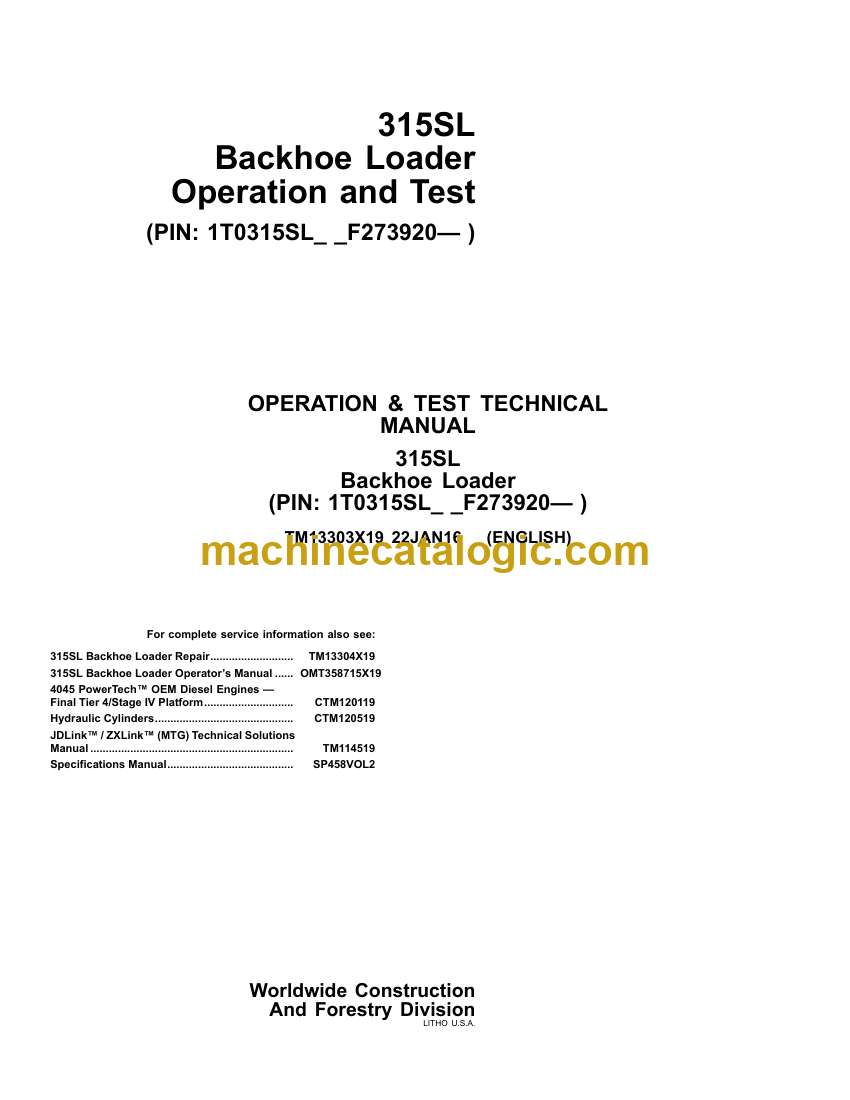
Format: PDF (Printable Document)

File Language: English

File Pages: 908

File Size: 37.26 MB (Speed Download Link)

Brand: John Deere

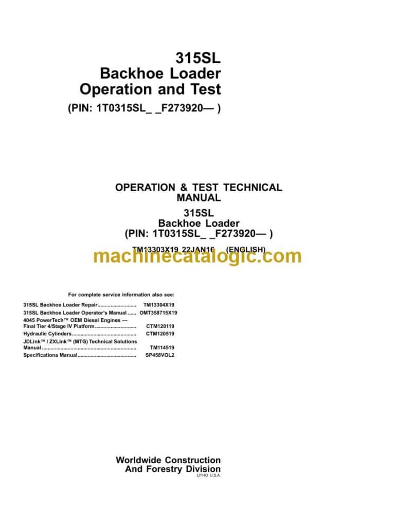
Model: 315SL Backhoe Loader

Book No: TM13303X19

Type of Document: Operation and Test Technical Manual

Categories: ,

$ 40

Share:

John Deere 315SL Backhoe Loader Operation and Test Technical Manual (TM13303X19)

John Deere 315SL Backhoe Loader Operation and Test Technical Manual (TM13303X19)

📘 Show Index

John Deere 315SL Backhoe Loader Index:

  • Contents
    • General Information
      • Safety
        • Recognize Safety Information
        • Follow Safety Instructions
        • Operate Only If Qualified
        • Wear Protective Equipment
        • Avoid Unauthorized Machine Modifications
        • Inspect Machine
        • Stay Clear of Moving Parts
        • Avoid High-Pressure Fluids
        • Avoid High-Pressure Oils
        • Work In Ventilated Area
        • Avoid Static Electricity Risk When Refueling
        • Prevent Fires
        • In Case of Machine Fire
        • Prevent Battery Explosions
        • Handle Chemical Products Safely
        • Decommissioning: Proper Recycling and Disposal of Fluids and Components
        • Exhaust Filter Ash Handling and Disposal
        • Prepare for Emergencies
        • Clean Debris from Machine
        • Use Steps and Handholds Correctly
        • Start Only From Operator’s Seat
        • Use and Maintain Seat Belt
        • Prevent Unintended Machine Movement
        • Prevent Unintended Machine Movement—If Equipped With Pilot Controls
        • Avoid Work Site Hazards
        • Keep Riders Off Machine
        • Avoid Backover Accidents
        • Avoid Machine Tipover
        • Operating or Traveling On Public Roads
        • Inspect and Maintain ROPS
        • Travel Safely
        • Prevent Acid Burns
        • Add and Operate Attachments Safely
        • Use Special Care When Operating
        • Park and Prepare for Service Safely
        • Service Cooling System Safely
        • Remove Paint Before Welding or Heating
        • Make Welding Repairs Safely
        • Drive Metal Pins Safely
        • Follow Tire Recommendations
        • Service Tires Safely
        • Clean Exhaust Filter Safely
    • Diagnostics
      • Engine Control Unit (ECU) Diagnostic Trouble Codes
        • Engine Control Unit (ECU) Diagnostic Trouble Codes
        • 000029.03 — Hand Throttle
        • 000029.04 — Hand Throttle
        • 000029.14 — Hand Throttle
        • 000091.03 — Foot Throttle
        • 000091.04 — Foot Throttle
        • 000091.14 — Foot Throttle
        • 000237.02 — Vehicle ID
        • 000237.13 — Vehicle ID
        • 000237.31 — Vehicle ID
        • 000647.05 — Engine Fan Driver
        • 000647.06 — Engine Fan Driver
        • 001321.05 — Starter Relay
        • 001321.06 — Starter Relay
        • 001321.09 — Starter Relay
        • 001321.16 — Starter Relay
        • 001321.31 — Starter Relay
        • 001639.01 — Fan Speed
        • 002003.09 — No CAN From TCU
        • 002071.09 — No CAN From VCU
        • 003353.31 — Alternator Output
        • 005927.05 — Coolant Pump
        • 005927.06 — Coolant Pump
        • 005927.07 — Coolant Pump
        • 524225.31 — Engine Start
      • Standard Display Monitor (SDM) Diagnostic Trouble Codes
        • Standard Display Monitor (SDM) Diagnostic Trouble Codes
        • 000096.03 — Fuel Level Sensor
        • 000096.04 — Fuel Level Sensor
        • 000168.03 — Battery Voltage
        • 000237.02 — Vehicle ID
        • 000237.13 — Vehicle ID
        • 000237.31 — Vehicle ID
        • 000628.12 — Programming
        • 000629.12 — Controller Fault
        • 000920.12 — Alarm Output
        • 001196.11 — Security
        • 002000.09 — No CAN from ECU
        • 002003.09 — No CAN from TCU
        • 002071.09 — No CAN from VCU
        • 002072.09 — System Message
        • 002251.09 — No CAN from MTG
        • 003509.03 — Sensor Supply 1
        • 003509.04 — Sensor Supply 1
        • 524082.07 — Display Buttons
      • Transmission Control Unit (TCU) Diagnostic Trouble Codes
        • Transmission Control Unit (TCU) Diagnostic Trouble Codes
        • 000070.14 — Park Brake
        • 000177.00 — Trans Oil Temp
        • 000177.04 — Trans Oil Temp
        • 000191.03 — Transmission Speed
        • 000191.04 — Transmission Speed
        • 000525.02 — Requested Gear
        • 000525.03 — Requested Gear
        • 000525.05 — Requested Gear
        • 000629.12 — Controller Fault
        • 000734.03 — Y1 Solenoid
        • 000734.04 — Y1 Solenoid
        • 000734.05 — Y1 Solenoid
        • 000734.06 — Y1 Solenoid
        • 000735.03 — Y2 Solenoid
        • 000735.04 — Y2 Solenoid
        • 000735.05 — Y2 Solenoid
        • 000735.06 — Y2 Solenoid
        • 000736.03 — Y3 Solenoid
        • 000736.05 — Y3 Solenoid
        • 000736.06 — Y3 Solenoid
        • 000737.03 — Y4 Solenoid
        • 000737.05 — Y4 Solenoid
        • 000737.06 — Y4 Solenoid
        • 000738.03 — Y5 Solenoid
        • 000738.05 — Y5 Solenoid
        • 000738.06 — Y5 Solenoid
        • 000739.03 — Y6 Solenoid
        • 000739.05 — Y6 Solenoid
        • 000739.06 — Y6 Solenoid
        • 000746.03 — Differential Lock
        • 000746.05 — Differential Lock
        • 000746.06 — Differential Lock
        • 000880.03 — Brake Lights
        • 000880.05 — Brake Lights
        • 000880.06 — Brake Lights
        • 002000.09 — System Message
        • 002023.09 — System Message
        • 002071.09 — System Message
        • 002072.09 — System Message
        • 002392.03 — Reverse Alarm
        • 002392.06 — Reverse Alarm
        • 002612.03 — MFWD Solenoid
        • 002612.05 — MFWD Solenoid
        • 002612.06 — MFWD Solenoid
        • 004312.02 — TCL Selector
        • 004312.03 — TCL Selector
        • 004312.05 — TCL Selector
        • 522379.03 — Park Brake
        • 522379.04 — Park Brake
        • 522379.05 — Park Brake
        • 522379.06 — Park Brake
        • 524172.03 — Clutch Disconnect
      • Vehicle Control Unit (VCU) Diagnostic Trouble Codes
        • Vehicle Control Unit (VCU) Diagnostic Trouble Codes
        • 000168.03 — Battery Voltage
        • 000237.02 — Vehicle ID
        • 000237.13 — Vehicle ID
        • 000237.31 — Vehicle ID
        • 000628.12 — Programming
        • 000629.12 — Control Unit
        • 001321.16 — Starter Relay
        • 001713.00 — Hyd Oil Restriction
        • 002142.09 — System Message
        • 002228.12 — EH Watchdog
        • 002347.03 — Front Light Switch
        • 002347.04 — Front Light Switch
        • 002350.06 — Drive Lights
        • 002354.06 — Front Work Lights
        • 002356.06 — Front Work Lights
        • 002360.06 — Rear Work Lights
        • 002362.06 — Rear Work Lights
        • 002366.06 — Side Work Lights
        • 002368.03 — Left Flasher
        • 002368.05 — Left Flasher
        • 002368.06 — Left Flasher
        • 002370.03 — Right Flasher
        • 002370.05 — Right Flasher
        • 002370.06 — Right Flasher
        • 002378.03 — Marker Light
        • 002378.05 — Marker Light
        • 002378.06 — Marker Light
        • 002863.02 — Wiper Switch
        • 002876.04 — Turn Signal Switch
        • 003509.03 — Sensor Supply 1
        • 003509.04 — Sensor Supply 1
        • 003997.03 — Accessory Relay
        • 003997.05 — Accessory Relay
        • 003997.06 — Accessory Relay
        • 004089.03 — Pump Out Pressure
        • 004089.04 — Pump Out Pressure
        • 520416.05 — Valve Power
        • 520546.07 — Pilot Enable Switch
        • 520688.03 — Pilot Enable Driver
        • 520688.05 — Pilot Enable Driver
        • 520688.06 — Pilot Enable Driver
        • 520696.03 — Pattern Select Driver
        • 520696.05 — Pattern Select Driver
        • 520696.06 — Pattern Select Driver
        • 520713.03 — Seat Position
        • 520713.04 — Seat Position
        • 520713.13 — Seat Position
        • 522312.03 — Front Washer
        • 522312.05 — Front Washer
        • 522312.06 — Front Washer
        • 522426.03 — Rear Wiper Park
        • 522426.04 — Rear Wiper Park
        • 522427.03 — Front Wiper Park
        • 522427.04 — Front Wiper Park
        • 522433.03 — Rear Wiper
        • 522433.05 — Rear Wiper
        • 522433.05 — Rear Wiper
        • 522434.03 — Front Wiper Low
        • 522434.05 — Front Wiper Low
        • 522434.06 — Front Wiper Low
        • 522435.03 — Front Wiper High
        • 522435.05 — Front Wiper High
        • 522435.06 — Front Wiper High
        • 523307.03 — Crank Signal
        • 523307.03 — Crank Signal
        • 523911.03 — Pump Control
        • 523911.04 — Pump Control
        • 523911.05 — Pump Control
        • 523911.06 — Pump Control
        • 523948.03 — Ride Control
        • 523948.05 — Ride Control
        • 523948.06 — Ride Control
      • Auxiliary Valve Controller (AVC) Diagnostic Trouble Codes
        • Auxiliary Valve Controller (AVC) Diagnostic Trouble Codes
        • 000168.03 — Battery Voltage
        • 000237.02 — Vehicle ID
        • 000237.13 — Vehicle ID
        • 000237.31 — Vehicle ID
        • 000629.12 — Control Unit
        • 002701.03 — BH Aux Roller
        • 002701.04 — BH Aux Roller
        • 002701.07 — BH Aux Roller
        • 002738.03 — Extendable Roller
        • 002738.04 — Extendable Roller
        • 002738.07 — Extendable Roller
        • 520425.07 — System Message
        • 520426.07 — System Message
        • 520542.03 — System Message
        • 520543.04 — System Message
        • 523934.00 — Extendable Sol A
        • 523934.01 — Extendable Sol A
        • 523934.03 — Extendable Sol A
        • 523934.04 — Extendable Sol A
        • 523934.05 — Extendable Sol A
        • 523934.06 — Extendable Sol A
        • 523940.00 — Extendable Sol B
        • 523940.01 — Extendable Sol B
        • 523940.03 — Extendable Sol B
        • 523940.04 — Extendable Sol B
        • 523940.05 — Extendable Sol B
        • 523940.06 — Extendable Sol B
        • 524010.00 — Selective Flow
        • 524010.01 — Selective Flow
        • 524010.03 — Selective Flow
        • 524010.04 — Selective Flow
        • 524010.05 — Selective Flow
        • 524010.06 — Selective Flow
      • Sealed Switch Module (SSM) Diagnostic Trouble Codes
        • Sealed Switch Module (SSM) Diagnostic Trouble Codes
        • 002033.09 — System Message
        • 002634.04 — Ignition Relay Circuit Fault
        • 002634.05 — Ignition Relay Circuit Fault
        • 521274.09 — System Message
        • 523850.04 — SSM Button Stuck
        • 523850.09 — System Message
        • 523852.04 — SSM Button Stuck
        • 523852.09 — System Message
        • 523854.04 — SSM Button Stuck
        • 523854.09 — System Message
        • 523855.04 — SSM Button Stuck
        • 523855.09 — System Message
        • 523856.04 — SSM Button Stuck
        • 523856.09 — System Message
        • 523857.04 — SSM Button Stuck
        • 523857.09 — System Message
        • 523858.04 — SSM Button Stuck
        • 523858.09 — System Message
        • 523860.04 — SSM Button Stuck
        • 523860.09 — System Message
        • 523861.04 — SSM Button Stuck
        • 523861.09 — System Message
        • 523862.04 — SSM Button Stuck
        • 523862.09 — System Message
        • 523863.04 — SSM Button Stuck
        • 523863.09 — System Message
        • 523864.04 — SSM Button Stuck
        • 523864.09 — System Message
        • 523865.04 — SSM Button Stuck
        • 523865.09 — System Message
        • 523867.04 — SSM Button Stuck
        • 523867.09 — System Message
        • 523868.04 — SSM Button Stuck
        • 523868.09 — System Message
      • Vehicle Control Unit 2 (VC2) Diagnostic Trouble Codes
        • Vehicle Control Unit 2 (VC2) Diagnostic Trouble Codes
        • 002664.03 — Ldr Aux Roller
        • 002664.04 — Ldr Aux Roller
        • 002664.07 — Ldr Aux Roller
        • 003509.03 — SENSOR SUPPLY 1
        • 003509.04 — SENSOR SUPPLY 1
        • 520669.00 — Loader Aux Pressure
        • 520669.01 — Loader Aux Pressure
        • 520669.03 — Loader Aux Sol A
        • 520669.04 — Loader Aux Sol A
        • 520669.05 — Loader Aux Sol A
        • 520669.06 — Loader Aux Sol A
        • 523404.00 — Backhoe Aux Pressure
        • 523404.01 — Backhoe Aux Pressure
        • 523935.03 — Backhoe Aux Sol A
        • 523935.04 — Backhoe Aux Sol A
        • 523935.05 — Backhoe Aux Sol A
        • 523935.06 — Backhoe Aux Sol A
    • Operational Checkout Procedure
      • Operational Checkout Procedure
        • Operational Checkout Procedure
          • Diagnostic Trouble Code (DTC) Check
          • Switched Power OFF, Engine OFF Checks
          • Switched Power ON, Engine OFF Checks
          • Switched Power ON, Engine ON Checks
    • Engine
      • Theory of Operation
        • John Deere Engine Operation
        • Engine Cooling System Operation
        • Cold Start Aid System Operation
      • System Diagrams
        • Engine Intake and Exhaust Component Location
        • Engine Fuel System Component Location
        • Engine Cooling System Component Location
      • Diagnostic Information
        • John Deere Engine Operation
      • Adjustments
        • John Deere Engine Operation
        • Service Filter Cleaning
      • Tests
        • John Deere Engine Operation
        • Fluid Sampling Procedure—If Equipped
        • Air in Fuel Test
        • Engine Speed Check
        • Engine Thermostat Test
        • Thermal Bypass Valve Test
        • Diesel Exhaust Fluid (DEF) Cooling System Test
    • Electrical System
      • Theory of Operation
        • Controller Area Network (CAN) Circuit Theory of Operation
        • Local Interconnect Network (LIN) Circuit Theory of Operation
        • Engine Control Unit (ECU) Circuit Theory of Operation
        • Vehicle Control Unit (VCU) Circuit Theory of Operation
        • Standard Display Monitor (SDM) Circuit Theory of Operation
        • Start and Charge Circuit Theory of Operation
        • Hydraulic System Circuit Theory of Operation
        • Transmission Control Circuit Theory of Operation
        • Exhaust Aftertreatment Circuit Theory of Operation
        • Auxiliary Valve Controller (AVC) Circuit Theory of Operation
        • Horn, Lights, and Beacon Circuit Theory of Operation
        • Wiper and Washer Circuit Theory of Operation
        • JDLink™ Circuit Theory of Operation
      • System Diagrams
        • Electrical Diagram Information
        • Electrical Schematic Symbols
        • System Functional Schematic and Section Legend
        • System Functional Schematic, Wiring Diagram, and Component Location Legend
        • Fuse and Relay Location and Specifications
        • Horn and Coolant Level Harness (W7) Wiring Diagram
        • Horn and Coolant Level Harness (W7) Component Location
        • Air Intake Heater Harness (W8) Wiring Diagram
        • Air Intake Heater Harness (W8) Component Location
        • Engine Harness (W10) Wiring Diagram
        • Engine Harness (W10) Component Location
        • Engine Interface Harness (W11) Wiring Diagram
        • Engine Interface Harness (W11) Component Location
        • Transmission Harness (W13) Wiring Diagram
        • Transmission Harness (W13) Component Location
        • Cab Harness (W14) Wiring Diagram
        • Cab Harness (W14) Component Location
        • Roof Harness (W17) Wiring Diagram
        • Roof Harness (W17) Component Location
        • Heater and Air Conditioner Harness (W19) Wiring Diagram
        • Heater and Air Conditioner Harness (W19) Component Location
        • Auxiliary Valve Control Harness (W23) Wiring Diagram
        • Auxiliary Valve Control Harness (W23) Component Location
        • Ride Control Solenoid Harness (W27) Wiring Diagram
        • Ride Control Solenoid Harness (W27) Component Location
        • Selective Flow Solenoid Harness (W28) Wiring Diagram
        • Selective Flow Solenoid Harness (W28) Component Location
        • Loader Auxiliary Solenoid Harness (W29) Wiring Diagram
        • Loader Auxiliary Solenoid Harness (W29) Component Location
        • Pilot Enable Pattern Select Valve Harness (W30) Wiring Diagram
        • Pilot Enable Pattern Select Valve Harness (W30) Component Location
        • Pilot Enable Switch Harness (W31) Wiring Diagram
        • Pilot Enable Switch Harness (W31) Component Location
        • Return-to-Dig Harness (W32) Wiring Diagram
        • Return-to-Dig Harness (W32) Component Location
        • Rear Frame Harness (W38) Wiring Diagram
        • Rear Frame Harness (W38) Component Location
        • Air Conditioner Compressor Clutch Harness (W39) Wiring Diagram
        • Air Conditioner Compressor Clutch Harness (W39) Component Location
        • Pilot Control and Selective Flow Harness (W40) Wiring Diagram
        • Pilot Control and Selective Flow Harness (W40) Component Location
        • Auxiliary Hydraulic Foot Switch Harness (W47) Wiring Diagram—If Equipped
        • Auxiliary Hydraulic Foot Switch Harness (W47) Component Location—If Equipped
        • Variable Speed Fan Harness (W48) Wiring Diagram
        • Variable Speed Fan Harness (W48) Component Location
        • Diesel Exhaust Fluid (DEF) Harness (W49) Wiring Diagram
        • Diesel Exhaust Fluid (DEF) Harness (W49) Component Location
        • Aftertreatment Harness (W50) Wiring Diagram
        • Aftertreatment Harness (W50) Component Location
        • Radio Harnesses (W51, W52, W53, and W54) Wiring Diagrams
        • Radio Harnesses (W51, W52, W53, W54, and W55) Component Location
        • Blower Mode Door Motor Harness (W56) Wiring Diagram
        • Blower Mode Door Motor Harness (W56) Component Location
        • Fuel Injector Harness (W57) Wiring Diagram
        • Fuel Injector Harness (W57) Component Location
        • Modular Telematics Gateway (MTG) Harness (W6002) Wiring Diagram—Without SAT
        • Modular Telematics Gateway (MTG) Harness (W6002) Component Location
        • Satellite (SAT) Harness (W6003) Wiring Diagram
        • Satellite (SAT) Harness (W6003) Component Location
      • Diagnostic Information
        • Electrical Component Specifications
        • Service ADVISOR™ Diagnostic Application
        • Service ADVISOR™ Connection Procedure
        • Reading Diagnostic Trouble Codes (DTCs) With Service ADVISOR™ Diagnostic Application
        • Intermittent Diagnostic Trouble Code (DTC) Diagnostics
        • Using Service ADVISOR™ Remote
        • JDLink™ Connection Procedure
      • Monitor Operation
        • Service Mode
        • Operation—Exhaust Filter Service Cleaning
        • Operation—Software Delivery
        • Diagnostics—Clear Stored Diagnostic Trouble Codes (DTCs)
        • Diagnostics—Engine
        • Diagnostics—Electrical, Lights
        • Diagnostics—Transmission
        • Diagnostics—Hydraulics
        • Diagnostics—Buttons
        • Diagnostics—Service Advisor
        • Diagnostics—Sensors
        • Setup—Monitor
        • Setup—Auto-Idle
        • Setup—Auto-Shutdown
        • Setup—Calibrations
        • Setup—Ignition Shutdown
        • Setup—High Altitude Mode
        • Setup—Transmission
      • Diagnostic Test Box
        • Setup and Functional Test
        • Two Wire Sensor Circuit Check—Out of Range High
        • Two Wire Sensor Circuit Check—Out of Range Low
        • Three Wire Sensor Circuit Check—Out of Range High
        • Three Wire Sensor Circuit Check—Out of Range Low
      • Tests
        • Controller Area Network (CAN) Circuit Test
          • Controller Area Network (CAN) Diagnostics
        • Controller Area Network (CAN) Resistor Test
        • Auxiliary Selective Flow Control Circuit Test
        • Throttle Position Sensor Test
        • Alternator Test
        • Relay Test
        • Wire Harness Test
        • Sensor Circuit Test
        • Engine Speed Control Pedal Test
          • Engine Speed Control Pedal Test Diagnostic Procedure
    • Power Train
      • Theory of Operation
        • Power Train Overview
        • Transmission Pump Operation
        • Torque Converter Operation
        • Clutch Modulation Operation
        • Clutch Pack Operation
        • Clutch Engagement and Solenoid Activation
        • Transmission Gear Flow
        • Differential Operation
        • Differential Lock Operation
        • Mechanical Front Wheel Drive (MFWD) Operation—If Equipped
        • Mechanical Front Wheel Drive (MFWD) Differential Operation—If Equipped
        • Park Brake Operation
        • Power Boost Service Brake Valve Operation
        • Service Brake Operation
        • Transmission Filter Operation
      • System Diagrams
        • Power Train Component Location
        • Power Train Schematic—First Forward
        • Power Train Schematic—Neutral
      • Diagnostic Information
        • Diagnose Transmission Malfunctions
        • Transmission Overheats
          • Transmission Overheats Diagnostic Procedure
        • Transmission Slippage
          • Transmission Slippage Diagnostic Procedure
        • Excessive Power Train Noise
          • Excessive Power Train Noise Diagnostic Procedure
        • No Differential Lock Operation
          • No Differential Lock Operation Diagnostic Procedure
        • Differential Lock Slips or Chatters When Engaged
          • Differential Lock Slips or Chatters When Engaged Diagnostic Procedure
        • Differential Lock Will Not Release
          • Differential Lock Will Not Release Diagnostic Procedure
        • Machine Lacks Power or Moves Slow
          • Machine Lacks Power or Moves Slow Diagnostic Procedure
        • No Power to Mechanical Front Wheel Drive (MFWD)
          • No Power to Mechanical Front Wheel Drive (MFWD) Diagnostic Procedure
        • No Power to One Wheel of Mechanical Front Wheel Drive (MFWD)
          • No Power to One Wheel of Mechanical Front Wheel Drive (MFWD) Diagnostic Procedure
        • Park Brake Will Not Hold
          • Park Brake Will Not Hold Diagnostic Procedure
        • Park Brake Will Not Release
          • Park Brake Will Not Release Diagnostic Procedure
        • Poor Service Brakes
          • Poor Service Brakes Diagnostic Procedure
        • Service Brakes Chatter or Noisy
          • Service Brakes Chatter or Noisy Diagnostic Procedure
        • Service Brakes Will Not Release
          • Service Brakes Will Not Release Diagnostic Procedure
        • Rear Axle Overfilled With Oil
          • Rear Axle Overfilled With Oil Diagnostic Procedure
      • Adjustments
        • Mechanical Park Brake Release—Towing
        • Service Brake Bleed Procedure
        • Service Brake Pedal Adjustment
        • Steering Angle Check and Adjust
        • Toe-In Check and Adjust
        • Tracking Angle Check and Adjust
      • Tests
        • Transmission Overall Test Connections, Ports, and Locations
        • Transmission Oil Warm-Up Procedure
        • Transmission Pump Flow Test
        • Transmission System Pressure Test
        • Transmission Oil Sampling Procedure—If Equipped
        • Torque Converter Stall Speed Test
        • Torque Converter-In Relief Valve Test
        • Clutch Pressure Test
        • Solenoid Circuit Leakage Test
        • Differential Lock Pressure Test
        • Mechanical Front Wheel Drive (MFWD) Pressure Test
        • Park Brake Release Pressure Test
        • Power Boost Service Brake Valve Leakage Test
        • Cooler In and Cooler Out Pressure Test
    • Hydraulic System
      • Theory of Operation
        • Hydraulic System Operation
        • Hydraulic Pump Operation
        • Hydraulic Filter Operation
        • System and Circuit Relief Valve Operation
        • Backhoe Control Valve Operation
        • Sideshift and Boom Lock (SBL) Valve Operation
        • Pilot Control Valve Operation
        • Pilot Enable and Pattern Select Valve Operation—If Equipped
        • Loader and Stabilizer Control Valve Operation
        • Loader Auxiliary Control Operation
        • Ride Control Operation—If Equipped
        • Steering Valve Operation
      • System Diagrams
        • Hydraulic System Schematic
        • Hydraulic System Component Location
        • Hydraulic Main System Line Identification
        • Hydraulic Backhoe System Line Identification
        • Hydraulic Backhoe Pilot Controls System Line Identification
        • Hydraulic Loader System Line Identification
        • Hydraulic Ride Control System Line Identification
        • Hydraulic Brake and Steering System Line Identification
        • Hydraulic Sideshift and Boom Lock (SBL) System Line Identification
      • Diagnostic Information
        • Low Hydraulic Power
          • Low Hydraulic Power Diagnostic Procedure
        • Slow Hydraulic Functions
          • Slow Hydraulic Functions Diagnostic Procedure
        • Hydraulic Function Makes “Chattering” Noise
          • Hydraulic Function Makes “Chattering” Noise Diagnostic Procedure
        • Hydraulic Oil Overheats
          • Hydraulic Oil Overheats Diagnostic Procedure
        • Hydraulic Pump Leaking
          • Hydraulic Pump Leaking Diagnostic Procedure
        • Excessive Pump Noise
          • Excessive Pump Noise Diagnostic Procedure
        • Foaming Oil
          • Foaming Oil Diagnostic Procedure
        • Functions Drift
          • Functions Drift Diagnostic Procedure
        • Control Valve Sticks or Works Hard
          • Control Valve Sticks or Works Hard Diagnostic Procedure
        • No Loader or Steering Hydraulics
          • No Loader or Steering Hydraulics Diagnostic Procedure
        • No Backhoe Power in One Function
          • No Backhoe Power in One Function Diagnostic Procedure
        • Backhoe Operates Slowly in One Function
          • Backhoe Operates Slowly in One Function Diagnostic Procedure
        • Engine Pulls Down Excessively During Backhoe Operation
          • Engine Pulls Down Excessively During Backhoe Operation Diagnostic Procedure
        • No Loader Hydraulics
          • No Loader Hydraulics Diagnostic Procedure
        • No Loader Power in One Function
          • No Loader Power in One Function Diagnostic Procedure
        • Low Loader Hydraulic Power
          • Low Loader Hydraulic Power Diagnostic Procedure
        • Loader Operates Slowly in One Function
          • Loader Operates Slowly in One Function Diagnostic Procedure
        • Engine Pulls Down Excessively During Loader Operation
          • Engine Pulls Down Excessively During Loader Operation Diagnostic Procedure
        • Erratic “Spongy” Steering
          • Erratic (“Spongy”) Steering Diagnostic Procedure
        • Hard Steering, Loader Hydraulics OK
          • Hard Steering, Loader Hydraulics OK Diagnostic Procedure
        • No Response When Steering Wheel is Turned, Loader Hydraulics OK
          • No Response When Steering Wheel is Turned, Loader Hydraulics OK Diagnostic Procedure
        • Slow Steering Hydraulics
          • Slow Steering Hydraulics Diagnostic Procedure
        • Excessive Steering Wheel Turns to Steer Machine
          • Excessive Steering Wheel Turns to Steer Machine Diagnostic Procedure
        • Excessive Vibration of the Steering Wheel
          • Excessive Vibration of the Steering Wheel Diagnostic Procedure
        • Machine Turns in Opposite Direction
          • Machine Turns in Opposite Direction Diagnostic Procedure
        • Machine Turns When Steering Valve is in Neutral
          • Machine Turns When Steering Valve is in Neutral Diagnostic Procedure
        • Poor Centering of Steering Wheel (Wheels Continue to Move After Steering Wheel is Stopped)
          • Poor Centering of Steering Wheel (Wheels Continue to Move After Steering Wheel is Stopped) Diagnostic Procedure
        • Steering Valve Does Not Return to Neutral
          • Steering Valve Does Not Return to Neutral Diagnostic Procedure
        • Steering Wheel Kickback
          • Steering Wheel Kickback Diagnostic Procedure
        • Steering Wheel “Locks” Up
          • Steering Wheel “Locks” Up Diagnostic Procedure
        • Steering Wheel or Front Wheels Slowly Turn by Themselves When Using Backhoe or Loader
          • Steering Wheel or Front Wheels Slowly Turn by Themselves When Using Backhoe or Loader Diagnostic Procedure
        • Steering Wheel Turns Apply Rear Axle Service Brakes
          • Steering Wheel Turns Apply Rear Axle Service Brakes Diagnostic Procedure
        • Steering Wheel Turns Freely With No Resistance or Action On Steered Wheels
          • Steering Wheel Turns Freely With No Resistance or Action On Steered Wheels Diagnostic Procedure
        • Steering Wheel Turns With Slight Resistance and No Action On Steered Wheels
          • Steering Wheel Turns With Slight Resistance and No Action On Steered Wheels Diagnostic Procedure
        • Wander—Machine Will Not Stay in a Straight Line
          • Wander—Machine Will Not Stay in a Straight Line Diagnostic Procedure
      • Adjustments
        • Backhoe Control Lever Adjustment—Two-Lever
        • Backhoe Control Lever Adjustment—Four-Lever (If Equipped)
        • Auxiliary Selective Flow Control Valve Adjustment—If Equipped
        • Pilot Control Pressure Adjustment
        • Pilot Enable and Pattern Select (PEPS) Valve Accumulator Discharge Procedure
        • Loader Bucket Self-Leveling Linkage and Return-To-Dig Switch Adjustment
        • Ride Control Accumulator Charge Procedure
        • Ride Control Accumulator Charge Check Procedure
        • Ride Control Accumulator Hydraulic Pressure Release Procedure
      • Tests
        • Hydraulic System Pressure Test
        • Circuit Relief Valve Test—With Remote Pump
        • Function Drift Test
        • Hydraulic Circuit Pressure Release
        • Hydraulic Cylinder Leakage Test
        • Hydraulic Oil Cooler Restriction Test
        • Hydraulic Oil Warm-Up Procedure
        • Hydraulic Pump Flow Test
        • Hydraulic Pump Unloading Relief Valve Pressure Test
        • JT02156A Digital Pressure and Temperature Analyzer Kit Installation
        • Loader and Stabilizer Control Valve Lockout Leakage Test
        • Pilot Control Accumulator Charge Pressure Test
        • Pilot Control Pressure Test
        • Steering Cylinder Leakage Test
        • Steering System Leakage Test
    • Heating and Air Conditioning
      • Theory of Operation
        • Air Conditioning System Cycle of Operation
      • System Diagrams
        • Heating and Air Conditioning System Component Location
      • Diagnostic Information
        • Air Conditioning System Does Not Operate
          • Air Conditioning System Does Not Operate Diagnostic Procedure
        • Air Conditioning System Does Not Cool Interior of Cab
          • Air Conditioner Does Not Cool Interior of Cab Diagnostic Procedure
        • Air Conditioning System Runs Constantly, Too Cold
          • Air Conditioning System Runs Constantly, Too Cold Diagnostic Procedure
        • Heating System Does Not Operate
          • Heating System Does Not Operate Diagnostic Procedure
        • Heating System Does Not Warm Interior of Cab
          • Heating System Does Not Warm Interior of Cab Diagnostic Procedure
        • Interior Windows Continue to Fog
          • Interior Windows Continue to Fog Diagnostic Procedure
      • Tests
        • R134a Refrigerant Cautions and Proper Handling
        • R134a Oil Charge Capacity
        • R134a Refrigerant Charge Capacity
        • Heater and Air Conditioner Operational Checks
          • Visual Inspection of Components
        • Air Conditioner Compressor Clutch Test
        • R134a Refrigerant Leak Test
        • R134a Refrigerant Hoses and Tubing Inspection
        • Air Conditioner High/Low-Pressure Switch Test
        • Air Conditioner Freeze Control Switch Test
        • Air Conditioning System Test
        • Operating Pressure Diagnostic Chart
  • Page Number
    • Section 9000
      • Group 01
    • Section 9001
      • Group 10
      • Group 20
      • Group 30
      • Group 40
      • Group 50
      • Group 60
      • Group 70
    • Section 9005
      • Group 10
    • Section 9010
      • Group 05
      • Group 10
      • Group 15
      • Group 20
      • Group 25
    • Section 9015
      • Group 05
      • Group 10
      • Group 15
      • Group 16
      • Group 17
      • Group 25
    • Section 9020
      • Group 05
      • Group 10
      • Group 15
      • Group 20
      • Group 25
    • Section 9025
      • Group 05
      • Group 10
      • Group 15
      • Group 20
      • Group 25
    • Section 9031
      • Group 05
      • Group 10
      • Group 15
      • Group 25

John Deere

Latest Product

0
    0
    Your Cart
    Your cart is emptyReturn to Shop