John Deere 318D and 320D Skid Steer Loader Operation and Test Technical Manual (TM11398)
Machine throws a derate code, hydraulics are crawling, customer breathing down your neck. You can guess at fuel, filters, or sensors, or you can open TM11398 and go straight to the exact test for that code. It tells you which circuit, which connector, what voltage or pressure you should see. No wandering around the machine, no “let’s try this” parts swapping. You follow the test tree, you find the failed sensor, broken wire, or weak pump, and you’re back loading trucks instead of chasing ghosts.
Key Tasks Covered:
- Trace specific ECU derate codes to exact circuits and components.
- Run step‑by‑step hydraulic pressure and flow tests on the main pump and drive pumps.
- Check joystick and pedal input values through the controller diagnostics.
- Verify charge pressure, case drain, and relief valve settings on the hydrostatic system.
- Diagnose no‑start or hard‑start using the fuel and electrical test procedures.
Common Questions:
Q: “Hydraulics are slow but pressures look fine. Now what?”
A: TM11398 walks you through checking charge pressure, case drain flow, and control signal to the proportional valves—usually exposes a weak pump or a starving circuit.
Q: “Why’s it stuck in derate after I changed the sensor?”
A: Because the manual shows you you’ve gotta confirm reference voltage, signal return, and then clear the code with the correct key‑on/off cycle or service tool.
Safety Note
Lock out the boom and kill hydraulic pressure before cracking any lines—oil at 3,000 psi doesn’t forgive mistakes.
John Deere 318D and 320D Skid Steer Loader Index:
- Contents
- General Information
- Safety
- Recognize Safety Information
- Follow Safety Instructions
- Operate Only If Qualified
- Wear Protective Clothing
- Avoid Unauthorized Machine Modifications
- Inspect Machine
- Stay Clear of Moving Parts
- Avoid High-Pressure Fluids
- Avoid High-Pressure Oils
- Work In Ventilated Area
- Prevent Fires
- Prevent Battery Explosions
- Handle Chemical Products Safely
- Dispose of Waste Properly
- Prepare for Emergencies
- Clean Debris from Machine
- Use Steps and Handholds Correctly
- Start Only From Operator’s Seat
- Use and Maintain Seat Belt
- Prevent Unintended Machine Movement
- Avoid Work Site Hazards
- Keep Riders Off Machine
- Avoid Backover Accidents
- Avoid Machine Tip Over
- Operating On Slopes
- Operating Or Traveling On Public Roads
- Inspect and Maintain ROPS
- Add and Operate Attachments Safely
- Park and Prepare for Service Safely
- Service Cooling System Safely
- Remove Paint Before Welding or Heating
- Make Welding Repairs Safely
- Drive Metal Pins Safely
- Service Tires Safely
- Handle Cab Door Safely
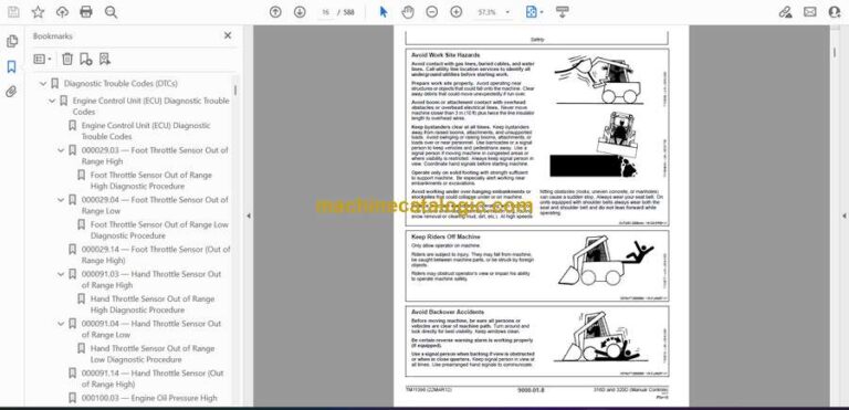
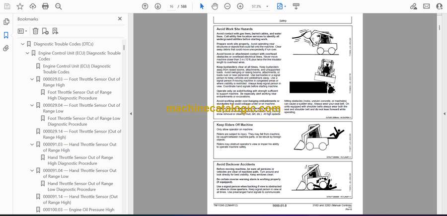
- Diagnostic Trouble Codes (DTCs)
- Engine Control Unit (ECU) Diagnostic Trouble Codes
- Engine Control Unit (ECU) Diagnostic Trouble Codes
- 000029.03 — Foot Throttle Sensor Out of Range High
- Foot Throttle Sensor Out of Range High Diagnostic Procedure
- 000029.04 — Foot Throttle Sensor Out of Range Low
- Foot Throttle Sensor Out of Range Low Diagnostic Procedure
- 000029.14 — Foot Throttle Sensor (Out of Range High)
- 000091.03 — Hand Throttle Sensor Out of Range High
- Hand Throttle Sensor Out of Range High Diagnostic Procedure
- 000091.04 — Hand Throttle Sensor Out of Range Low
- Hand Throttle Sensor Out of Range Low Diagnostic Procedure
- 000091.14 — Hand Throttle Sensor (Out of Range High)
- 000100.03 — Engine Oil Pressure High
- 000107.00 — Engine Air Filter Switch Data Above Normal
- Engine Air Filter Switch Data Above Normal Diagnostic Procedure
- 000171.03 — Ambient Air Temperature Out of Range High
- Ambient Air Temperature Out of Range High Diagnostic Procedure
- 000171.04 — Ambient Air Temperature Out of Range Low
- Ambient Air Temperature Out of Range Low Diagnostic Procedure
- 000237.13 — Vehicle Identification Number
- 000647.05 — Fan Coil Output Driver Out of Range Low
- Fan Coil Output Driver Out of Range Low Diagnostic Procedure
- 000647.06 — Fan Coil Output Driver Out of Range High
- Fan Coil Output Driver Out of Range High Diagnostic Procedure
- 000647.30 — Fan Coil Output Driver Unknown Fault
- Fan Coil Output Driver Unknown Fault Diagnostic Procedure
- 000676.05 — Glow Plug Relay Output Out of Range Low
- Glow Plug Relay Output Out of Range Low Diagnostic Procedure
- 000676.06 — Glow Plug Relay Output Out of Range High
- Glow Plug Relay Output Out of Range High Diagnostic Procedure
- 001110.31 — Engine Protection Has Shut Down Engine
- 001321.05 — Starter Relay Output Out of Range Low
- Starter Relay Output Out of Range Low Diagnostic Procedure
- 001321.06 — Starter Relay Output Out of Range High
- Starter Relay Output Out of Range Low Diagnostic Procedure
- 001321.16 — Starter Relay Output Moderately High Value
- 001508.00 — Hydraulic Oil Temperature Data Above Normal
- Hydraulic Oil Temperature Data Above Normal Diagnostic Procedure
- 001508.03 — Hydraulic Oil Temperature Out of Range High
- Hydraulic Oil Temperature Out of Range High Diagnostic Procedure
- 001508.04 — Hydraulic Oil Temperature Out of Range Low
- Hydraulic Oil Temperature Out of Range Low Diagnostic Procedure
- 001713.00 — Hydraulic Filter Restriction Switch Data Above Norma
- Hydraulic Filter Restriction Switch Data Above Normal Diagnostic
- 002023.09 — No EMU on CAN Bus Abnormal Data Rate
- No EMU Data on CAN Bus Abnormal Data Range Diagnostic Procedure
- 522826.05 — Fan Reversing Coil Output Out of Range Low
- Fan Reversing Coil Output Out of Range Low Diagnostic Procedure
- 522826.06 — Fan Reversing Coil Output Out of Range High
- Fan Reversing Coil Output Out of Range High Diagnostic Procedure
- Engagement and Monitor Unit (EMU) Diagnostic Trouble Codes
- Engagement and Monitor Unit (EMU) Diagnostic Trouble Codes
- 000070.02 — Park Brake Release Input Erratic or Bad Data
- Park Brake Release Input Erratic or Bad Data Diagnostic Procedur
- 000070.04 — Park Brake Release Input Out of Range Low
- Park Brake Release Input Out of Range Low Diagnostic Procedure
- 000096.03 — Fuel Level Sensor Out of Range High
- Fuel Level Sensor Out of Range High Diagnostic Procedure
- 000096.04 — Fuel Level Sensor Out of Range Low
- Fuel Level Sensor Out of Range Low Diagnostic Procedure
- 000158.00 — System Voltage Data Above Normal
- System Voltage Data Above Normal Diagnostic Procedure
- 000158.01 — System Voltage Data Below Normal
- System Voltage Data Below Normal Diagnostic Procedure
- 000162.04 — 2-Speed Switch Input Out of Range Low
- Switch Input Low Diagnostic Procedure—Manual Control Machines
- Switch Input Low Diagnostic Procedure—EH Control Machines
- 000920.05 — Alarm Output Out of Range Low
- Alarm Output Out of Range Low Diagnostic Procedure
- 000920.06 — Alarm Output Out of Range High
- Alarm Output Out of Range High Diagnostic Procedure
- 001196.11 — Anti Theft Unknown Fault
- Anti Theft Unknown Fault Diagnostic Procedure
- 001504.04 — Seat Switch Input Out of Range Low
- Seat Switch Input Out of Range Low Diagnostic Procedure
- 001550.05 — AC Compressor Clutch Output Out of Range Low
- AC Compressor Clutch Output Out of Range Low Diagnostic Procedur
- 001550.06 — AC Compressor Clutch Output Out of Range High
- AC Compressor Clutch Output Out of Range High Diagnostic Procedu
- 002000.09 — No ECU Data on CAN Bus Abnormal Data Range
- No ECU Data on CAN Bus Abnormal Data Range Diagnostic Procedure
- 002228.09 — No HCU Data on CAN Bus Abnormal Data Range
- No HCU Data on CAN Bus Abnormal Data Range Diagnostic Procedure
- 003413.04 — Door Switch Input Out of Range Low
- Seat Switch Input Out of Range Low Diagnostic Procedure
- 003597.03 — 5 Volt Sensor Supply 1 Out of Range High
- Sensor Supply Voltage High Diagnostic Procedure—Manual Control M
- Sensor Supply Voltage High Diagnostic Procedure—EH Control Machi
- 003597.04 — 5 Volt Sensor Supply 1 Out of Range Low
- Sensor Supply Voltage Low Diagnostic Procedure—Manual Control Ma
- Sensor Supply Voltage Low Diagnostic Procedure—EH Control Machin
- 520850.04 — Over Ride Switch Input Out of Range Low
- Over Ride Switch Input Out of Range Low Diagnostic Procedure
- 521050.04 — Aux Flow On-Off Switch Input Out of Range Low
- Switch Input Low Diagnostic Procedure—Manual Control Machines
- Switch Input Low Diagnostic Procedure—EH Control Machines
- 522379.05 — Park Brake Release Output Out of Range Low
- Park Brake Release Output Out of Range Low Diagnostic Procedure
- 522379.06 — Park Brake Release Output Out of Range High
- Park Brake Release Output Out of Range High Diagnostic Procedure
- 522398.02 — Park Brake Run Switch Input Erratic or Bad Data
- Park Brake Release Input Erratic or Bad Data Diagnostic Procedur
- 522398.04 — Park Brake Run Switch Input Out of Range Low
- Park Brake Release Input Out of Range Low Diagnostic Procedure
- 522820.05 — High Flow Driver Out of Range Low
- High Flow Driver Out of Range Low Diagnostic Procedure
- 522820.06 — High Flow Driver Out of Range High
- High Flow Driver Out of Range High Diagnostic Procedure
- 522826.04 — VSF Purge Switch Input Out of Range Low
- VSF Purge Switch Input Out of Range Low Diagnostic Procedure
- 522827.04 — VSF Auto Switch Input Out of Range Low
- VSF Purge Switch Input Out of Range Low Diagnostic Procedure
- 522828.04 — Creep Mode Switch Input Out of Range Low
- Creep Mode Switch Input Out of Range Low Diagnostic Procedure
- 522859.04 — Lap Bar Switch Input Out of Range Low
- Lap Bar Switch Input Out of Range Low Diagnostic Procedure
- 523217.06 — Hydraulic Valve Power 3 Out of Range High
- Hydraulic Valve Power 3 Out of Range High Diagnostic Procedure—M
- Hydraulic Valve Power 3 Out of Range High Diagnostic Procedure—E
- 523218.06 — Propel Valve Power 2 to HCU Out of Range High
- Propel Valve Power 2 to HCU Out of Range High Diagnostic Procedu
- 523219.06 — Hydraulic Valve Power 1 Out of Range High
- Hydraulic Valve Power 1 Out of Range High Diagnostic Procedure—M
- Hydraulic Valve Power 1 Out of Range High Diagnostic Procedure—E
- 523693.03 — Aux Hyd Channel 1 Input Out of Range High
- Aux Hyd Channel 1 Input High Diagnostic Procedure—Manual Control
- Aux Hyd Channel 1 Input High Diagnostic Procedure—EH Control Mac
- 523693.04 — Aux Hyd Channel 1 Input Out of Range Low
- Aux Hyd Channel 1 Input Low Diagnostic Procedure—Manual Control
- Aux Hyd Channel 1 Input Low Diagnostic Procedure—EH Control Mach
- 523694.03 — Aux Hyd Channel 2 Input Out of Range High
- Aux Hyd Channel 2 Input High Diagnostic Procedure—Manual Control
- Aux Hyd Channel 2 Input High Diagnostic Procedure—EH Control Mac
- 523694.04 — Aux Hyd Channel 2 Input Out of Range Low
- Aux Hyd Channel 2 Input Low Diagnostic Procedure—Manual Control
- Aux Hyd Channel 2 Input Low Diagnostic Procedure—EH Control Mach
- 523694.12 — Aux Hyd Channel 2 Input Device Fault
- Aux Hyd Channel 2 Input Device Fault Diagnostic Procedure
- 523822.04 — High Flow Switch Input Out of Range Low
- High Flow Switch Input Out of Range Low Diagnostic Procedure
- 523917.05 — Two Speed Output Out of Range Low
- Two Speed Output Out of Range Low Diagnostic Procedure
- 523917.06 — Two Speed Output Out of Range High
- Two Speed Output Out of Range High Diagnostic Procedure
- 523935.05 — Aux Hyd Extend Output Out of Range Low
- Aux Hyd Extend Output Out of Range Low Diagnostic Procedure
- 523935.06 — Aux Hyd Extend Output Out of Range High
- Aux Hyd Extend Output Out of Range High Diagnostic Procedure
- 523941.05 — Aux Hyd Retract Output Out of Range Low
- Aux Hyd Extend Output Out of Range Low Diagnostic Procedure
- 523941.06 — Aux Hyd Retract Output Out of Range High
- Aux Hyd Retract Output Out of Range High Diagnostic Procedure
- 524225.04 — Remote Start Input Out of Range Low
- Remote Start Input Out of Range Low Diagnostic Procedure
- 524264.11 — Checksum Error Unknown Fault
- Checksum Error Unknown Fault Diagnostic Procedure
- Operational Checkout Procedure
- Operational Checkout Procedure
- Operational Checkout
- Key Switch OFF, Engine OFF Checks
- Key Switch ON, Engine OFF Checks
- Key Switch ON, Engine ON Checks
- Engine
- Theory of Operation
- PowerTech™ E 2.4L and 3.0L Diesel Engines
- Cold Start Operation
- Diagnostic Information
- PowerTech™ E 2.4L and 3.0L Diesel Engines
- Engine Cooling System Component Location
- Engine Fuel System Component Location
- Engine Intake and Exhaust Component Location
- Engine Hard to Start or Does Not Start When Cold
- Engine Hard to Start or Does Not Start When Cold Diagnostic Proc
- Tests
- PowerTech™ E 2.4L and 3.0L Diesel Engines
- Engine Power Test Using Turbocharger Boost Pressure
- Electrical System
- System Information
- Electrical Diagram Information
- Electrical Schematic Symbols
- System Diagrams
- Fuse and Relay Specifications
- System Functional Schematic, Wiring Diagram and Component Locati
- System Functional Schematic
- Engine Harness (W1) Component Location
- Engine Harness (W1) Wiring Diagram
- Cab Harness (W2) Component Location
- Cab Harness (W2) Wiring Diagram
- Main Harness (W3) Component Location
- Main Harness (W3) Wiring Diagram
- Reverse Switch Harness (W4) Component Location
- Reverse Switch Harness (W4) Wiring Diagram
- Dual Flasher Harness (W5) Component Location
- Dual Flasher Harness (W5) Wiring Diagram
- Control Lever Harness (W6) Component Location
- Control Lever Harness (W6) Wiring Diagram
- Rear Light Harness (W7) Component Location
- Rear Light Harness (W7) Wiring Diagram
- Radio Harness (W8) Component Location
- Radio Harness (W8) Wiring Diagram
- Fan Speed Solenoid Harness (W9) Component Location
- Fan Speed Solenoid Harness (W9) Wiring Diagram
- Hydraulic Valve Harness (W10) Component Location
- Hydraulic Valve Harness (W10) Wiring Diagram
- Attachment Control Frame Harness (W11) Component Location
- Attachment Control Frame Harness (W11) Wiring Diagram
- Attachment Control Boom Harness (W12) Component Location
- Attachment Control Boom Harness (W12) Wiring Diagram
- Quik-Tatch™ Frame Harness (W13) Component Location
- Quik-Tatch™ Frame Harness (W13) Wiring Diagram
- Quik-Tatch™ Boom Harness (W14) Component Location
- Quik-Tatch™ Boom Harness (W14) Wiring Diagram
- Quik-Tatch™ Actuator Harness (W15) Component Location
- Quik-Tatch™ Actuator Harness (W15) Wiring Diagram
- Heater and Air Conditioner Harness (W16) Component Location
- Heater and Air Conditioner Harness (W16) Wiring Diagram
- Fan Bypass Solenoid Harness (W17) Component Location
- Fan Bypass Solenoid Harness (W17) Wiring Diagram
- Sub-System Diagnostics
- Starting Circuit Theory of Operation
- Controller Area Network (CAN) Theory of Operation
- Engine Control Unit (ECU) Circuit Theory of Operation
- Engagement and Monitor Unit (EMU) Circuit Theory of Operation
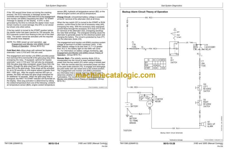
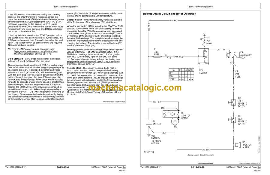
- Backup Alarm Circuit Theory of Operation
- Quik-Tatch Circuit Theory of Operation
- Monitor Operation
- Engagement and Monitor Unit Operation
- Engagement and Monitor Unit Data Items
- Engagement and Monitor Unit Display Messages
- Engagement and Monitor Unit Service Menu Operation
- Engagement and Monitor Unit Initial Configuration
- Anti-Theft Security System Operation—If Equipped
- Anti-Theft Security System Configuration—If Equipped
- Anti-Theft Security System Enable—If Equipped
- References
- Service ADVISOR™ Connection Procedure
- Reading Diagnostic Trouble Codes (DTCs)
- Electrical Component Checks
- Electrical Component Checks
- Electrical Component Specifications
- Solenoid Test
- Solenoid Observable Symptom Check
- Alternator Test
- Controller Area Network (CAN) Circuit Test
- Controller Area Network (CAN) Diagnostics
- Auxiliary Hydraulics Calibration
- Engine Control Unit (ECU) Remove and Install
- Engagement and Monitor Unit (EMU) Remove and Install
- Control Panel Remove and Install
- Backup Alarm Remove and Install
- Battery Remove and Install
- Replace (Pull Type) Metri-Pack™ Connectors
- Replace (Push Type) Metri-Pack™ Connectors
- Replace Metri-Pack™ Connectors
- Replace WEATHER PACKWEATHER PACK is a trademark of Packard Elect
- Install WEATHER PACKWEATHER PACK is a trademark of Packard Elect
- Replace DEUTSCHDEUTSCH is a trademark of Deutsch Co.™ Rectangula
- Replace DEUTSCH DEUTSCH is a trademark of the Deutsch Co.™ Circu
- Replace DEUTSCHDEUTSCH is a trademark of the Deutsch Co.™ Connec
- Install DEUTSCHDEUTSCH is a trademark of the Deutsch Co.™ Contac
- Replace CINCH™ Connectors
- Install CINCH™ Contact
- Repair 32 and 48 Way CINCH™ Connectors
- Remove Connector Body from Blade Terminals
- Power Train
- Theory of Operation
- Power Train System Operation
- Chain Case Operation
- Drive Chain Operation
- Drive Axle Operation
- Diagnostic Information
- Power Train Component Location
- Oil Leak From Power Train
- Oil Leak From Power Train Diagnostic Procedure
- Excessive Axle Play
- Excessive Axle Play Diagnostic Procedure
- Drive Chain Noise
- Drive Chain Noise Diagnostic Procedure
- Grinding Noise
- Grinding Noise Diagnostic Procedure
- One Drive Wheel Not Powered
- One Drive Wheel Not Powered Diagnostic Procedure
- Both Wheels On One Side Not Powered
- Tests
- Drive Chain Tension Check and Adjustment
- Hydraulic System
- Theory of Operation
- Hydraulic System Operation
- Hydraulic Oil Filter Manifold Operation
- High Flow Pump Operation—If Equipped
- Self Leveling Valve Operation—If Equipped
- Hydraulic Pump Operation
- Hydraulic Fan Operation
- Hydraulic Control Valve Operation
- Diagnostic Information
- Hydraulic System Schematic
- Hydraulic System Component Location
- Diagnose Hydraulic System Malfunctions
- No Hydraulic Functions
- No Hydraulic Functions Diagnostic Procedure
- Boom Will Not Raise
- Boom Will Not Raise Diagnostic Procedure
- Boom Will Not Lower
- Boom Will Not Lower Diagnostic Procedure
- Bucket Will Not Dump
- Bucket Will Not Dump Diagnostic Procedure
- Bucket Will Not Curl
- Bucket Will Not Curl Diagnostic Procedure
- Bucket Will Not Self Level When Boom is Raised
- Bucket Will Not Self Level When Boom is Raised Diagnostic Proced
- Bucket Dumps During Self Leveling Cycle
- Bucket Dumps During Self Leveling Cycle Diagnostic Procedure
- Boom Drifts Down
- Boom Drifts Down Diagnostic Procedure
- Boom Drifts Up
- Boom Drifts Up Diagnostic Procedure
- Bucket Drifts Down
- Bucket Drifts Down Diagnostic Procedure
- Bucket Drifts Up
- Bucket Drifts Up Diagnostic Procedure
- Hydraulic Functions Slow or No Power
- Hydraulic Functions Slow or No Power Diagnostic Procedure
- Hydraulic Functions “Jerky” or “Spongy”
- Hydraulic Functions “Jerky” or “Spongy” Diagnostic Procedure
- Hydraulic System Noise
- Hydraulic System Noise Diagnostic Procedure
- Pedals Will Not Move
- Pedals Will Not Move Diagnostic Procedure
- Hydraulic Oil Overheats
- Hydraulic Oil Overheats Diagnostic Procedure
- Hydraulic Fan System Malfunctions
- Hydraulic Fan System Malfunctions Diagnostic Procedure
- Hydraulic Fan Will Not Reverse Direction
- Hydraulic Fan Will Not Reverse Direction Diagnostic Procedure
- Tests
- JT05800 Digital Thermometer Installation
- JT02156A Digital Pressure/Temperature Analyzer Installation
- Remote Start Box Installation
- Hydraulic System Pressure Release
- Boom Release Cable Adjustment
- Pilot Control Accumulator Precharge Test
- Port Lock Solenoid Valve and Port Lock Spool Test
- Boom and Bucket Spool Lock Solenoid Test
- Hydraulic System Relief Valve Test
- Charge Pressure Relief Valve Test
- Circuit Relief Valve Test
- Function Drift Test
- Hydraulic Cylinder Leakage Test
- Hydraulic Pump Flow Test
- Charge Pump Flow Test
- Hydraulic Fan Motor Speed Test
- Hydraulic Fan Motor Case Drain Test
- Fan Bypass Valve Test
- Hydrostatic System
- Theory of Operation
- Hydrostatic System Operation
- Hydrostatic Pump Operation
- Charge Pump Operation
- Hydrostatic Motor Operation—Single Speed
- Hydrostatic Motor Operation—Two Speed
- Hydrostatic Control Valve Operation
- Park Brake System Operation
- Steering Control Operation
- Diagnostic Information
- Hydrostatic System Schematic
- Hydrostatic System Component Location
- Diagnose Hydrostatic System Malfunctions
- Machine Does Not Move In Either Direction
- Machine Does Not Move In Either Direction Diagnostic Procedure
- Hydrostatic Pump Or Hydrostatic Motor Noise
- Hydrostatic Pump Or Hydrostatic Motor Noise Diagnostic Procedure
- Slow Response To Changes In Speed
- Slow Response To Changes In Speed Diagnostic Procedure
- Low Power
- Low Power Diagnostic Procedure
- Wheels Powered On One Side, Not The Other
- Wheels Powered On One Side, Not The Other Diagnostic Procedure
- Machine Will Not Shift Into Or Out Of High Speed
- Machine Will Not Shift Into Or Out Of High Speed Diagnostic Proc
- Machine Creeps With Steering Levers In Neutral
- Machine Creeps With Steering Levers In Neutral Diagnostic Proced
- Hydrostatic System Noise While In Neutral
- Hydrostatic System Noise While In Neutral Diagnostic Procedure
- Steering Levers Hard To Move
- Steering Levers Hard To Move Diagnostic Procedure
- Steering Levers Feel Loose Or “Sloppy”
- Steering Levers Feel Loose Or “Sloppy” Diagnostic Procedure
- Machine Tracks To One Side With Steering Levers In Full Forward
- Machine Tracks To One Side With Steering Levers In Full Forward
- Steering Levers Pulse Or Vibrate Excessively
- Steering Levers Pulse Or Vibrate Excessively Diagnostic Procedur
- Park Brake Does Not Hold
- Park Brake Does Not Hold Diagnostic Procedure
- Park Brakes Do Not Release
- Park Brakes Do Not Release Diagnostic Procedure
- Grinding Noise While Operating Machine
- Grinding Noise While Operating Machine Diagnostic Procedure (Sin
- Tests
- Engine Speed Control for Testing
- Hydrostatic Pump System Pressure Relief Test
- Wheel Speed Test
- Hydrostatic Pump Flow Test
- Centering Plate Adjustment
- Steering Lever Adjustment—Centering
- Tracking Adjustment
- Hydraulic Control Handle Adjustment—Hands Only Machine
- Park Brake Release Pressure Test
- Hydrostatic Motor Case Drain Test
- Heating and Air Conditioning
- Theory of Operation
- Air Conditioning System Cycle of Operation
- Diagnostic Information
- Air Conditioning and Heater System Component Location
- Air Conditioning System Does Not Operate
- Air Conditioning System Does Not Operate Diagnostic Procedure
- Air Conditioning Does Not Cool Interior of Cab
- Air Conditioning Does Not Cool Interior of Cab Diagnostic Proced
- Air Conditioner Runs Constantly, Too Cool
- Air Conditioner Runs Constantly, Too Cool Diagnostic Procedure
- Heater System Does Not Operate
- Heater System Does Not Operate Diagnostic Procedure
- Heater Does Not Warm Interior of Cab
- Heater Does Not Warm Interior of Cab Diagnostic Process
- Interior Windows Continue to Fog
- Interior Windows Continue to Fog Diagnostic Procedure
- Tests
- Refrigerant Cautions and Proper Handling
- Air Conditioner and Heater Operational Checks
- Visual Inspection Of Components
- Refrigerant Leak Testing
- Air Conditioner Compressor Clutch Test
- Air Conditioning High-Low Pressure Switch Test
- Air Conditioner Freeze Control Switch Test
- R134a Refrigerant Cautions
- R134a Oil Charge Capacity
- R134a Refrigerant Charge Capacity
- Operating Pressure Diagnostic Chart
- Dealer Fabricated Tools
- Dealer Fabricated Tools
- DFT1325 Solenoid Power Harness
- Page Number
- Section 9000
- Section 9001
- Section 9005
- Section 9010
- Group 05
- Group 15
- Group 25
- Section 9015
- Group 05
- Group 10
- Group 15
- Group 16
- Group 20
- Section 9020
- Group 05
- Group 15
- Group 25
- Section 9025
- Group 05
- Group 15
- Group 25
- Section 9026
- Group 05
- Group 15
- Group 25
- Section 9031
- Group 05
- Group 15
- Group 25
- Section 9900
John Deere