$ 0
0
$ 0
0

John Deere 803M, 853M, and 859M Tracked Feller Buncher Repair Technical Manual (TM13244X19)

Format: PDF (Printable Document)

File Language: English

File Pages: 408

File Size: 16.01 MB (Speed Download Link)
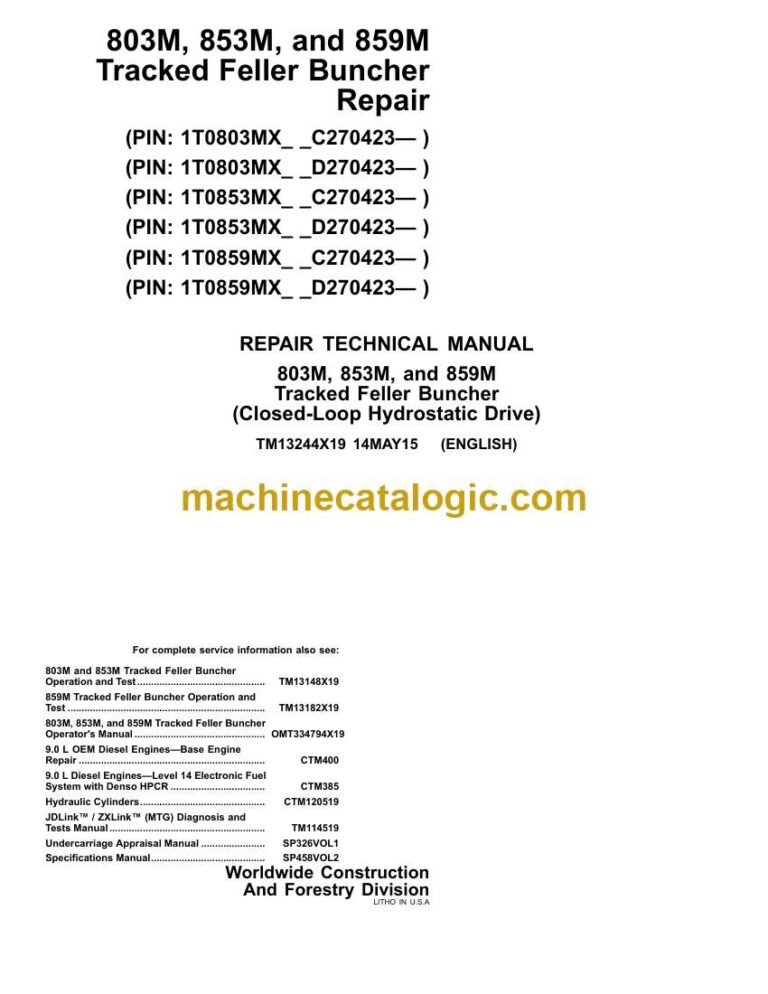
Brand: John Deere

Model: 803M, 853M, and 859M Tracked Feller Buncher

Book No: TM13244X19

Type of Document: Repair Technical Manual

Categories: ,

$ 40

Share:

John Deere 803M, 853M, and 859M Tracked Feller Buncher Repair Technical Manual (TM13244X19)

John Deere 803M, 853M, and 859M Tracked Feller Buncher Repair Technical Manual (TM13244X19)

📘 Show Index

John Deere 803M, 853M, and 859M Tracked Feller Buncher Index:

  • Contents
    • General Information
      • Safety
        • Information for European Union Directives Compliance
        • Recognize Safety Information
        • Follow Safety Instructions
        • Operate Only If Qualified
        • Wear Protective Equipment
        • Avoid Unauthorized Machine Modifications
        • Inspect Machine
        • Stay Clear of Moving Parts
        • Avoid High-Pressure Oils
        • Avoid High-Pressure Fluids
        • Work In Ventilated Area
        • Handle Starting Fluid Safely
        • Prevent Fires
        • In Case of Machine Fire
        • Prevent Battery Explosions
        • Handle Chemical Products Safely
        • Dispose of Waste Properly
        • Prepare for Emergencies
        • Clean Debris from Machine
        • Add Cab Guarding for Special Uses
        • Control Pattern
        • Use Steps and Handholds Correctly
        • Start Only From Operator’s Seat
        • Use and Maintain Seat Belt
        • Avoid Work Site Hazards
        • Prevent Unintended Machine Movement
        • Operate Machine Safely
        • Avoid Machine Tip Over
        • Keep Riders Off Machine
        • Use Care When Swinging Machine
        • Operate Boom With Care
        • Avoid Backover Accidents
        • Operating On Slopes
        • Add and Operate Attachments Safely
        • Travel Safely
        • Avoid Power Lines
        • Inspect and Maintain ROPS
        • Park and Prepare for Service Safely
        • Service Machines Safely
        • Service Cooling System Safely
        • Service Accumulator Systems Safely
        • Remove Paint Before Welding or Heating
        • Make Welding Repairs Safely
        • Drive Metal Pins Safely
      • Torque Values
        • Unified Inch Bolt and Screw Torque Values
        • Metric Bolt and Cap Screw Torque Values
        • Additional Metric Cap Screw Torque Values
        • Check Oil Lines And Fittings
        • Service Recommendations for O-Ring Boss Fittings
        • Service Recommendations For Flat Face O-Ring Seal Fittings
        • Service Recommendations for 37° Flare and 30° Cone Seat Connectors
        • Service Recommendations For Flared Connections—Straight or Tapered Threads
        • Service Recommendations For Inch Series Four Bolt Flange Fittings
        • Service Recommendations for Metric Series Four Bolt Flange Fitting
    • Tracks
      • Track System
        • Measure Track Chain and Roller Wear
        • Track Shoe Remove and Install
        • Track Chain Remove and Install
        • Track Chain Disassemble and Assemble
        • Track Roller Remove and Install
        • Track Carrier Roller Remove and Install
        • Track Carrier Wear Plate Remove and Install
        • Sprocket Remove and Install
        • Front Idler Remove and Install
        • Front Idler Disassemble and Assemble
        • Track Adjuster Cylinder, Recoil Spring, and Yoke Remove and Install
        • Track Adjuster Cylinder Disassemble and Assemble
    • Axles and Suspension Systems
      • Axle Shaft, Bearings, and Reduction Gears
        • Final Drive Remove and Install
        • Final Drive Disassemble
        • Final Drive Assemble
        • Travel Motor Park Brake Disassemble and Assemble
      • Hydraulic System
        • Travel Motor Remove and Install
        • Travel Motor Disassemble and Assemble
    • Transmission
      • Hydraulic System
        • Pump Drive Gear Case Remove and Install
        • Pump Drive Gear Case Disassemble and Assemble
        • Hydrostatic Pump Remove and Install
        • Hydrostatic Pump Disassemble
        • Hydrostatic Pump Assemble
        • Hydrostatic Motor Disassemble
        • Hydrostatic Motor Assemble
        • Charge Pump Remove and Install
        • Charge Pump Disassemble and Assemble
        • Multi-Function Valve Remove and Install
        • Multi-Function Valve Disassemble and Assemble
        • Electric Displacement Control (EDC) Valve Disassemble and Assemble
        • Accumulator Remove and Install
        • Hydrostatic Control Manifold Remove and Install
        • Hydrostatic Flushing Valve Remove and Install
    • Engine
      • Removal and Installation
        • John Deere Engine
        • Engine Identification
        • Engine Remove and Install
    • Engine Auxiliary System
      • Cooling Systems
        • Fan Shroud Remove and Install
        • Belt Remove and Install
        • Cooling Package Remove and Install
        • Cooling Package Disassemble and Assemble
        • Diesel-Fired Coolant Heater Remove and Install
        • Charge Air Cooler Remove and Install
      • Exhaust Systems
        • Muffler Remove and Install
      • Engine Mounts
        • Engine Mounts Remove and Install
      • External Fuel Supply System
        • Fuel Tank Remove and Install
        • Fuel Cooler/Condenser Remove and Install
    • Electrical System
      • Removal and Installation
        • Installation of Repair Wire Assembly (RWA)
        • Electronic Controllers Remove and Install
        • Remove Connector Body from Blade Terminals
        • CINCH™ Connector Remove and Install
        • CINCH™ Contact Installation
        • CINCH™ CP Connector Remove and Install
        • CINCH™ CP Contact Installation
        • DEUTSCH® Connector Remove and Install
        • DEUTSCH® Contact Installation
        • Metri-Pack® Connector Remove and Install
        • WEATHER PACK® Connector Remove and Install
        • WEATHER PACK® Contact Installation
    • Frame or Supporting Structure
      • Frame Installation
        • Welding on Machine
        • RIVNUTRIVNUT is a registered trademark of The BF Goodrich Co.® (KREMNUT) Fasteners Remove and Install
      • Leveler Frames
        • Lower Leveler Frame Remove and Install
        • Upper Leveler Frame Remove and Install
        • Leveler Cylinder Remove and Install
        • Leveler Cylinder Disassemble and Assemble
      • Chassis Weights
        • Counterweight Remove and Install
    • Operator’s Station
      • Removal and Installation
        • Cab Remove and Install
      • Operator Enclosure
        • Window Remove and Install
      • Seat and Seat Belt
        • Seat Remove and Install
        • Seat Belt Remove and Install
      • Heating and Air Conditioning
        • R134a Refrigerant Cautions and Proper Handling
        • R134a Refrigerant Oil Information
        • R134a Refrigerant Recovery, Recycling, and Charging Station Installation Procedure
        • Recover R134a Refrigerant
        • Flush and Purge Air Conditioning System
        • Evacuate R134a System
        • Charge R134a System
        • Compressor Remove and Install
        • Condenser Remove and Install
        • Receiver-Dryer Remove and Install
        • Expansion Valve Remove and Install
        • Freeze Control Switch Remove and Install
        • Freeze Control Switch Bench Test
        • Heater Control Valve Remove and Install
        • Heater Control Valve Leak Check
        • Heater Core and Evaporator Core Remove and Install
        • Blower Motor Remove and Install
    • Sheet Metal and Styling
      • Hood or Engine Enclosure
        • Enclosure Door Pump and Motor Remove and Install
        • Enclosure Door Manifold Remove and Install
        • Enclosure Door Lock Cylinder Remove and Install
        • Enclosure Door Safety Cable Remove and Install
        • Enclosure Door Hydraulic Cylinder Remove and Install
        • Enclosure Door Remove and Install
    • Main Hydraulic System
      • Removal and Installation
        • Main Hydraulic Pump Remove and Install
        • Saw Pump and Attachment Pump Remove and Install
        • Hydraulic Reservoir Remove and Install
        • Main Control Valve Remove and Install
        • Attachment Control Valve Remove and Install
        • Auxiliary Control Valve Remove and Install
        • Hydraulic Fan Motor Remove and Install
        • Attachment Pump Unloading Valve Remove and Install
      • Hydraulic System
        • General Oil Cleanup Procedure
        • Hydraulic Component Failure Cleanup Procedure
        • Main Hydraulic Pump Disassemble and Assemble
        • Saw and Attachment Pumps Disassemble and Assemble
        • Main Control Valve Disassemble and Assemble
        • Pilot Manifold Disassemble and Assemble
        • Attachment Control Valve Disassemble and Assemble
        • Manual Hydraulic Fill Pump Disassemble and Assemble
        • Auxiliary Control Valve Disassemble and Assemble
    • Boom and Stick
      • Frames
        • Boom Remove and Install
        • Stick Remove and Install
        • Boom Guards Remove and Install
        • One Piece Bushing Remove and Install
        • Two Piece Bushing Remove and Install
      • Hydraulic System
        • Boom, Stick, and Tilt Cylinders Remove and Install
        • Boom, Stick, and Tilt Cylinders Disassemble and Assemble
    • Swing or Pivoting System
      • Remove and Install
        • Upperstructure Remove and Install
      • Swing Brake
        • Swing Brake Remove and Install
        • Swing Brake Disassemble and Assemble
      • Swing Drive Gear Case and Bearing
        • Swing Gear Case Remove and Install
        • Swing Gear Case Disassemble and Assemble
        • Swing Bearing Remove and Install
        • Swing Bearing Seal Remove and Install
        • Swing Bearing Pinion Backlash Adjustment
      • Hydraulic System
        • Rotary Manifold Remove and Install
        • Rotary Manifold Remove and Install—Leveler
        • Rotary Manifold Disassemble and Assemble
        • Rotary Manifold Air Test
        • Swing Motor Remove and Install
        • Swing Motor Disassemble and Assemble
        • Swing Motor Crossover Relief Valve Remove and Install
    • Dealer Fabricated Tools
      • Dealer Fabricated Tools
        • DFT1250 Lifting Bracket
        • DFT1324 Pump Support Bracket
        • DFT1041 Track Nut Removal Tool
        • DFT1283 Swing Bearing Adjustment Tool
        • DFT1289 Final Drive Torque Center Drum
        • DFT1290 Final Drive Torque Side Mounting Bracket
        • DFT1291 Final Drive Torque Side Load Spacer
        • DFT1346 Flag Pin Puller
  • Page Number
    • Section 00
      • Group 01
      • Group 0003
    • Section 01
      • Group 0130
    • Section 02
      • Group 0250
      • Group 0260
    • Section 03
      • Group 0360
    • Section 04
      • Group 0400
    • Section 05
      • Group 0510
      • Group 0530
      • Group 0540
      • Group 0560
    • Section 16
      • Group 1600
    • Section 17
      • Group 1740
      • Group 1745
      • Group 1749
    • Section 18
      • Group 1800
      • Group 1810
      • Group 1821
      • Group 1830
    • Section 19
      • Group 1910
    • Section 21
      • Group 2100
      • Group 2160
    • Section 37
      • Group 3740
      • Group 3760
    • Section 43
      • Group 4300
      • Group 4311
      • Group 4350
      • Group 4360
    • Section 99
      • Group 9900

John Deere

Latest Product

0
    0
    Your Cart
    Your cart is emptyReturn to Shop