$ 0
0
$ 0
0

John Deere 318E, 319E, 320E, and 323E Skid Steer and Compact Track Loader Repair Technical Manual (TM13012X19)

Format: PDF (Printable Document)

File Language: English

File Pages: 376

File Size: 14.42 MB (Speed Download Link)

Brand: John Deere

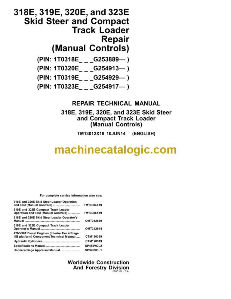
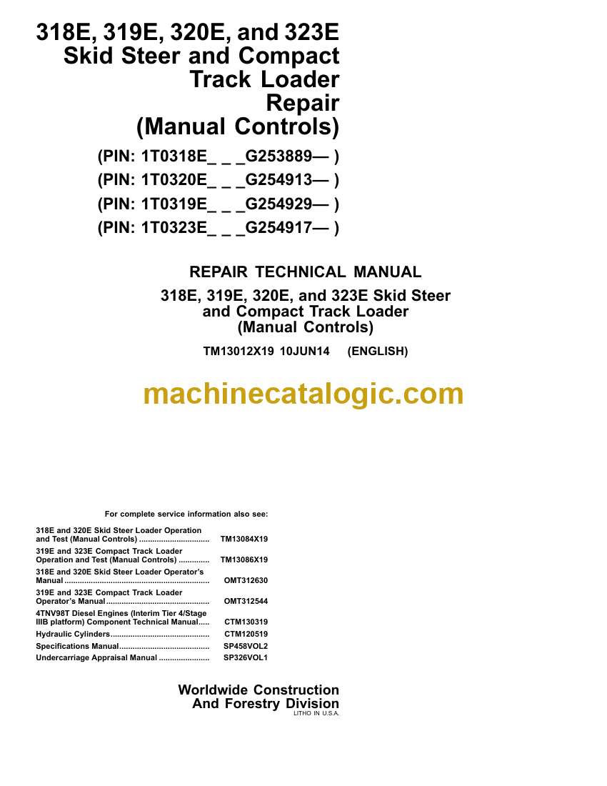
Model: 318E, 319E, 320E, and 323E Skid Steer and Compact Track Loader

Book No: TM13012X19

Type of Document: Repair Technical Manual

Categories: ,

$ 40

Share:

John Deere 318E, 319E, 320E, and 323E Skid Steer and Compact Track Loader Repair Technical Manual (TM13012X19)

John Deere 318E, 319E, 320E, and 323E Skid Steer and Compact Track Loader Repair Technical Manual (TM13012X19)

📘 Show Index

John Deere 318E, 319E, 320E, and 323E Skid Steer and Compact Track Loader Index:

  • Contents
    • General Information
      • Safety
        • Recognize Safety Information
        • Follow Safety Instructions
        • Operate Only If Qualified
        • Wear Protective Equipment
        • Avoid Unauthorized Machine Modifications
        • Inspect Machine
        • Stay Clear of Moving Parts
        • Avoid High-Pressure Fluids
        • Avoid High-Pressure Oils
        • Work In Ventilated Area
        • Avoid Static Electricity Risk When Refueling
        • Prevent Fires
        • Prevent Battery Explosions
        • Handle Chemical Products Safely
        • Dispose of Waste Properly
        • Prepare for Emergencies
        • Clean Debris from Machine
        • Use Steps and Handholds Correctly
        • Start Only From Operator’s Seat
        • Use and Maintain Seat Belt
        • Prevent Unintended Machine Movement
        • Avoid Work Site Hazards
        • Keep Riders Off Machine
        • Avoid Backover Accidents
        • Avoid Machine Tip Over
        • Operating On Slopes
        • Operating or Traveling On Public Roads
        • Inspect and Maintain ROPS
        • Add and Operate Attachments Safely
        • Park and Prepare for Service Safely
        • Service Cooling System Safely
        • Remove Paint Before Welding or Heating
        • Make Welding Repairs Safely
        • Drive Metal Pins Safely
        • Service Tires Safely
        • Handle Cab Door Safely
      • Torque Values
        • Unified Inch Bolt and Cap Screw Torque Values
        • Metric Bolt and Cap Screw Torque Values
        • Additional Metric Cap Screw Torque Values
        • Check Oil Lines And Fittings
        • Service Recommendations for O-Ring Boss Fittings
        • Service Recommendations for 37° Flare and 30° Cone Seat Connectors
        • Service Recommendations For Flared Connections—Straight or Tapered Threads
        • Inch Series Four Bolt Flange Fitting For High Pressure Service Recommendations
        • Service Recommendations For Inch Series Four Bolt Flange Fittings
        • O-Ring Face Seal Fittings With SAE Inch Hex Nut And Stud End For High Pressure Service Recommendations
        • O-Ring Face Seal Fittings With Metric Hex Nut And Stud End For Standard Pressure Service Recommendations
        • O-Ring Face Seal Fittings With Metric Hex Nut And Stud End For High Pressure Service Recommendations
        • Service Recommendations for Metric Series Four Bolt Flange Fitting
    • Wheels (or) Tracks
      • Powered Wheels and Fastenings
        • Wheel Remove and Install
        • Tire Remove and Install
      • Track System
        • Measure Rubber Track Height
        • Track Remove and Install
        • Track Roller Remove and Install
        • Drive Sprocket Remove and Install
        • Front or Rear Idler Remove and Install
        • Front Idler Yoke Assembly Remove and Install
        • Track Adjuster and Recoil Spring Assembly Remove and Install
        • Track Adjuster Recoil Spring Remove and Install
        • Track Adjuster Cylinder Disassemble and Assemble
    • Axles and Suspension Systems
      • Drive Axle Housing and Support
        • Axle Housing Remove and Install
        • Axle Housing Disassemble and Assemble
      • Axle Shaft, Bearings, and Reduction Gears
        • Chain Case Access Plate Remove and Install
        • Drive Chain and Sprocket Remove and Install
    • Transmission
      • Controls Linkage
        • Centering Plate Remove and Install
        • Centering Plate Inspection
        • Steering Damper Remove and Install
        • Steering Damper Inspection
        • Control Lever Remove and Install
        • Control Lever Disassemble and Assemble
        • Control Lever Handle Remove and Install
        • Steering Cross Shaft Assembly Remove and Install
        • Steering Cross Shaft Disassemble and Assemble
      • Flywheel Coupler
        • Hub Coupler Remove and Install
      • Hydraulic System
        • Hydrostatic and Hydraulic Start-Up Procedure
        • Hydrostatic Motor and Park Brake Repair
        • Hydrostatic Motor and Park Brake Remove and Install
        • Hydrostatic Motor and Park Brake Remove and Install—Two Speed
        • Hydrostatic Motor and Park Brake Disassemble and Assemble
        • Hydrostatic Motor and Park Brake Disassemble—Two Speed
        • Hydrostatic Motor and Park Brake Inspection—Two Speed
        • Hydrostatic Motor and Park Brake Assemble—Two Speed
        • Measuring Park Brake Piston Movement—Two Speed
        • Hydrostatic Motor, Park Brake, and Gear Case Repair
        • Hydrostatic Motor, Park Brake, and Gear Case Remove and Install
        • Hydrostatic Motor, Park Brake, and Gear Case Disassemble
        • Hydrostatic Motor, Park Brake, and Gear Case Inspection
        • Hydrostatic Motor, Park Brake, and Gear Case Assemble
        • Inspect Metal Face Seals
        • Gear Case Leakage Test
        • Hydrostatic Pump Remove and Install
        • Hydrostatic Pump Disassemble
        • Hydrostatic Pump Inspection
        • Hydrostatic Pump Assemble
        • Charge Pump Remove and Install
        • Hydrostatic Control Valve Remove and Install
        • Hydrostatic Control Valve Disassemble and Assemble
        • Return Manifold Screen Remove and Install
    • Engine
      • Removal and Installation
        • John Deere Engine
        • Engine Remove and Install
        • Starter Motor Remove and Install
        • Accessory Drive Belt Tensioner Remove and Install
        • Damper Plate Remove and Install
        • Compressor Bracket Remove and Install
        • Engine Oil Dipstick Tube Remove and Install
    • Engine Auxiliary System
      • Cooling Systems
        • Fan Remove and Install
        • Radiator Remove and Install
        • Cooling Package Remove and Install
      • Intake System
        • Air Cleaner Remove and Install
      • External Exhaust Systems
        • Exhaust Tube Remove and Install
      • External Fuel Supply Systems
        • Fuel Tank Remove and Install
        • Low-Pressure Fuel Pump Remove and Install
        • Primary Fuel Filter and Water Separator Assembly Remove and Install
        • Final Fuel Filter Assembly Remove and Install
    • Frame or Supporting Structure
      • Frame Installation
        • Welding On Machine
        • Welding Repair of Major Structure
        • Counterweight Remove and Install
        • Raising and Blocking Machine
    • Operator’s Station
      • Removal and Installation
        • Operator’s Station Remove and Install
      • Operator Enclosure
        • Cab Door Remove and Install
        • Top Window Remove and Install
        • Rear Window Remove and Install
        • Side Window Remove and Install
        • Raising Operator’s Station
      • Seat and Seat Belt
        • Seat Remove and Install
        • Seat Belt Remove and Install
        • Interlocking Seat Bar Remove and Install
        • Seat Air Spring Remove and Install
      • Heating and Air Conditioning
        • Refrigerant Cautions and Proper Handling
        • Flush and Purge Air Conditioner System
        • R134a Refrigerant Oil Information
        • R134a Refrigerant Recovery, Recycling, and Charging Station Installation Procedure
        • Recover R134a Refrigerant
        • Evacuate R134a System
        • Charge R134a System
        • Air Conditioner Compressor Remove and Install
        • Expansion Valve Remove and Install
        • Receiver-Dryer Remove and Install
        • Condenser Remove and Install
        • Air Conditioner and Heater Remove and Install
        • Evaporator Remove and Install
        • Blower Fan Remove and Install
        • Heater Core Remove and Install
    • Sheet Metal and Styling
      • Hood or Engine Enclosure
        • Footwell Remove and Install
        • Side Panel Remove and Install
        • Engine Cover Remove and Install
    • Safety and Convenience
      • Radio
        • Radio Antenna Remove and Install
    • Main Hydraulic System
      • Hydraulic System
        • General Oil Cleanup Procedure
        • Hydraulic/Hydrostatic Component Failure Cleanup Procedure
        • Vacuum Pump Installation
        • Hydraulic Fan Motor Remove and Install
        • Hydraulic Oil Cooler Remove and Install
        • Hydraulic Oil Reservoir Remove and Install
        • Hydraulic Pump Remove and Install
        • Hydraulic Pump Disassemble and Assemble
        • High Flow Hydraulic Pump Disassemble and Assemble
    • Loader
      • Attachment Coupler
        • Quik-Tatch™ Coupler Remove and Install
        • Quik-Tatch™ Actuator Remove and Install
      • Control Linkage
        • Pedal Assembly Remove and Install
        • Pedal Assembly Disassemble and Assemble
        • Hand Control Linkage Remove and Install
      • Frame
        • Upper Boom Link Remove and Install
        • Lower Boom Link Remove and Install
        • Boom Remove and Install
        • Boom Lock Remove and Install
        • Boom Lock Disassemble and Assemble
        • Boom Lock
      • Hydraulic System
        • Control Valve Remove and Install
        • Control Valve Disassemble and Assemble
        • Self Leveling Valve Remove and Install
        • Ride Control Accumulator Remove and Install
        • Ride Control Valve Remove and Install
        • Ride Control Valve Disassemble and Assemble
        • Boom Cylinder Remove and Install
        • Bucket Cylinder Remove and Install
        • Hydraulic Cylinder Disassemble and Assemble
        • Hydraulic Oil Filter Manifold Remove and Install
        • Hydraulic Cylinder Bleed Procedure
    • Dealer Fabricated Tools
      • Dealer Fabricated Tools
        • DFT1101 Boom Lifting Bracket
        • ST4920 Track Recoil Spring Disassembly and Assembly Tool
        • DFT1087 Track Recoil Spring Disassembly and Assembly Guard Tool
        • DFT1325 Solenoid Power Harness
        • DFT1333 Lock Nut Wrench
        • DFT1334 Gear Case Turning Tool
        • DFT1335 Park Brake Spring Compressor
        • DFT1336 Bias Spring Compressor
        • DFT1358 Engine Lifting Bracket
        • DFT1359 Engine Lifting Bracket
        • JT38077 Boom Pin Driver
  • Page Number
    • Section 00
      • Group 0001
      • Group 0003
    • Section 01
      • Group 0110
      • Group 0130
    • Section 02
      • Group 0201
      • Group 0250
    • Section 03
      • Group 0315
      • Group 0325
      • Group 0360
    • Section 04
      • Group 0400
    • Section 05
      • Group 0510
      • Group 0520
      • Group 0530
      • Group 0560
    • Section 17
      • Group 1740
    • Section 18
      • Group 1800
      • Group 1810
      • Group 1821
      • Group 1830
    • Section 19
      • Group 1910
    • Section 20
      • Group 2001
    • Section 21
      • Group 2160
    • Section 31
      • Group 3104
      • Group 3115
      • Group 3140
      • Group 3160
    • Section 99
      • Group 9900

John Deere

Latest Product

0
    0
    Your Cart
    Your cart is emptyReturn to Shop