$ 0
0
$ 0
0

John Deere 540E, 640E and 740E Skidder 548E, 648E and 748E Grapple Skidder Repair Technical Manual (TM1486)

Format: PDF (Printable Document)

File Language: English

File Pages: 904

File Size: 14.38 MB (Speed Download Link)
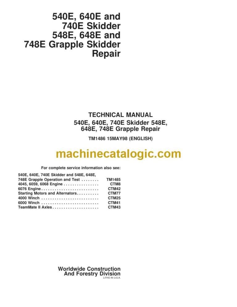
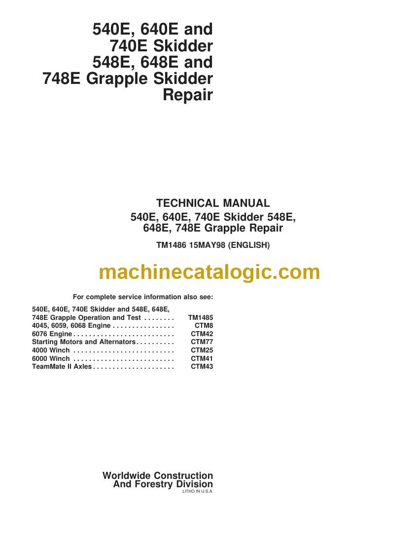
Brand: John Deere

Model: 540E, 640E and 740E Skidder 548E, 648E and 748E Grapple Skidder

Book No: TM1486

Type of Document: Repair Technical Manual

Categories: ,

$ 40

Share:

John Deere 540E, 640E and 740E Skidder 548E, 648E and 748E Grapple Skidder Repair Technical Manual (TM1486)

John Deere 540E, 640E and 740E Skidder 548E, 648E and 748E Grapple Skidder Repair Technical Manual (TM1486)

📘 Show Index

John Deere 540E, 640E and 740E Skidder 548E, 648E and 748E Grapple Skidder Index:

  • Contents
    • General Information
      • Safety
        • Handle Fluids Safely—Avoid Fires
        • Prevent Battery Explosions
        • Prepare for Emergencies
        • Prevent Acid Burns
        • Handle Chemical Products Safely
        • Avoid High-Pressure Fluids
        • Park Machine Safely
        • Support Machine Properly
        • Wear Protective Clothing
        • Work in Clean Area
        • Service Machines Safely
        • Work In Ventilated Area
        • Illuminate Work Area Safely
        • Replace Safety Signs
        • Use Proper Lifting Equipment
        • Remove Paint Before Welding or Heating
        • Avoid Heating Near Pressurized Fluid Lines
        • Keep ROPS Installed Properly
        • Service Tires Safely
        • Avoid Harmful Asbestos Dust
        • Practice Safe Maintenance
        • Use Proper Tools
        • Dispose of Waste Properly
        • Live With Safety
      • General Specifications
        • 540E Skidder
        • 540E Skidder
          • (SN —538545)
          • (SN 538546—)
        • 540E Skidder
        • Winch—4000 Series—540E Skidder
        • 540E Skidder
          • Capacities—(SN —538545)
          • Capacities—(SN 538546—)
        • 548E Grapple Skidder—Dimensions
        • 548E Grapple Skidder
          • (SN —538545)
          • (SN 538546—)
        • 548E Grapple Skidder
        • 548E Grapple Skidder
          • Capacities—(SN —538545)
          • Capacities—(SN 538546—)
        • 640E Skidder
        • Winch—6000 Series
        • Winch—4000 Series
        • 640E Skidder
          • Capacities
        • 648E Grapple Skidder
        • 648E Grapple Skidder
          • Capacities
        • 740E Skidder
        • Winch—6000 Series
        • 740E Skidder
          • Capacities
        • 748E Grapple Skidder
        • 748E Grapple Skidder
          • Capacities
      • Torque Value
        • Hardware Torque Specifications
        • ROPS Torque Specifications
        • Tighten Upper Frame Pivot Pin
        • Metric Bolt and Cap Screw Torque Values
        • Unified Inch Bolt And Cap Screw Torque Values
        • Additional Metric Cap Screw Torque Values
        • Check Oil Lines And Fittings
        • Service Recommendations For 37° Flare And 30° Cone Seat Connectors
        • Service Recommendations for O-Ring Boss Fittings
        • Service Recommendations for Flat Face O-Ring Seal Fittings
        • Service Recommendations For Flared Connections—Straight Or Tapered Threads
        • Service Recommendations For Inch Series Four Bolt Flange Fittings
        • Service Recommendations for Metric Series Four Bolt Flange Fitting
      • Fuels And Lubricants
        • Diesel Fuel
        • Low Sulfur Diesel Fuel Conditioner
        • Storing Fuel
        • Do Not Use Galvanized Containers
        • Fuel Tank
        • Diesel Engine Oil
        • Hydraulic System, Transmission, Park Brake, Differential, And Winch Oils
        • Grease
        • Lubricant Storage
        • Alternative And Synthetic Lubricants
        • Mixing Of Lubricants
        • Diesel Engine Coolant
    • Wheels
      • Powered Wheels And Fastenings
        • Service Equipment And Tools
        • Other Material
        • Specifications
        • Remove And Install Wheel
        • Remove And Install Tire
    • Axles And Suspension System
      • Removal And Installation
        • John Deere 1200 TeamMate™ II Series Axles—Use CTM43
        • Service Equipment And Tools
        • Specifications
        • Remove Front Axle And Differential
        • Disassemble And Assemble Rear Oscillating Support
        • Disassemble And Assemble Front Oscillating Support
        • Install Front Axle And Differential
        • Remove And Install Rear Axle And Differential Assembly
        • Remove And Install Front Axle Guards
      • Input Drive Shafts And U-Joints
        • Specifications
        • Remove And Install Front Differential Drive Shaft
        • Remove And Install Rear Differential And Transmission Drive Shafts
      • Hydraulic System
        • Differential Lock Solenoid Valve
        • Remove And Install Differential Lock Solenoid Valve
        • Differential Lock Relief Valve Cross Section
        • Remove And Install Differential Lock Relief Valve
        • Differential Lock Plumbing
        • Front Differential Plumbing
        • Rear Differential Plumbing
    • Transmission
      • Removal And Installation
        • Service Equipment And Tools
        • Other Material
        • Specifications
        • Remove Transmission
        • Install Transmission
        • Exploded View Of Transmission Case
      • Control Linkage
        • Other Material
        • Specifications
        • Transmission Console Linkage
          • Remove and Install (SN —535530)
          • Remove and Install (SN 535531—)
        • Transmission Control And Park Brake Lever Adjustment
        • Adjust Park Brake Switch
        • Transmission Control Valve Linkage
          • Remove and Install (SN —535530)
          • Remove and Install (SN 535531—)
        • Transmission Control Valve Linkage Adjustment
        • Remove And Install Clutch And Brake Valve Linkage
        • Clutch Linkage Adjustment
        • Brake Pedal Adjustment
      • Input Drive Shafts And U-Joints
        • Other Material
        • Specifications
        • Remove And Install Engine To Transmission Drive Shaft
      • Gears, Shafts And Bearings
        • Service Equipment And Tools
        • Other Material
        • Specifications
        • Cross Section Of C1 And C2 Clutch Pack Assembly
        • Exploded View C1 And C2 Clutch Pack Assembly
        • Exploded View Of Oil Manifold Assembly
        • Remove And Install Oil Manifold, C1 And C2 Clutch Pack Assembly
        • Disassemble Oil Manifold, C1 And C2 Clutch Pack Assembly
        • Remove And Install Transmission Front Cover
        • Cross Section Of C1 And C2 Clutch Pack Assembly And Oil Manifold
        • Exploded View C1 And C2 Clutch Pack Assembly
        • Exploded View Oil Manifold Assembly
        • Assemble Oil Manifold, C1 And C2 Clutch Pack Assembly
        • Disassemble And Assemble High And Low Range Clutch Shaft
        • Complete Park Brake Assembly
        • Cross Section Park Brake
        • Remove And Install Park Brake
        • Remove Reduction Gear And Shaft
        • Inspect Reduction Gear And Shaft Assembly
        • Cross Section Planetary Assembly
        • Exploded View Planetary Assembly
        • Remove And Disassemble Planetary Pack Assembly
        • Assemble And Install Planetary Pack Assembly
        • Remove And Install Idler And Winch Drive Gears
        • Remove And Install Output Gear Assembly
        • Exploded View Of Pump Drive Gears
        • Remove And Install Pump Idler Gear
        • Remove And Install Small Hydraulic Pump Adaptor
        • Remove And Install Pump Drive Gear
        • Install Planetary Assembly
      • Hydraulic System
        • Essential Tools
        • Service Equipment And Tools
        • Specifications
        • Pressure Regulating Valve Oil Passage Identification
        • Transmission Control Valve Oil Passage Identification
        • C1—C2 Clutch Pack And Front Cover Oil Passage Identification
        • Remove Transmission Control Valve Assembly
        • Disassemble Shift Valve
        • Disassemble Control Valve Cover And Valves
        • Disassemble B1-B2 And B3-B4-C3 Accumulators
        • Assemble B1-B2 And B3-B4-C3 Accumulators
        • Assemble Control Valve Cover And Valves
        • Assemble Shift Valve
        • Remove And Install Engagement Override Valve And Interrupter Valve
        • Install Transmission Control Valve Assembly
        • Remove Park Brake Sensor Valve
        • Disassemble And Inspect Park Brake Sensor Valve
        • Install Park Brake Sensor Valve
        • Remove And Install Clutch Valve And Pressure Regulating Valve
        • Disassemble And Reassemble Pressure Regulating Valve
        • Disassemble Transmission Clutch Valve
        • Remove And Install Transmission Screen
        • Remove Transmission Hydraulic Pump And Park Brake Pump
        • Disassemble And Assemble Transmission Hydraulic Pump
        • Install Transmission Hydraulic Pump And Park Brake Pump
        • Remove And Install Park Brake Pump
        • Disassemble And Assemble Transmission Oil Filter And Base
        • Park Brake Sensor Valve Bleeding Procedure
    • Engine
      • Removal And Installation
        • 4045, 6059 And 6068 John Deere Engine—Use CTM8
        • 6076 Engine Repair
          • (SN —499999)
          • (SN —499999)
        • Special Or Essential Tools
        • Service Equipment And Tools
        • Other Material
        • Specifications
        • Disconnect Turbocharger Oil Inlet Line
        • Remove And Install Engine—540E, 548E, 640E, 648E
        • Remove And Install Engine—740E, 748E
        • Remove And Install Oil Pan And Oil Pump
        • Remove Oil Pan
        • Remove Engine Oil Pump
        • Install Engine Oil Pump
        • Install Oil Pan
        • Remove Stanadyne Model DB2 (With Retained Drive Shaft) And DB4 Injection Pump
        • Inspect Injection Pump Drive Gear I.D. And Shaft O.D.
        • Install Stanadyne Model DB2 (With Retained Drive Shaft) And DB4 Injection Pump
        • JT07158 TIME TRAC® Installation
        • Injection Pump Timing
        • Remove In-Line Fuel Injection Pump
        • Install In-Line Fuel Injection Pump
        • Bleed The Fuel System—540E, 548E, 640E, 648E
        • Bleed Fuel System—740E, 748E
        • Remove Fuel Injection Nozzles—540E, 548E, 640E, 648E
        • Install Fuel Injection Lines And Nozzles—540E, 548E, 640E, 648E
        • Remove Fuel Injection Nozzle—740E, 748E
        • Inspect And Clean Cylinder Head Nozzle Bore
        • Install Fuel Injection Nozzle—740E, 748E
        • Remove And Install Intake Manifold—540E, 548E, 640E, 648E
        • Remove And Install Intake Manifold—740E, 748E
        • Remove And Install Turbocharger—540E, 548E, 640E, 648E
        • Remove And Install Turbocharger—740E, 748E
        • Remove And Install Water Pump—540E, 548E, 640E, 648E
        • Remove And Install Water Pump—740E, 748E
        • Remove And Install Thermostats—540E, 548E, 640E, 648E
        • Remove And Install Thermostat Housing—540E, 548E, 640E, 648E
        • Remove And Install Thermostats—740E, 748E
        • Remove And Install Engine Oil Cooler—540E, 548E, 640E, 648E
        • Remove And Install Oil Cooler—740E, 748E
        • Remove And Install Fuel Filter And Base—540E, 548E, 640E, 648E
        • Disassemble And Assemble Primary Fuel Filter (Water Separator)—(SN 536594—)
        • Remove And Install Fuel Filter And Base—740E, 748E
        • Remove And Install Fuel Transfer Pump—540E, 548E, 640E, 648E
        • Remove And Install Fuel Transfer Pump—740E, 748E
    • Engine Auxiliary Systems
      • Cold Weather Starting Aids
        • Other Material
        • Specifications
        • Remove And Install Starting Aid Solenoid And Nozzle—If Equipped
        • Remove And Install Engine Coolant Heater
      • Cooling Systems
        • Specifications
        • Remove And Install Fan Guards And Fan
        • Remove And Install Fan Belts
        • Check and Adjust Fan Belt Tension
        • Remove And Install Fan Shroud
        • Remove And Install Radiator
      • Speed Controls
        • Other Material
        • Specifications
        • Remove And Install Speed Control Linkage—540E, 548E, 640E, 648E
        • Remove And Install Speed Control Linkage—740E, 748E
        • Remove And Install Engine Shut-Off Cable—740E, 748E
        • Engine Speed Control Linkage Adjustment—540E, 548E, 640E, And 648E
        • Engine Speed Control Linkage Adjustment—740E, And 748E
        • Fuel Shut-Off Cable Adjustment—740E And 748E
      • Intake System
        • Essential Tools
        • Service Equipment And Tools
        • Other Material
        • Specifications
        • Remove And Install Air Cleaner—540E, 548E (SN —539529)
        • Remove And Install Air Cleaner—540E, 548E (SN 539530—), 640E, 648E
        • Remove And Install Air Cleaner—740E, 748E (SN —536537)
        • Remove And Install Air Cleaner—740E, 748E (SN 536538—)
        • Remove And Install Air Filter Elements
        • Air Intake System Leakage Test
      • External Exhaust System
        • Remove And Install Muffler—540E, 548E, 640E, 648E
        • Remove And Install Muffler—740E, 748E
      • External Fuel Supply System
        • Essential Tools
        • Service Equipment And Tools
        • Specifications
        • Remove And Install Fuel Tank—540E, 548E, 640E
        • Remove And Install Fuel Tank—648E, 740E And 748E
        • Remove And Install Fuel Gauge Sender
        • Remove And Install Water Separator (If Equipped)
        • Disassemble And Assemble Water Separator (If Equipped)
        • Remove Primary Fuel Filter (Water Separator)
        • Disassemble, Clean And Assemble Water Separator
    • Damper Drive
      • Elements
        • Special Or Essential Tools
        • Other Material
        • Specifications
        • Remove And Install Damper
        • Remove And Install Transmission Disconnect Linkage—If Equipped
        • Transmission Disconnect Linkage Adjustment—If Equipped
        • Disassemble And Assemble Transmission Disconnect Linkage—If Equipped
        • Assemble And Install Transmission Disconnect—If Equipped
    • Steering System
      • Secondary Steering
        • Remove And Install Secondary Steering Pump (SN —550057)
        • Remove And Install Secondary Steering Pump (SN 550058—)
      • Hydraulic System
        • Service Equipment And Tools
        • Specifications
        • Remove Steering Valve
        • Disassemble Steering Valve
        • Cross Section Of Steering Valve
        • Assemble Steering Valve
        • Install Steering Valve
        • Disassemble And Assemble Steering Priority Valve
        • Remove And Install Steering Cylinder
        • Cross Section Of Steering Cylinder
        • Disassemble And Inspect Steering Cylinder
        • Assemble Steering Cylinder
    • Service Brakes
      • Active Elements
        • Brake Lining Inspection
      • Controls Linkage
        • Remove And Install Clutch And Brake Valve Linkage
      • Hydraulic System
        • Remove And Install Brake Valve
        • Disassemble And Assemble Brake Valve
        • Service Brake Hydraulic Bleeding Procedure
        • Brake Pedal Adjustment
        • Remove And Install Accumulator
    • Park Brake
      • Active Elements
        • Complete Park Brake Assembly
        • Assembled Park Brake
      • Hydraulic System
        • Park Brake Solenoid
        • Remove And Install Park Brake Solenoid
        • Park Brake Relief Valve Cross Section
        • Remove And Install Park Brake Relief Valve
        • Park Brake Sensor Valve Bleeding Procedure
        • Clean Or Replace Park Brake/Differential Lock Valve Filter
    • Electrical System
      • Batteries, Support And Cables
        • Service Equipment And Tools
        • Specifications
        • Service Batteries Carefully
        • Check Battery Electrolyte Level And Terminals
        • Using Battery Charger
        • Procedure For Testing Batteries
        • Using Booster Batteries—12 Volt System
        • Remove And Install Batteries
      • Alternator, Regulator And Charging System Wiring
        • John Deere Alternator And Starting Motors Repair—Use CTM-77
        • Service Equipment And Tools
        • Specifications
        • Remove And Install Alternator—78 Amp Delco Remy
        • Remove And Install Alternator—130 Amp Delco Remy
        • Remove And Install Alternator—95 Amp Bosch
        • Remove And Install Alternator—135 Amp Bosch
        • Fan And Alternator Belts Tension Or Replacement
      • Lighting System
        • Remove And Install Lights
        • Remove And Install Light Switch
        • Replace Halogen Bulbs
      • Wiring Harness And Switches
        • Special Or Essential Tools
        • Specifications
        • Remove And Install Indicator Switches
        • Remove Relays, Fuses And Circuit Breakers
        • Remove Blade Terminals From Fuse Block
        • Remove And Install Start Relay And Accessory Relay
        • Remove And Install Wiper Switch
        • Remove And Install Neutral Start Switch And Reverse Warning Alarm Switch
        • Remove And Install Horn Switch, Key Switch And Start Aid Switch
        • Remove And Install Heater Fan Switch
        • Remove And Install Secondary Steering Switch—If Equipped
        • Remove And Install Light Switch
        • Remove And Install Transmission Control And Park Brake Lever Switch
        • Adjust Park Brake Lever Switch
        • Remove And Install Battery Disconnect Switch
        • Replace DEUTSCH™ Connectors
        • Install DEUTSCH™ Contact
        • Replace WEATHER PACK™ Connector
        • Replace SURE-SEAL® Connector With WEATHER PACK™ Connector
        • Install WEATHER PACK™ Contact
        • Remove Connector Body From Blade Terminals
      • Instruments And Indicators
        • Other Material
        • Specifications
        • Remove And Install Engine Coolant Temperature Sender And Engine Oil Pressure Switch—540E, 548E, 640E, 648E (SN —535861)
        • Remove And Install Engine Coolant Temperature Sender And Engine Oil Pressure Switch—540E, 548E, 640E, 648E (SN 535862—)
        • Remove And Install Air Filter Restriction Switch And Engine Coolant Temperature Switch—540E, 548E, 640E, 648E
        • Remove And Install Air Filter Restriction Switch And Engine Oil Pressure Switch—740E, 748E
        • Remove And Install Engine Coolant Temperature Sender And Engine Coolant Temperature Switch—740E, 748E
        • Remove And Install Hydraulic Oil Filter Restriction Switch And Hydraulic Oil Temperature Switch (SN 539007—)
        • Remove And Install Differential Lock Switch
        • Remove And Install Grapple Rotate Switch—(Single Function Only—SN 547883—)
        • Remove And Install Park Brake Pressure Switch, Transmission Oil Pressure Switch, Transmission Oil Temperature Switch And Transmission Oil Filter Restriction Switch (SN —540024)
        • Remove And Install Park Brake Pressure Switch, Transmission Oil Pressure Switch, Transmission Oil Temperature Switch And Transmission Oil Filter Restriction Switch (SN 540025—)
        • Remove And Install Service Brake Pressure Switch
        • Indicator—Top Row Circuit Specifications
        • Indicator—Middle Row Circuit Specifications
        • Indicator—Bottom Row Circuit Specifications
        • Remove And Install Hour Meter
        • Remove And Install Engine Coolant Temperature Gauge And Fuel Gauge
        • Remove And Install Fuel Level Sender
        • Gauges And Hour Meter Circuit Specifications
        • Remove And Install Display Module
        • Remove And Install Monitor Lights
      • Motors And Actuators
        • John Deere Alternator And Starting Motors Repair—Use CTM-77
        • Specifications
        • Remove And Install Starting Motor
    • Frame, Chassis, Or Supporting Structures
      • Frame Installation
        • Service Equipment And Tools
        • Other Material
        • Specifications
        • Welding Repair Of Major Structure
        • Separate Engine And Equipment Frames
        • Remove And Install Frame Pivot Pins
        • Remove And Install Lower Pivot Pin Seals
        • Remove And Install Upper Pivot Bearing And Seals
        • Remove Lower Pivot Pin Spherical Bushing
        • Install Lower Pivot Pin Spherical Bushing
      • Frame Bottom Guards
        • Specifications
        • Remove And Install Engine Frame Front Bottom Guard
        • Remove And Install Equipment Frame Bottom Guards—(SN —550651)
        • Remove And Install Equipment Frame Bottom Guards—(SN 550652— )
    • Operator’s Station
      • Removal And Installation
        • Service Equipment And Tools
        • Specifications
        • Remove And Install Cab Or Canopy—(SN —547882)
        • Remove And Install Cab Isolators
        • Remove And Install Steering Column
      • Operator Enclosure
        • Special Or Essential Tools
        • Other Material
        • Specifications
        • Remove And Install Windowpane And Molding
        • Clean Windows Regularly
        • Remove And Install Cab Door And Adjust Latch
        • Remove And Install Windshield Wiper And Washer
        • Adjust Windshield Wiper And Washer
        • Exploded View Of Defrost Fan—If Equipped
      • Seat And Seat Belt
        • Specifications
        • Disassemble And Assemble Suspension Seat
        • Seat Belt
        • Install Seat Belt Assembly (Right Side)
        • Install Seat Belt Assembly (Left Side)
      • Heating And Air Conditioning
        • Special Or Essential Tools
        • Service Equipment And Tools
        • Other Material
        • Service Parts Kits For Compressor
        • Specifications
        • Proper Refrigerant Handling
        • R12 And R134A Refrigerant Cautions
        • R12 Component Oil Charge
        • R12 Refrigerant Evacuation And Charging Station Installation Procedure
        • Recover R12 System
        • Evacuate R12 System
        • Charge R12 System
        • R134A Compressor Oil Information
        • R134A Compressor Oil Charge Check
        • R134A Component Oil Charge
        • R134A Compressor Oil Removal
        • R134A Refrigerant Recovery, Recycling And Charging Station Installation Procedure
        • Recover R134A System
        • Evacuate R134A System
        • Charge R134A System
        • Leak Testing
        • Check And Adjust Compressor Belt Tension
        • Remove And Install Compressor
        • Volumetric Efficiency Test—R12
        • Shaft Seal Leak Test
        • Disassemble And Inspect Compressor
        • Clutch Pulley, Bearing And Hub Inspection
        • Replacing Clutch Pulley Bearing
        • Replace Shaft Seal Seat
        • Assemble Compressor
        • Remove And Install Condenser
        • Remove And Install Evaporator And Expansion Valve
        • Remove And Install Receiver Dryer
        • Remove And Install Condenser Fan Motors
        • Freeze Control Temperature Cycling Switch
        • Disassemble And Assemble Blower Motor
        • Remove And Install Heater—If Equipped
        • Remove And Install Heater Core
        • Air Conditioning Component Location
    • Sheet Metal And Styling
      • Hood Or Engine Enclosure
        • Essential Tools
        • Specifications
        • Remove And Install Hood
      • Grille And Grille Housing
        • Specifications
        • Remove And Install Grille And Grille Housing
    • Safety, Convenience And Miscellaneous
      • Horn And Warning Devices
        • Specifications
        • Remove And Install Horn
        • Remove And Install Reverse Warning Alarm
        • Adjust Reverse Warning Alarm Volume—If Equipped
        • Inspect Fire Extinguisher
    • Main Hydraulic System
      • Hydraulic System
        • Specifications
        • Remove And Install Hydraulic Pump
        • Hydraulic Pump Cross Section—(SN —538966)
        • Hydraulic Pump Cross Section—(SN 538967—)
        • Disassemble And Inspect Hydraulic Pump
        • Assemble Hydraulic Pump
        • Disassemble And Assemble Steering Priority Valve
        • Remove And Install Hydraulic Oil Filter
        • Remove And Install Hydraulic Reservoir
        • Hydraulic Oil Cleanup Procedure Using Portable Filter Caddy
    • Winch
      • Removal And Installation
        • John Deere 4000 Winch Repair—Use CTM25
        • John Deere 6000 Winch Repair—Use CTM41
        • Other Material
        • Specifications
        • Remove Winch—4000 Series
        • Install Winch—4000 Series
        • Install Winch Drum Plug—4000 Series
        • Fasten Cable To Winch Drum—4000 Series
        • Winch Freespool Drag Adjustment
        • Remove 6000 Series Winch
        • Install 6000 Series Winch
        • Fasten Cable To Drum—6000 Series Winch
      • Controls Linkage
        • Remove And Install Winch Control Valve Linkage
        • Remove And Install Winch Control Valve
        • Winch Control Valve Checks
        • (Başlıksız)
        • (Başlıksız)
        • (Başlıksız)
        • (Başlıksız)
        • Disassemble And Assemble Winch Control Valve
        • Remove And Install Winch Control Cable
      • Input Drive Shafts And U-Joints
        • Other Material
        • Specifications
        • Remove And Install Winch Drive Line
        • Disassemble And Assemble Winch Drive Shaft
      • Drive And Clutch
        • John Deere 4000 Winch Repair—Use CTM25
        • John Deere 6000 Winch Repair—Use CTM41
    • Bulldozers (Stacking And Trailbuilding Blades)
      • Blades
        • Service Equipment And Tools
        • Other Material
        • Specifications
        • Remove And Install Stacking Blade
        • Remove Spherical Bushing
        • Install Spherical Bushing
      • Controls Linkage
        • Other Material
        • Remove And Install Control Linkage—Blade
        • Remove And Install Blade Control Valve Support—(SN —547882)
        • Remove And Install Blade Control Valve Support—(SN 547883—)
      • Hydraulic System
        • Blade Control Valve
        • Blade Cylinder
        • Remove And Install Blade Lift Cylinder
    • Arch Or Boom
      • Frames
        • Service Equipment And Tools
        • Specifications
        • Remove And Install Log Arch
        • Remove And Install Horizontal Roller
        • Remove Side Roller
        • Install Side Roller
        • Remove And Install Roller Brackets
    • Grapple
      • Grapple Mechanism
        • Twin Cylinder John Deere Grapples—(SN 547978, 547979, 548024, 548025, 548164, 548165, 549773, 549774, 549872, 549873)
        • Service Equipment And Tools
        • Specifications
        • Other Material
        • Exploded View Of Grapple Crosshead Dampers And Pins
        • Remove And Install Grapple
        • Remove And Install Grapple Bulkhead Hoses
        • Disassemble And Assemble Grapple Assembly
        • Disassemble And Assemble Grapple Pivot
        • Remove And Install Bushings
        • Remove, Install, And Adjust Grapple Dampers
      • Controls Linkage
        • Other Material
        • Remove And Install Control Linkage—Single Function Grapple (SN —547882)
        • Single Function Grapple Control Linkage (SN 547883—)
        • Remove And Install Control Linkage—Dual Function Grapple (SN —547882)
        • Dual Function Grapple Control Linkage (SN 547883—)
      • Frames
        • Service Equipment And Tools
        • Specifications
        • Remove And Install Rollers For Fairlead
        • Remove And Install Boom—Single Function Grapple
        • Remove And Install Boom—Dual Function Grapple
        • Remove And Install Dual Function Arch
        • Remove Spherical Bushing
        • Install Spherical Bushing
      • Hydraulic System
        • Service Equipment And Tools
        • Other Material
        • Specifications
        • Remove And Install Control Valve—Single Function Grapple (SN —547882)
        • Remove And Install Control Valve—Single Function Grapple (SN 547883—)
        • Disassemble And Assemble Single Function Control Valve (SN —547882)
        • Remove And Install Control Valve—Dual Function Grapple (SN —547882)
        • Remove And Install Control Valve—Dual Function Grapple (SN 547883—)
        • Disassemble And Assemble Dual Function Control Valve (SN 547883—)
        • Remove And Install Circuit Relief Valves, Lift Check Poppets, And Lockout Check Plugs (SN —547882)
        • Disassemble Grapple And Blade Control Valves (SN —547882)
        • Cross Section Of Rotate Valve (SN —547882)
        • Cross Section Of Grapple Valve (SN —547882)
        • Cross Section Of Boom And Blade Valve (SN —547882)
        • Assemble Grapple And Blade Control Valve (SN —547882)
        • Remove Rotate Motor
        • Remove, Disassemble, Assemble And Install Crossover Relief Valve
        • Disassemble Rotate Motor
        • Assemble Rotate Motor
        • Remove And Install Rotate Motor Drive Gear
        • Install Rotate Motor
        • Remove And Install Boom Cylinder—Single Function Grapple
        • Remove And Install Boom Or Arch Cylinder—Dual Function Grapple
        • Remove And Install Grapple Cylinder
        • Cross Section Of Boom, Arch, And Single Function Grapple Cylinder
        • Disassemble And Inspect Boom, Arch, Blade And Single Function Grapple Cylinder
        • Assemble Boom, Arch, Blade, And Single Function Grapple Cylinder
        • Cross Section Of 180 Series Grapple Cylinder
        • Disassemble 180 Series Grapple Cylinder
        • Assemble 180 Series Grapple Cylinder
        • Remove And Install Grapple Rotate Solenoid Valve (SN 547883—)
        • Disassemble And Assemble Grapple Rotate Solenoid Valve (SN 547883—)
    • Dealer Fabricated Tools
      • Dealer Fabricated Tools
        • DF1055—Yoke Holding Tool (1200 And 1400 Series)
        • DFT1099 Bushing Drivers
        • DFT1104 Transmission Floor Stand
        • DFT1105 Gear Alignment Tool
        • DFT1106 Lift Handle

John Deere

Latest Product

0
    0
    Your Cart
    Your cart is emptyReturn to Shop