10% OFF on all manuals and programs. Use code: MCAT10
$ 0
0
$ 0
0

John Deere 643J and 843J Wheeled Feller Buncher Operation and Test Technical Manual (TM2216)

Format: PDF (Printable Document)

File Language: English
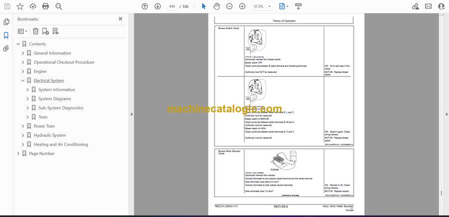
File Pages: 536

File Size: 13.48 MB (Speed Download Link)

Brand: John Deere

Model: 643J and 843J Wheeled Feller Buncher

Book No: TM2216

Type of Document: Operation and Test Technical Manual

Excellent Rating (4.8) on Trustpilot · Trusted Worldwide
Categories: ,

$ 40

Share:

John Deere 643J and 843J Wheeled Feller Buncher Operation and Test Technical Manual (TM2216)

John Deere 643J and 843J Wheeled Feller Buncher Operation and Test Technical Manual (TM2216)

John Deere 643J and 843J Wheeled Feller Buncher Index:

  • Contents
    • General Information
      • Safety Information
        • Recognize Safety Information
        • Understand Signal Words
        • Handle Fluids Safely—Avoid Fires
        • Prevent Battery Explosions
        • Prepare for Emergencies
        • Prevent Acid Burns
        • Handle Chemical Products Safely
        • Avoid High-Pressure Fluids
        • Park Machine Safely
        • Support Machine Properly
        • Wear Protective Clothing
        • Work in Clean Area
        • Service Machines Safely
        • Beware of Exhaust Fumes
        • Illuminate Work Area Safely
        • Replace Safety Signs
        • Use Proper Lifting Equipment
        • Remove Paint Before Welding or Heating
        • Avoid Heating Near Pressurized Fluid Lines
        • Service Tires Safely
        • Avoid Harmful Asbestos Dust
        • Practice Safe Maintenance
        • Use Proper Tools
        • Dispose of Waste Properly
        • Use Handholds and Steps
        • Travel Safely
        • Service Cooling System Safely
        • Handle Starting Fluid Safely
        • Prevent Machine Runaway
        • Handle Engine Side Panels Safely
      • Torque Values
        • Unified Inch Bolt and Cap Screw Torque Values
        • Metric Bolt and Cap Screw Torque Values
        • Check Oil Lines and Fittings
        • Service Recommendations for O-Ring Boss Fittings
        • Service Recommendations for Flat Face O-Ring Seal Fittings
        • Service Recommendations for 37° Flare and 30° Cone Seat Connectors
        • Service Recommendations For Flared Connections—Straight or Tapered Threads
        • Service Recommendations for Inch Series Four Bolt Flange Fittings
        • Service Recommendations for Metric Series Four Bolt Flange Fitting
    • Operational Checkout Procedure
      • Operational Checkout Procedure
        • Complete Machine Operational Checkout
          • Gauge and Indicator Checks
          • Brake System Checks
          • Steering System Checks
          • Driving Checks
          • Hydraulic System Checks
          • Cooling System Checks
          • Accessory Checks
          • Cab Components Checks
    • Engine
      • Theory of Operation
        • PowerTechPowerTech is a trademark of Deere & Company.®6.8 L John Deere Engine—Use CTM104, CTM220
        • Alternators and Starting Motors—Use CTM77
        • John Deere Engine Accessories—Use CTM67
        • General Engine Description
        • Engine—Sectional View
      • Electronic Fuel System Operation
        • About This Group
        • Fuel System Operation
        • Primary Fuel Filter Operation
        • Fuel Transfer Pump Operation
        • Final Fuel Filter Operation
        • High Pressure Fuel Pump Operation
        • High Pressure Common Rail (HPCR) Operation
        • Electronic Injector (EI) Operation
      • Electronic Control System Operation
        • About This Group
        • Electronic Control System Terminology
        • Electronic Control System Operation
        • Electronic Control System Overview
        • Monitoring Engine Parameters
        • Measuring Temperature
        • Measuring Pressure
        • Measuring Throttle Position
        • Measuring Engine Speed
        • Electronic Injector (EI) Wiring Harness Connector
        • Engine Control Unit (ECU)
        • Glow Plug Operation
        • Engine Protection
        • Derate Programs
        • Engine Control Unit (ECU) Self-Diagnosis
      • Observable Diagnostics and Tests
        • About This Group
        • JT05801 Clamp-On Electronic Tachometer Installation
        • E1 – Engine Cranks/Won’t Start
          • E1 – Engine Cranks/Won’t Start Diagnostic Procedure
        • E2 – Engine Misfires/Runs Irregularly
          • E2 – Engine Misfires/Runs Irregularly Diagnostic Procedure
        • E3 – Engine Does Not Develop Full Power
          • E3 – Engine Does Not Develop Full Power Diagnostic Procedure
        • E4 – Engine Emits Excessive White Exhaust Smoke
          • E4 – Engine Emits Excessive White Exhaust Smoke Diagnostic Procedure
        • E5 – Engine Emits Excessive Black Or Gray Exhaust Smoke
          • E5 – Engine Emits Excessive Black Or Gray Exhaust Smoke Diagnostic Procedure
        • E6 – Engine Will Not Crank
        • E7 – Engine Idles Poorly
        • E8 – Abnormal Engine Noise
        • E9 – Analog Throttle (A) Does Not Respond
        • E10 – Analog Throttle (B) Does Not Respond
        • F1 – Fuel Supply System Check
          • F1 – Fuel Supply System Check Diagnostic Procedure
        • F2 – Excessive Fuel Consumption
        • F3 – Fuel in Oil
        • D1 – ECU Does Not Communicate with DST or SERVICE ADVISOR
        • D1 – ECU Does Not Communicate with DST or SERVICE ADVISORSERVICE ADVISOR is a trademark of Deere & Company™
          • D1 – ECU Does Not Communicate With DST or SERVICE ADVISORSERVICE ADVISOR is a trademark of Deere & Company™ Diagnostic Procedure
        • D2 – Diagnostic Gauge Does Not Communicate With ECU
        • D2 – Diagnostic Gauge Does Not Communicate With ECU
          • D2 – Diagnostic Gauge Does Not Communicate With ECU Diagnostic Procedure
        • Check Fuel Supply Quality
        • Test for Air in Fuel
        • Check Fuel Supply Pressure
        • Check for Restricted Fuel Return Line
        • Bleed the Fuel System
        • Restarting Engine That Has Run Out Of Fuel
        • Check and Adjust High Pressure Fuel Pump Static Timing
        • Air Filter Restriction Indicator Switch Test
        • Engine Power Test Using Turbocharger Boost Pressure
        • Air Intake System Leakage Test
        • Radiator Air Flow Test
        • Glow Plug Check
    • Electrical System
      • System Information
        • Visually Inspect Electrical System
        • Electrical Circuit Malfunctions
        • High Resistance Circuit
        • Open Circuit
        • Grounded Circuit
        • Shorted Circuit
        • Multimeter
        • Seven Step Electrical Test Procedure
        • Schematic, Wiring Diagram, and Component Location Information
        • Reading a System Functional Schematic
        • Reading a Wiring Diagram
        • Reading a Connector End View Diagram
        • Electrical Schematic Symbols
      • System Diagrams
        • Component Identification Table
        • Electrical System Schematics
        • Battery Specifications
        • Battery Operation
        • Fuse (Blade-Type) Color Codes
        • Replacing Relays and Fuses
        • Fuse and Relay Panel
        • Fuse/Relay Wiring Harness
        • Ground Speed Limiter Wiring Harness
        • Saw Stop Solenoid Wiring Harness
        • Cab Harness Wiring Harness
        • Air Conditioner Wiring Harness
        • Engine Harness
        • Frame Harness
        • Electrical Components Alphabetical Index
      • Sub-System Diagnostics
        • Power Circuit Operational Information
        • Power Circuit Theory of Operation
        • Power Circuit Schematic
          • Power Circuit Diagnostic Procedures
        • Starting and Charging Circuit Operational Information
        • Starting and Charging Circuit Theory of Operation
        • Alternator Operation—95-Amp Bosch
        • Starting and Charging Circuit Schematic
          • Starting and Charging Circuit Diagnostic Procedures
        • ECU and Engine Circuits Operational Information
        • ECU and Engine Circuits Theory of Operation
        • Engine Control Unit (ECU) Circuits Schematics
          • Display Monitor Circuit Diagnostic Procedures
        • Park Brake Circuit Specifications
        • Park Brake Circuit Operational Information
        • Park Brake Circuit Theory of Operation
        • Park Brake Circuit Schematic
          • Park Brake Circuit Diagnostic Procedures
        • Two-Speed Gearbox Theory of Operation
        • Two-Speed Gearbox Circuit Schematic
          • Gear Speed Circuit Diagnostic Procedures
        • Display Monitor Indicator Light and Gauges Circuit Specifications
        • Display Monitor Indicator Light and Gauges Circuit Theory of Operation
        • Display Monitor Indicator Light and Gauges Circuit Schematic
          • Display Monitor and Gauges Circuit Diagnostic Procedures
        • Accumulator Arm (Shear) Circuit Operational Information
        • Accumulator Arm (Shear) Circuit Theory of Operation
        • Controls Circuits Specifications
        • Controls Circuits Operational Information
        • Controls Circuits Theory of Operation
        • Controls Circuits Schematics
        • Controls Circuits Diagnostic Information
          • Controls Circuits Diagnostic Procedures
        • Accessory Circuit Operational Information
        • Accessory Circuit Theory of Operation
        • Accessory Circuit Schematic
          • Accessory Circuit Diagnostic Procedures
        • Light Circuit Operational Information
        • Lights Circuits Theory of Operation
        • Light Circuit Schematic
          • Light Circuit Diagnostic Procedures
        • Air Conditioning Circuit Operational Information
        • Air Conditioning Circuit Theory of Operation
        • Air Conditioning Circuits Schematics
          • Air Conditioning Circuit Diagnostic Procedures
        • Blower Circuit Operational Information
        • Blower Circuit Theory of Operation
        • Reversing Fan Circuit Specifications
        • Reversing Fan Circuit Theory of Operation
        • Reversing Fan Circuit Schematics
          • Reversing Fan Diagnostic Procedures
        • Diagnose Battery Malfunctions
      • Tests
        • Procedure for Testing Batteries
        • Using Booster Batteries—12 Volt System
    • Power Train
      • Theory of Operation
        • Power Train Operation
        • Pump Drive Gearbox Operation
        • Hydrostatic Transmission Operation
        • Hydrostatic Transmission Oil Filter Operation
        • Hydrostatic Pump Operation
        • Hydrostatic Pump Swashplate Operation
        • Multi-Function Valve, Charge Pressure Relief Valve, and Displacement Control Valve Operation
        • Hydrostatic Pump Control Operation—Neutral
        • Hydrostatic Pump Control Operation—Forward
        • Hydrostatic Pump Control Operation—Reverse
        • Hydrostatic Pump Displacement Control Valve Operation—Feedback Linkage
        • Hydrostatic Motor Operation
        • Hydrostatic Motor Operation—Neutral
        • Hydrostatic Motor Operation—Decreasing Displacement (Acceleration)
        • Hydrostatic Motor Pressure Override (POR) Valve Operation
        • Hydrostatic Motor Rate-of-Shift Orifice Operation
        • Hydrostatic Transmission Flushing System Operation
        • Loop Flushing Valve and Motor Charge Relief Valve Operation
        • Hydrostatic Transmission Control Circuit Operation
        • Forward-Neutral-Reverse (FNR) Control Valve Operation
        • Two-Speed Gearbox Operation
        • Service Brake Circuit Operation—Continuous Saw/Shear Machine
        • Brake Accumulator Operation
        • Brake Valve Operation
        • Differential and Differential Lock Operation
        • Differential Lock Solenoid Valve Operation
        • Differential Lock Pump
        • Differential Lock Filter
        • TEAMMATE II Axle Operation
        • Final Drive Operation
        • Axle Outer Seal and Bearing Operation
      • Diagnostic Information
        • Diagnose Hydrostatic Transmission Malfunctions
        • Diagnose Differential Malfunctions
        • Hydrostatic Transmission Schematic—Neutral
        • Hydrostatic Transmission Component Location
        • Service Brake and Park Brake Component Location—Continuous Saw/Shear Machine
        • Differential Lock and Axle Component Location—Continuous Saw/Shear Machine
      • Adjustments
        • JT02156A Digital Pressure/Temperature Analyzer Installation
        • JT05800 Digital Thermometer Installation
        • JT05801 Clamp-On Electronic Tachometer Installation
        • JT07148 Digital Hydraulic Tester
        • Hydraulic Oil Warm-Up Procedure
        • Hydrostatic Transmission Start-Up Procedure
        • Hydrostatic Motor Minimum Displacement Adjustment
        • FNR Control Valve Pedal Adjustment
        • Service Brake Bleed Procedure
        • Service Brake Operation Check
        • Differential Lock Start-Up Procedure
        • Ground Speed Limiter Adjustment
      • Tests
        • Hydrostatic (HST) Neutral Charge Relief Valve Pressure Test And Adjustment
        • Hydrostatic (HST) System Charge Pressure Adjustment and Flow Test
        • Hydrostatic (HST) Pump Pressure Setting and Adjustment
        • Hydrostatic (HST) Motor Begin Regulation Pressure Test and Adjustment
        • Hydrostatic (HST) Motor Pressure Override (POR) Test and Adjustment
        • Hydrostatic (HST) Motor Minimum Displacement Screw Tamper Proof Cap
        • Hydrostatic (HST) Motor Charge Relief Valve Test
        • Hydrostatic (HST) Motor Leakage Test
        • Brake Valve Pressure Test
        • Brake and Pilot Accumulator Precharge Test
        • Differential Lock Pressure Test
        • Ground Speed Limiter Test
        • Axle Boost Pressure Setting
    • Hydraulic System
      • Theory of Operation
        • Main Hydraulic Pump Operation—Continuous Saw/Shear Machine
        • Main Hydraulic Pump Control Operation—Continuous Saw Machine
        • Hydraulic Tank
        • Filler Pump
        • Power Management Valve Operation
        • Saw Pump Operation—Continuous Saw/Shear Machine
        • Continuous Saw Pump Control Valve Operation
        • Continuous Saw On-Off Control Valve Circuit Operation
        • Shear Valve Circuit Operation
        • Brake and Pilot Pump Operation—Shear Machine
        • Brake and Pilot Pump Pressure Compensator Standby Operation—Shear Machine
        • Brake and Pilot Pump Pressure Compensator Going into Stroke Operation—Shear Machine
        • Steering Circuit Operation (Continuous Saw Wheel Steer Machine)
        • Steering Circuit Operation (Continuous Saw Lever Steer Machine)
        • Steering Valve Relief and Anti-Cavitation Check Valve Operation (Continuous Saw Wheel Steer Machine)
        • Main Control Valve Operation—Continuous Saw Machine
        • Load Sense Circuit Operation—Neutral (Continuous Saw Machine)
        • Load Sense Circuit Operation—Steering (Continuous Saw Machine)
        • Load Sense Circuit Operation—Steering and Boom Down (Continuous Saw Machine)
        • Load Sense Circuit Operation—Tilt Back and Accumulator Open (Continuous Saw Machine)
        • Load Sense Relief Valve Operation—Continuous Saw Machine
        • System Relief Valve Operation
        • Circuit Relief Valve Operation
        • Main Control Valve Operation (Shear Machine)
        • Main Control Valve Section Operation—Shear Machine
        • Mid-Inlet Valve (Flow Combiner) Section Operation—Shear Machine
        • Steering Cylinder Operation
        • Cab Tilt Cylinder Operation
        • Boom Lift Cylinder Operation
        • Boom Tilt Cylinder Operation
        • Boom Cylinder Operation
        • Lever Steer Controller Operation
        • Shear Grapple Foot Controller Operation
        • Pilot Controller Operation
        • Return Filter Operation
        • Pilot Pressure Source Manifold
        • Pilot Circuit Operation
        • Pilot Accumulator Operation
        • Park Brake and Differential Lock Solenoid Valve Operation
        • Accumulator Open/Close Solenoid Valve Operation
        • Cooling Fan Hydraulic System Circuits
        • Cooling Fan Pump
        • Cooling Fan Motor
        • Cooling Fan Reverse Valve
      • Diagnostic Information
        • Diagnose Hydraulic System Malfunctions
        • Diagnose Steering Circuit Malfunctions
        • Diagnose Shear Lift, Shear Tilt, and Accumulator Circuit Malfunctions
        • Diagnose Head Grapple Arm Circuit Malfunctions
        • Diagnose Pilot Circuit Malfunctions
        • Standard Hydraulic Schematic Symbols
        • Steering Circuit Component Location
        • Hydraulic Pilot System Component Location
        • Main Hydraulic Schematic—Continuous Saw Machine
        • Main Hydraulic Schematic—Shear Machine
      • Adjustments
        • Main Hydraulic Pump Standby Pressure Adjustment—Continuous Saw Machines
        • Main Hydraulic System Load Sense (LS) Relief and Main Pump Cut-Off Pressure Adjustment—Continuous Saw Machine
        • Hydraulic Main Pump Cut-off Pressure Adjustment
        • Pilot Source Manifold Standby Pressure Adjustment
        • Continuous Saw Pump Standby Pressure Adjustment
        • Shear Pump Maximum Pressure Adjustment
        • Continuous Saw Pump Maximum Pressure Adjustment
        • Continuous Saw Motor Begin of Regulation (BOR) Adjustment
        • Power Management Valve Adjustment
        • Shear Grapple Pilot Controller Pedal Adjustment
        • Hydraulic Oil Clean-Up Procedure Using Portable Filter Caddy
      • Tests
        • Main Control Valve Port Relief Valve Test and Adjustment—Continuous Saw Machines
        • Main Control Valve Load Sense Relief Valve Test and Adjustment—Continuous Saw Machines
        • Main Control Valve System Relief Valve Test and Adjustment—Saw and Shear Machines
        • Main Control Valve Port Relief Valve Test and Adjustment—Shear Machines
        • Cooling Fan Pump Pressure Setting
        • Continuous Saw Pump Flow Test
        • Continuous Saw Pump Case Drain Flow Test
        • Main Hydraulic Pump Flow Test—Continuous Saw Machines
        • Shear Pump Flow Test—Shear Machines
        • Steering Valve Internal Leakage Test—Wheel Steer Machines
        • Hydraulic Cab Tilt Procedure
        • Bleeding Cab Tilt Cylinder and Pump
        • Cylinder Leakage Test
        • Cycle Times Test
    • Heating and Air Conditioning
      • Theory of Operation
        • Proper Refrigerant Handling
        • R134a Refrigerant Cautions
        • Refrigerant Theory of Operation
        • Air Conditioning Circuit Operational Information
        • Air Conditioning Circuit Theory of Operation
        • Blower Circuit Operational Information
        • Blower Circuit Theory of Operation
        • Air Conditioning Circuit Schematic
          • System Operating Checks
        • Receiver/Dryer Operation
        • Expansion Valve Operation
        • Compressor Relief Valve Operation
        • Temperature Control
      • System Operational Checks
        • Air Conditioning Operational Checks
          • Visual Inspection of Components
          • System Operating Checks
      • Diagnostic Information
        • Diagnose Air Conditioning Electrical Malfunctions
        • Air Conditioning Component Location Diagram
      • Adjustments
        • Proper Refrigerant Handling
        • R134a Refrigerant Cautions
        • R134a Component Oil Charge
        • R134a Refrigerant Recovery, Recycling and Charging Station Installation Procedure
        • Recover R134a System
        • Evacuate R134a System
        • Charge R134a System
        • Check Serpentine Belt Tensioner
      • Tests
        • Proper Refrigerant Handling
        • R134a Refrigerant Cautions
        • R134a Air Conditioning System Test
        • Pressure Diagnostic Chart
        • Air Conditioner High/Low Pressure Switch Test
        • Freeze Control Switch
        • Leak Testing
        • Refrigerant Hoses and Tubing Inspection
  • Page Number
    • Section 9000
      • Group 01
      • Group 03
    • Section 9005
      • Group 10
    • Section 9010
      • Group 05
      • Group 130
      • Group 140
      • Group 150
    • Section 9015
      • Group 05
      • Group 10
      • Group 15
      • Group 25
    • Section 9020
      • Group 05
      • Group 15
      • Group 20
      • Group 25
    • Section 9025
      • Group 05
      • Group 15
      • Group 20
      • Group 25
    • Section 9031
      • Group 05
      • Group 10
      • Group 15
      • Group 20
      • Group 25

John Deere

Latest Product

0
    0
    Your Cart
    Your cart is emptyReturn to Shop